Module13.2 4In8Out


描述
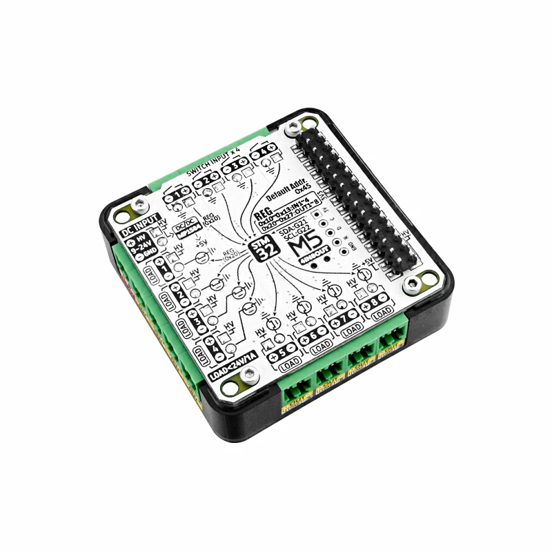
Module13.2 4In8Out 是一款8 路 MOS 驱动输出 + 4 路无源接点输入的 IO 扩展模块。它采用 STM32F030 作为 I2C 的 IO 扩展芯片,支持 9 ~ 24V 电源输入,内置转 5V DC-DC 电路。
产品特性
- 适用于 Basic/Fire/Core2/CoreS3 等主机
- 采用 STM32F030 作为 IO 扩展芯片, 采用 I2C 与主机通信, I2C 地址能通过写入寄存器修改
- 8路共电源正极 MOS 管驱动电路(A3400), 能直接驱动负载, 每路最大通断电流 1A
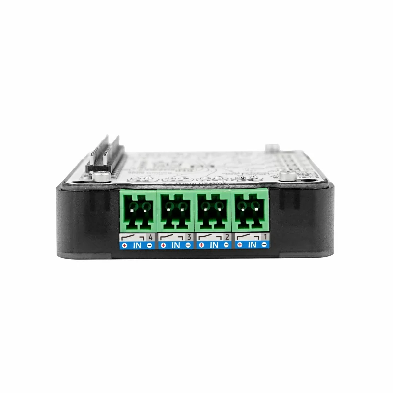
- 4路共地无源接点输入, 不能接入有源信号 或 大于5V的信号
- 内置 MP1584 9~24V -> 5V DC-DC电路
包装内容
- 1 x Module13.2 4In8Out
- 13 x 2P 端子
应用场景
- 多通道负载驱动(继电器、气阀、单向电机、信号指示灯等)
- 限位开关、按键检测
规格参数
| 规格 | 参数 |
|---|---|
| MCU | STM32F030F4P6 |
| 供电电压 | 9~24V |
| 输出通道 | 8 |
| 输入通道 | 4 |
| 输出电流 | 每路 1A, 总电流不大于8A |
| 通讯接口 | I2C |
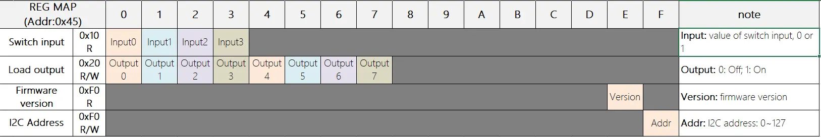
| I2C地址 | 默认0x45, 可通过写入寄存器0xF0修改 |
| 产品重量 | 21.9g |
| 毛重 | 52.5g |
| 产品尺寸 | 54 x 54 x 13mm |
| 包装尺寸 | 95 x 65 x 25mm |
操作说明
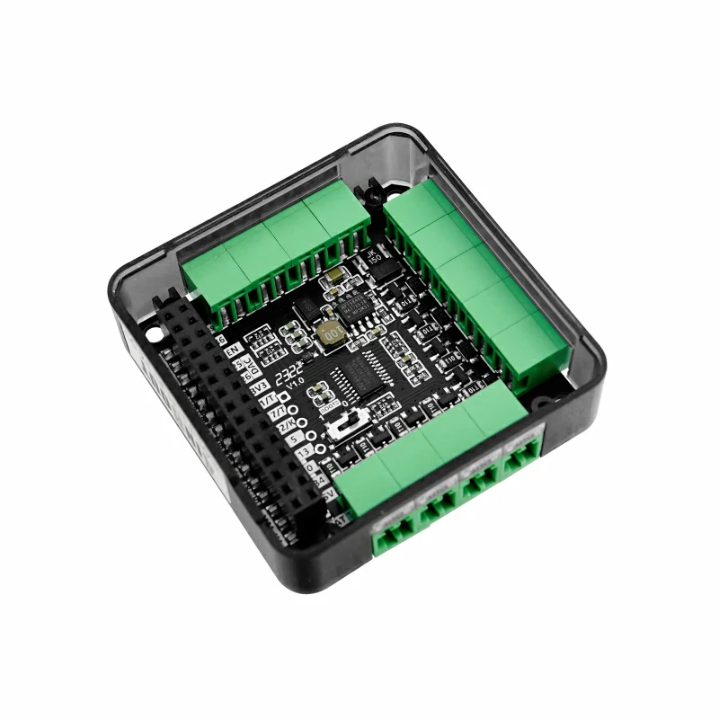
板载拨动开关的作用
下图红色框内是boot0的控制拨动开关,拨到1端拉高是刷写固件模式。拨到0端拉低是从闪存开始读取用户程序,即正常使用模式
.png)
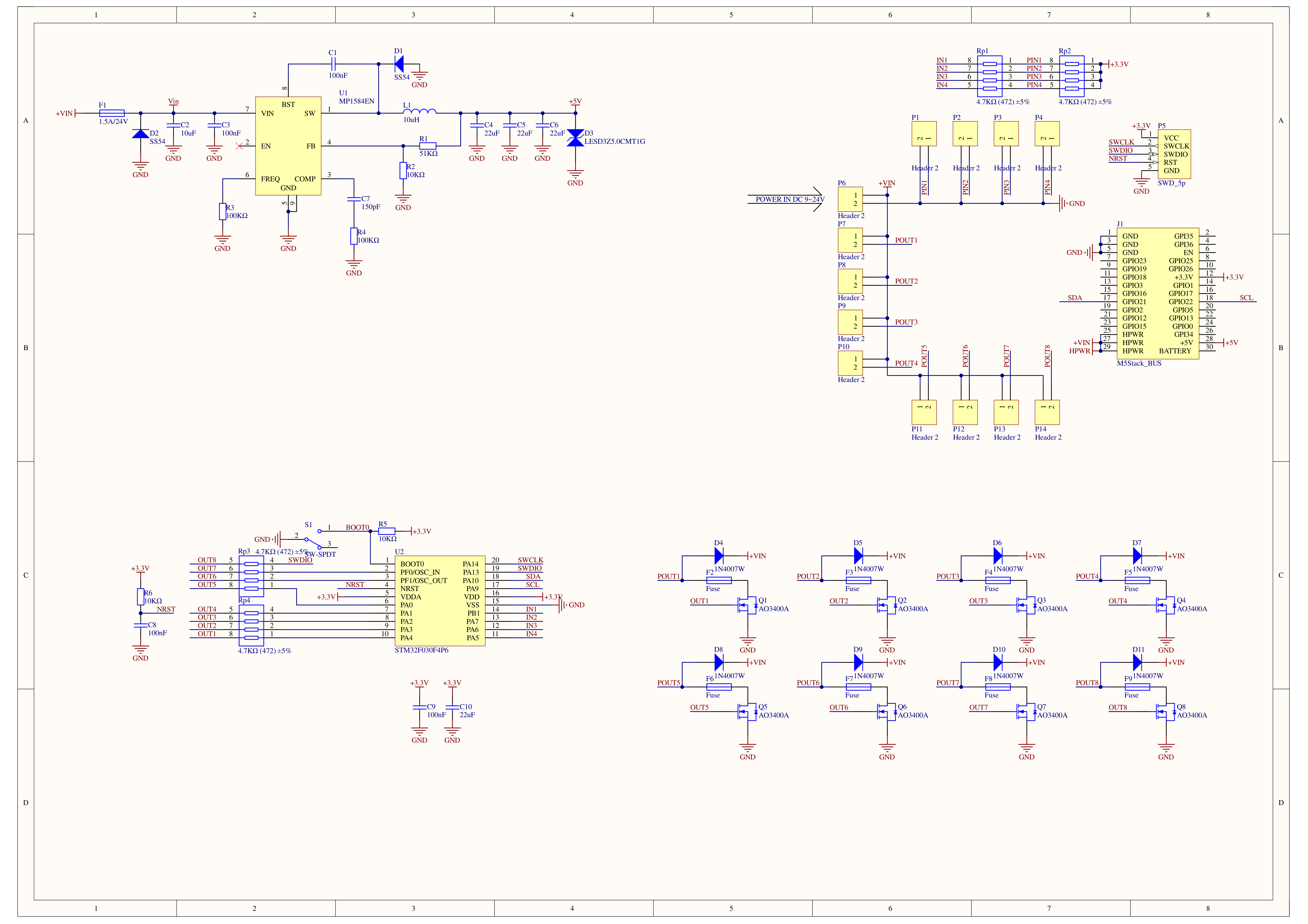
原理图
1/1
管脚映射
| M5Core | GPIO22 | GPIO21 | 5V | GND |
|---|---|---|---|---|
| 4IN8OUT MODULE 13.2 | SCL | SDA | 5V | GND |
软件开发
Arduino
#include <M5Stack.h>
#include "MODULE_4IN8OUT.h"

MODULE_4IN8OUT module;

int _I2C_dev_scan();

void setup() {
    M5.begin(1,1,1,1);  // Init M5Stack.  初始化M5Stack

    // while (1) {
    //     _I2C_dev_scan();
    //     delay(1000);
    // }


    while (!module.begin(&Wire, 21, 22, MODULE_4IN8OUT_ADDR)) {
        Serial.println("4IN8OUT INIT ERROR");
        M5.Lcd.println("4IN8OUT INIT ERROR");
        _I2C_dev_scan();
        delay(1000);
    };
    Serial.println("4IN8OUT INIT SUCCESS");
}

// void loop() {

// }

long interval = 0;
bool level    = false;

void loop() {
    for (uint8_t i = 0; i < 4; i++) {
        if (module.getInput(i) != 1) {
            // M5.Lcd.fillRect(60 + 60 * i, 0, 25, 25, TFT_BLACK);
            M5.Lcd.fillRect(60 + 60 * i, 0, 25, 25, TFT_GREEN);
        } else {
            // M5.Lcd.fillRect(60 + 60 * i, 0, 25, 25, TFT_BLACK);
            // M5.Lcd.drawRect(60 + 60 * i, 0, 25, 25, TFT_GREEN);
            M5.Lcd.fillRect(60 + 60 * i, 0, 25, 25, TFT_RED);
        }
        M5.Lcd.drawString("IN" + String(i), 40 + 60 * i, 5);
    }
    M5.Lcd.drawString("4IN8OUT MODULE", 60, 80, 4);
    // M5.Lcd.drawString("FW VERSION:" + String(module.getVersion()), 70, 120, 4);
    if (millis() - interval > 1000) {
        interval = millis();
        level    = !level;
        for (uint8_t i = 0; i < 8; i++) {
            module.setOutput(i, level);
            if (level) {
                M5.Lcd.fillRect(20 + 35 * i, 200, 25, 25, TFT_BLACK);
                M5.Lcd.fillRect(20 + 35 * i, 200, 25, 25, TFT_BLUE);
            } else {
                M5.Lcd.fillRect(20 + 35 * i, 200, 25, 25, TFT_BLACK);
                M5.Lcd.drawRect(20 + 35 * i, 200, 25, 25, TFT_BLUE);
            }
            M5.Lcd.drawString("OUT" + String(i), 18 + 35 * i, 180);
            // delay(50);
        }
    }
    // if (M5.BtnB.wasPressed()) {
    //     if (module.setDeviceAddr(0x66)) {
    //         Serial.println("Update Addr: 0x66");
    //     }
    // }
    // M5.update();

    delay(500);
}


int _I2C_dev_scan() {
    uint8_t error, address;
    int nDevices;

    Serial.println("[I2C_SCAN] device scanning...");

    nDevices = 0;
    for (address = 1; address < 127; address++ ) {
        // The i2c_scanner uses the return value of
        // the Write.endTransmisstion to see if
        // a device did acknowledge to the address.
        Wire.beginTransmission(address);
        error = Wire.endTransmission();

        if (error == 0) {
            Serial.print("[I2C_SCAN]: device found at address 0x");
            if (address < 16)
                Serial.print("0");
            Serial.print(address, HEX);
            Serial.println(" !");

            nDevices++;
        }
        else if (error == 4) {
            Serial.print("[I2C_SCAN]: unknow error at address 0x");
            if (address < 16)
                Serial.print("0");
            Serial.println(address, HEX);
        }
    }

    Serial.print("[I2C_SCAN]:");
    Serial.printf(" %d devices was foundrn", nDevices);
    return nDevices;
}UiFlow1
通信协议