


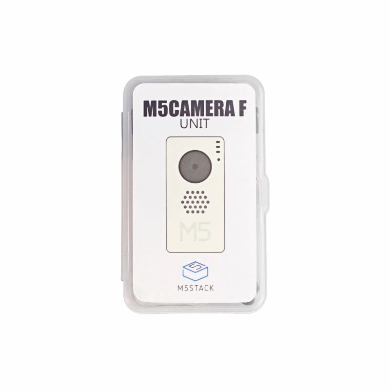
M5CameraF New
Description
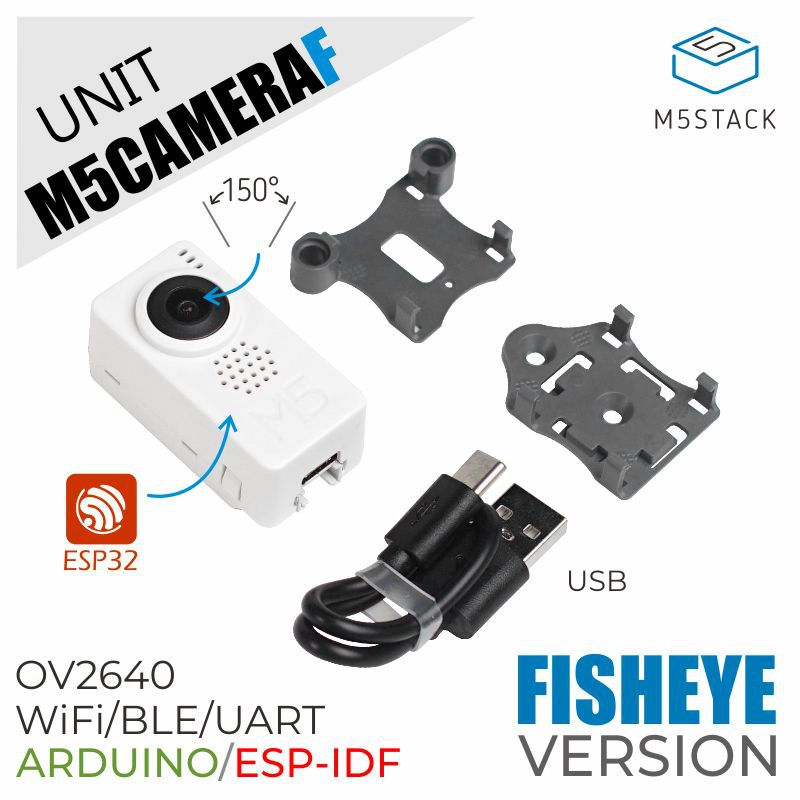
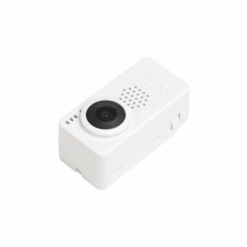
M5CameraF is a development board for image recognition. It features an ESP32(4M Flash + 520K RAM) chip and 2-Megapixel camera (OV2640).
The module offers plenty of storage with an extra 4 Mbyte PSRAM. It also supports image transmission via Wi-Fi and debugging through USB Type-C port.
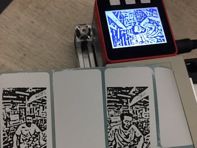
The hardware comes with preloaded software, programmed by ESP-IDF. It is an application to run Wi-Fi camera. The output image resolution is 600*800, since it's 2MP camera, you sure can optimize the software to output a better resolution image.
what this software can do?
- Power the board via USB type-C or GROVE
- Use your phone to Wi-Fi scan an AP name start with 'm5stack-' and click to connect this AP.
- Open up web browser on your phone and visit 192.168.4.1
- Then here comes the picture. Video is about 5-6 frames per seconds. not super fast.
Product Features
- CP2104 USB-to-TTL converter
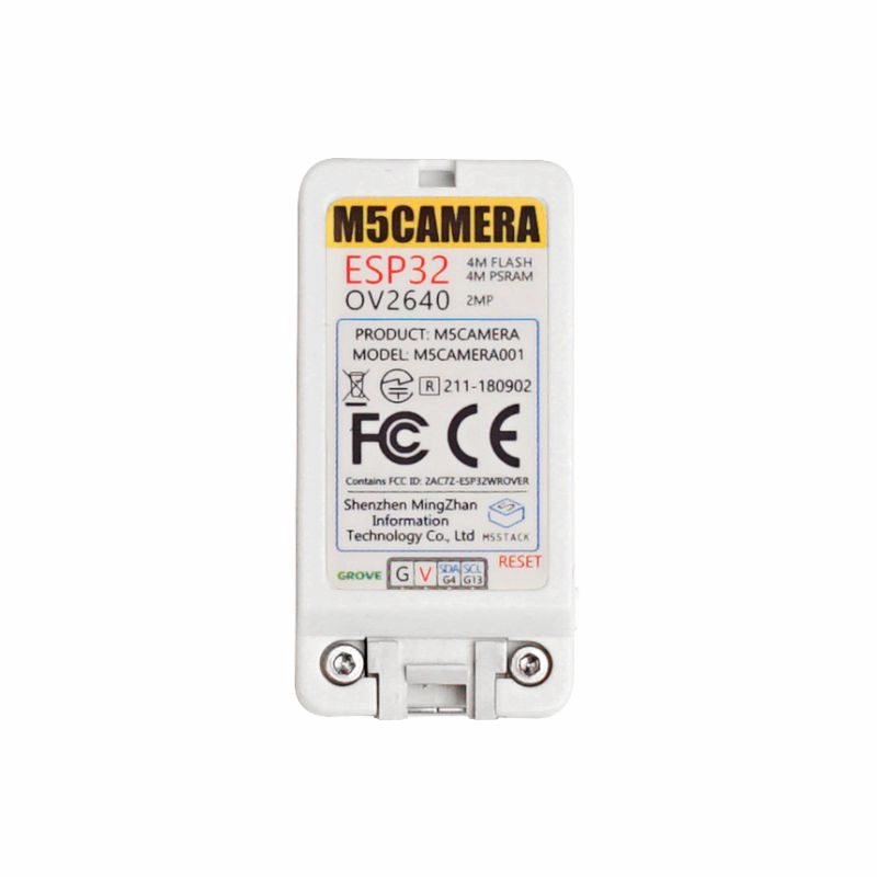
- ESP32-WROVER (PCB Antenna)
- WIFI image transmission
- OV2640 sensor
- Camera Field of View : 150 degree
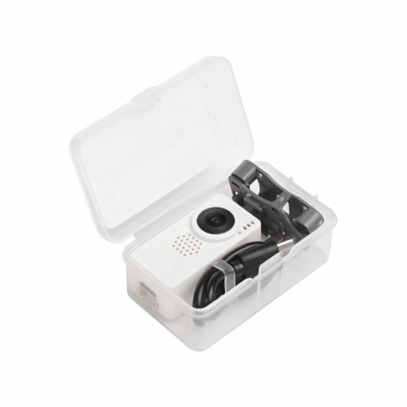
Include
- 1x M5CameraF
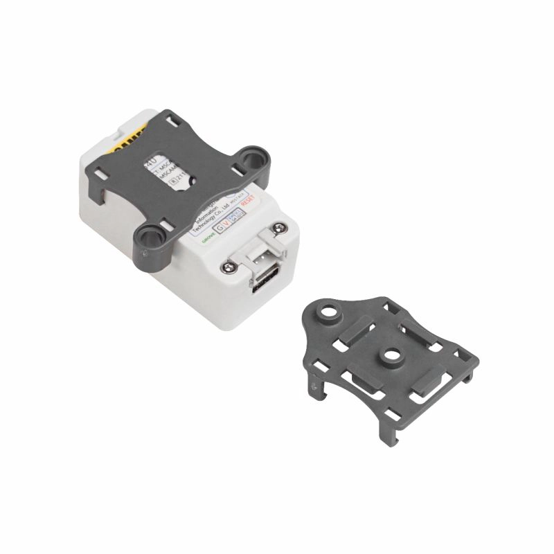
- 1x LEGO Adapter
- 1x Wall/1515
- 1x Type-C USB(20cm)
Specification
| Resources | Parameter |
|---|---|
| Flash | 4M |
| RAM | 4MB |
| Image Sensor | OV2640 |
| Maximum resolution | 2M pixel |
| Output format | YUV(422/420)/YCbCr422,RGB565/555,8-bit compressed data,8-/10-bit Raw RGB data |
| FOV | 150° |
| CCD Size | 1/4 inch |
| Net weight | 17g |
| Gross weight | 41g |
| Product Size | 24*48*19mm |
| Package Size | 75*45*30mm |
EasyLoader
1.EasyLoader is a simple and fast program burner. Every product page in EasyLoader provides a product-related case program. It can be burned to the master through simple steps, and a series of function verification can be performed. .
- After downloading the software, double-click to run the application, connect the M5 device to the computer through the data cable, select the port parameters, click "Burn" to start burning. (For M5StickC burning, please Set the baud rate to 750000 or 115200)
PinMap
Camera Interface PinMap
| Interface | Camera Pin | M5CameraF |
|---|---|---|
| SCCB Clock | SIOC | IO23 |
| SCCB Data | SIOD | IO22 |
| System Clock | XCLK | IO27 |
| Vertical Sync | VSYNC | IO25 |
| Horizontal Reference | HREF | IO26 |
| Pixel Clock | PCLK | IO21 |
| Pixel Data Bit 0 | D2 | IO32 |
| Pixel Data Bit 1 | D3 | IO35 |
| Pixel Data Bit 2 | D4 | IO34 |
| Pixel Data Bit 3 | D5 | IO5 |
| Pixel Data Bit 4 | D6 | IO39 |
| Pixel Data Bit 5 | D7 | IO18 |
| Pixel Data Bit 6 | D8 | IO36 |
| Pixel Data Bit 7 | D9 | IO19 |
| Camera Reset | RESET | IO15 |
| Camera Power Down | PWDN | see Note 1 |
| Power Supply 3.3V | 3V3 | 3V3 |
| Ground | GND | GND |
GROVE Interface
| Grove | M5CameraF |
|---|---|
| SCL | IO13 |
| SDA | IO4 |
| 5V | 5V |
| GND | GND |
LED Interface
| LED | M5CameraF |
|---|---|
| LED_Pin | IO14 |
NOTE:
- Camera Power Down pin does not need to be connected to ESP32 GPIO. Instead it may be pulled down to ground with 10 kOhm resistor.
View M5 camera series/product differences
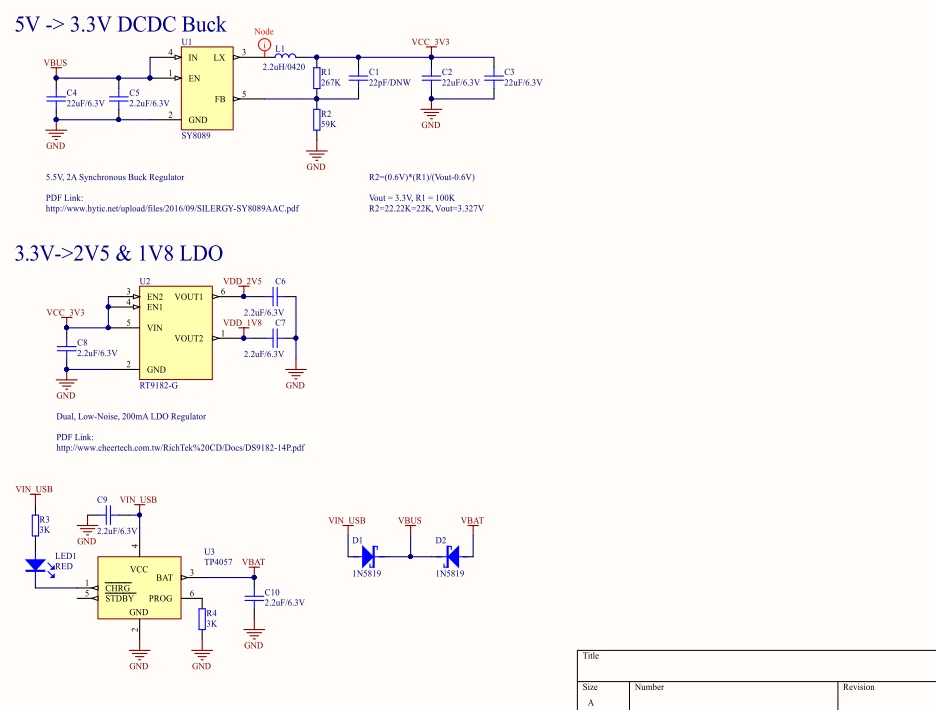
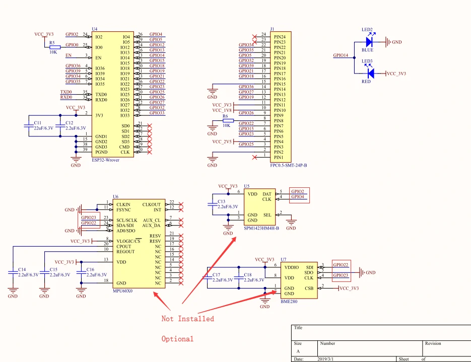
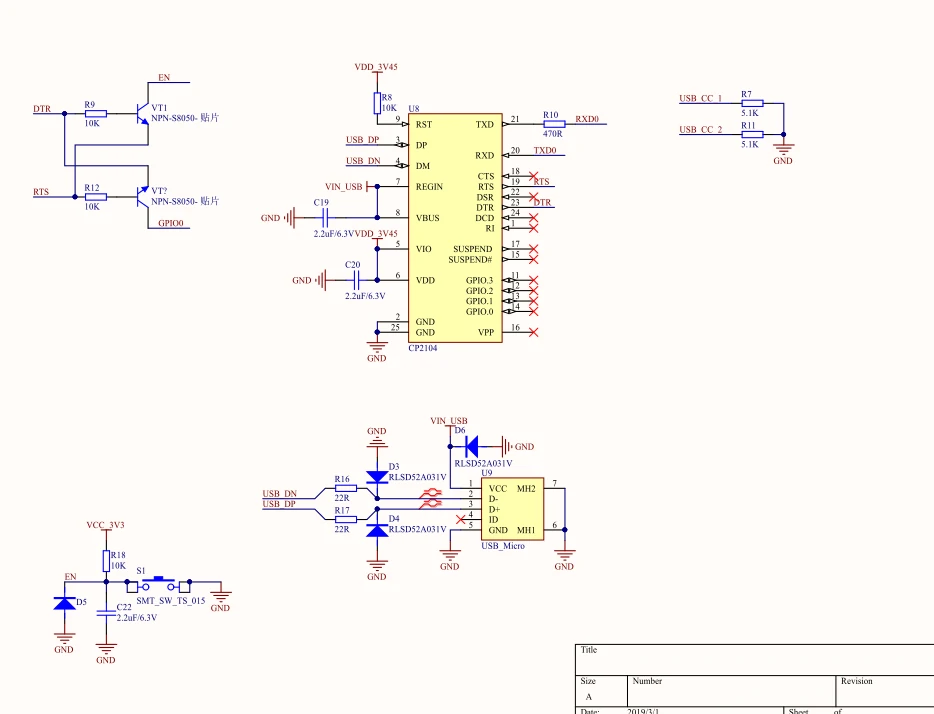
Schematic
Power circuit
Chip peripheral circuit
USB to serial port part of the circuit
Related Link
Learn
Example
Firmware
Arduino
Code
** Serial communication-M5Core **(The serial communication routine is the communication between the camera and the M5Core.)