
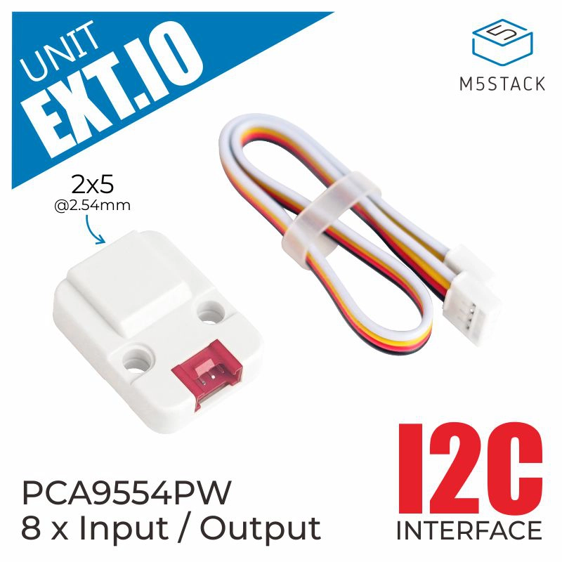
Unit EXT.IO
SKU:U011
Description
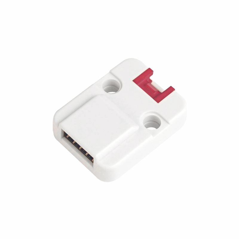
Unit EXT.IO is a parallel port expander. It integrates the IO expansion chip PCA9554PW, supporting expansion to 8 GPIOs, and can be used for 2.3 ~ 5.5V VCC, open drain, pull-up, and interrupt output operations. Through the I2C interface (serial clock SCL, serial data SDA), it assists most microcontrollers in providing I/O expansion. For developers who are short on I/O pins and do not want to waste resources by adding extra controllers, Unit EXT.IO is a good assistant.
Features
- I2C Communication
- Input/Output Expansion
- HY2.0-4P Interface, supports UIFlow and Arduino.
- 2 x LEGO Compatible Holes
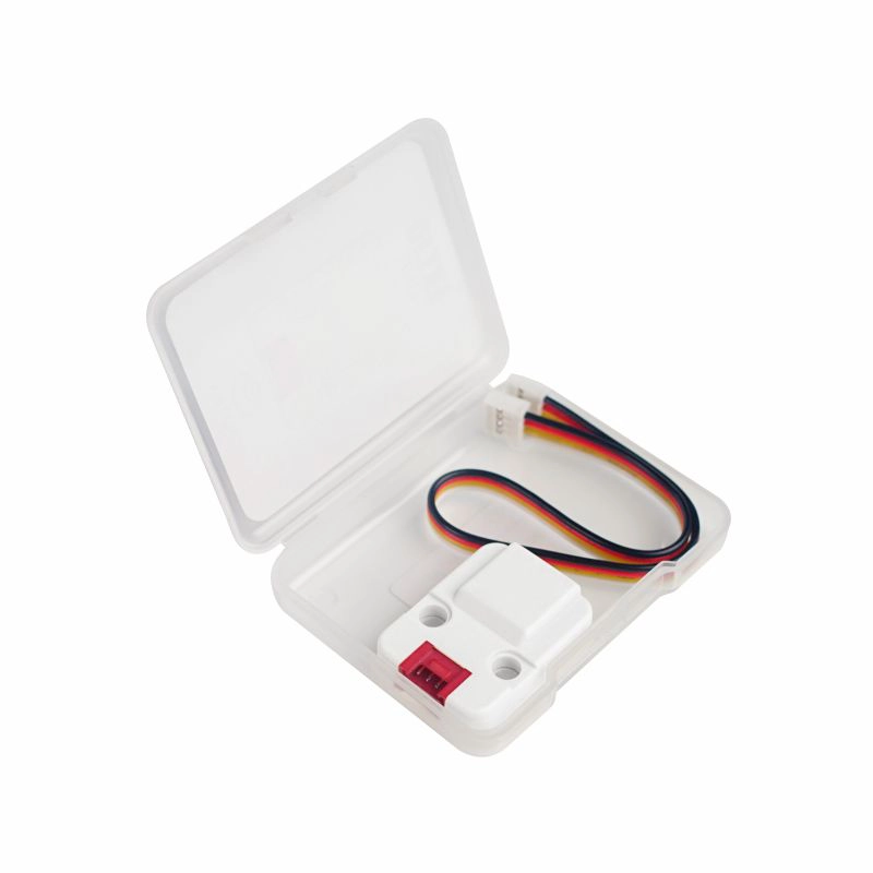
Includes
- 1 x Unit EXT.IO
- 1 x HY2.0-4P Grove Cable (20cm)
Specifications
| Specification | Parameter |
|---|---|
| Communication Interface | I2C @0x27 |
| I/O Expansion | 8 |
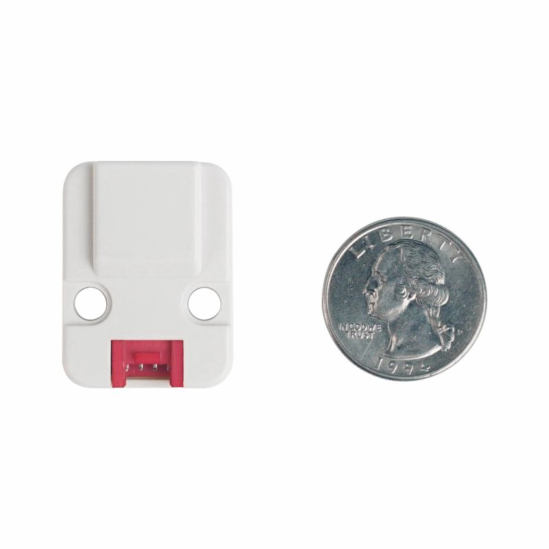
| Net Weight | 5g |
| Gross Weight | 16g |
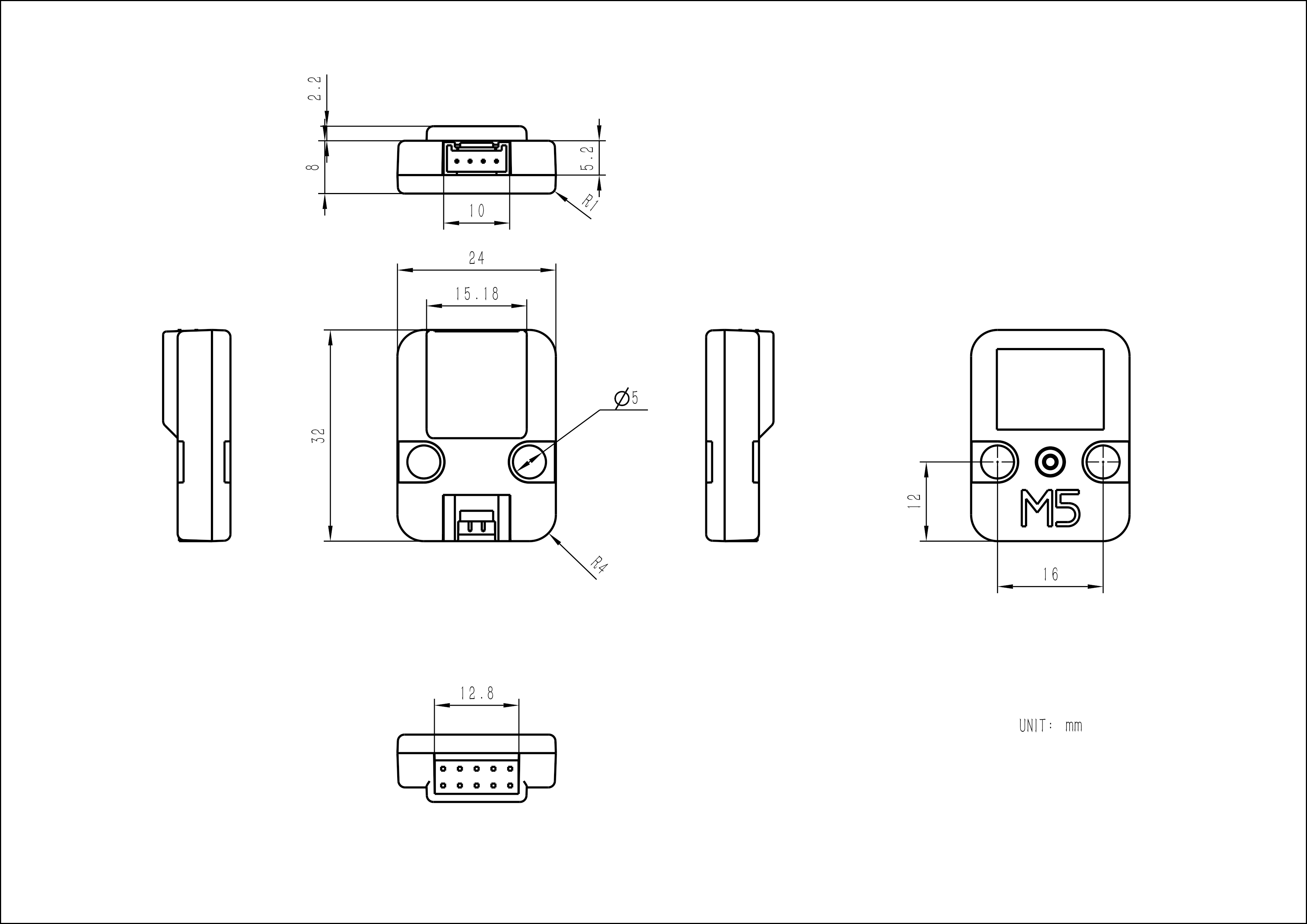
| Product Size | 32 x 24 x 11mm |
| Package Size | 67 x 53 x 12mm |
Learn
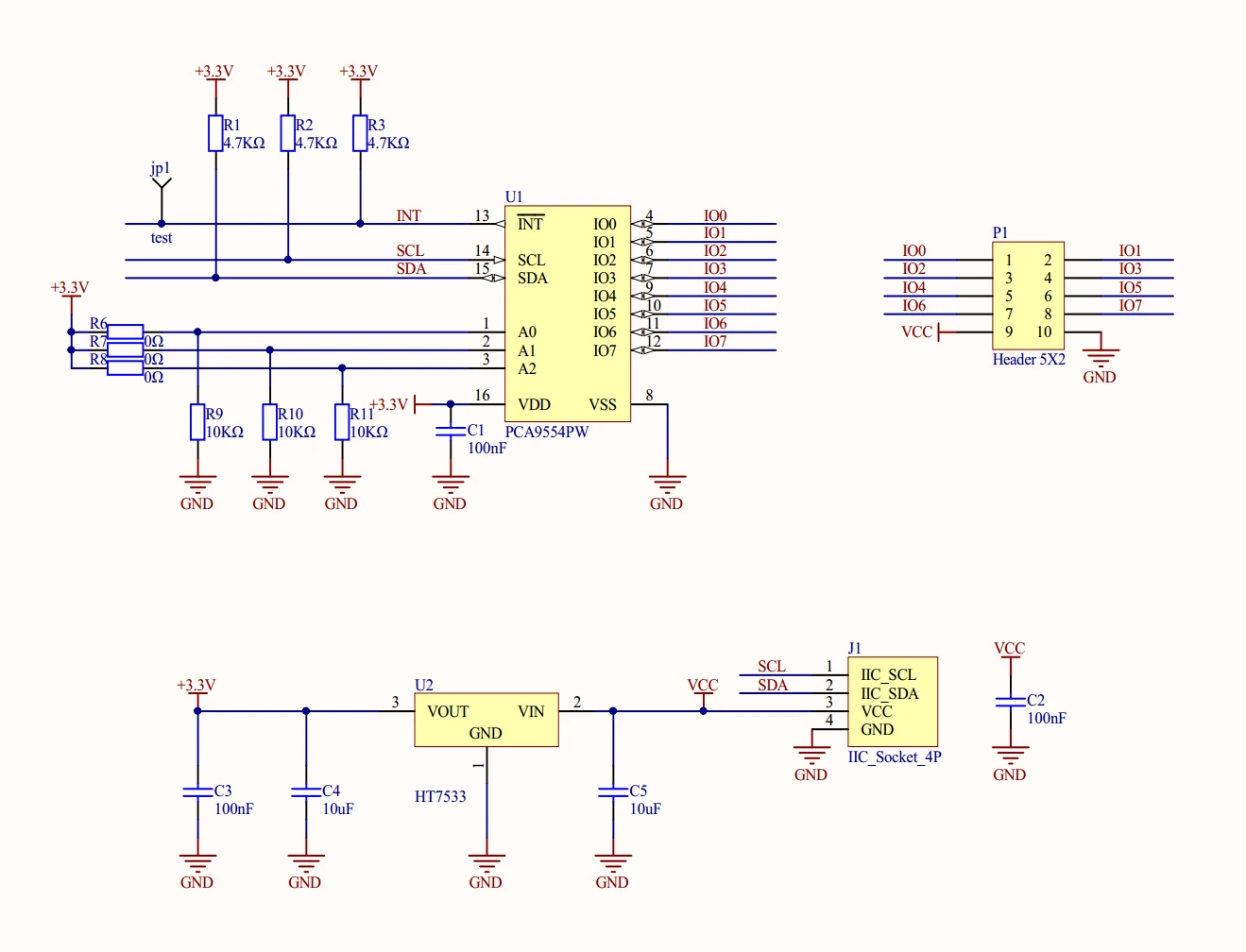
According to the schematic and PCA9554PW datasheet, this unit can modify the device's I2C address by controlling the level combination of A0~A2 pins. (The default address is 0x27, for more information please refer to the datasheet) Three soldering positions for chip resistors are reserved on the unit's PCB, namely A0-A2 (R6-R8), as shown in the figure below.
Schematics
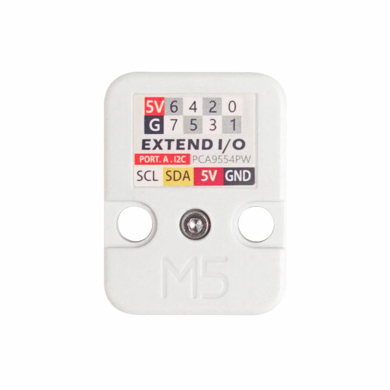
PinMap
Unit EXT.IO
| HY2.0-4P | Black | Red | Yellow | White |
|---|---|---|---|---|
| PORT.A | GND | 5V | SDA | SCL |
Model Size
Datasheets
Softwares
Arduino
UiFlow1
UiFlow2
EasyLoader
| Easyloader | Download Link | Note |
|---|---|---|
| Unit EXT.IO Easyloader | download | / |