M5GO IoT Kit v2.7
SKU:K006-V27
Description
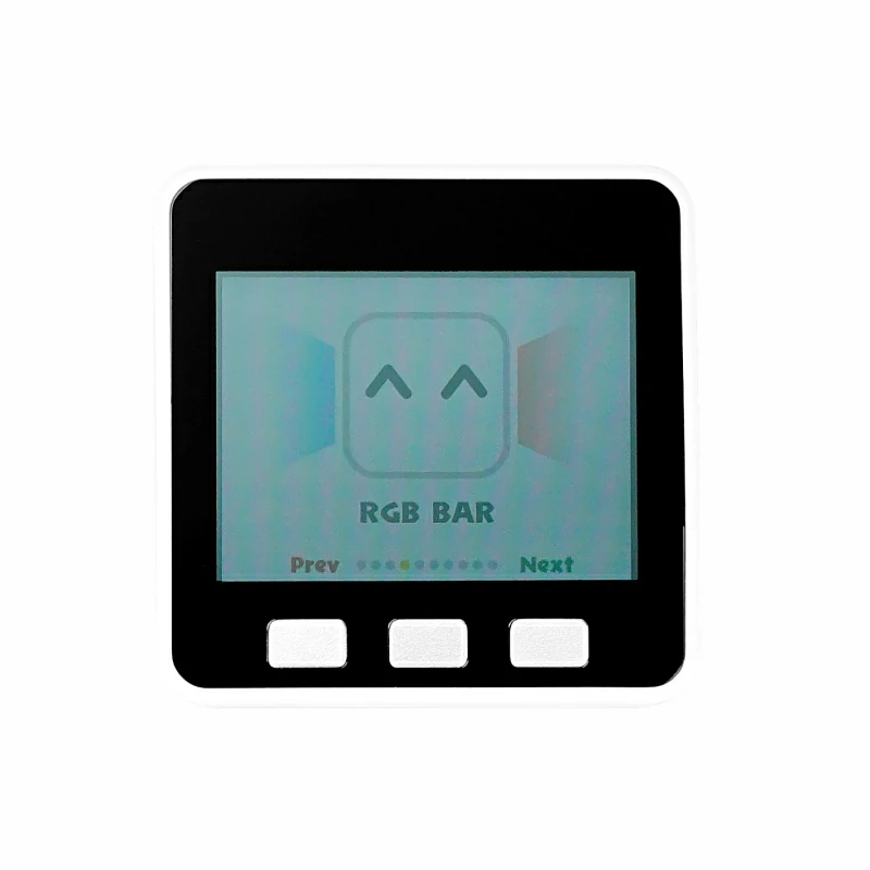
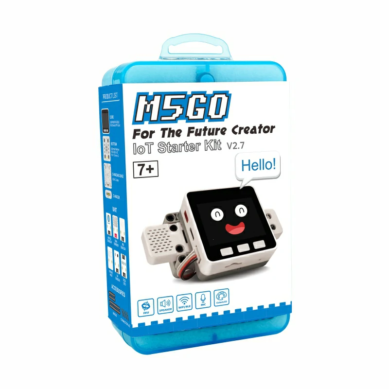
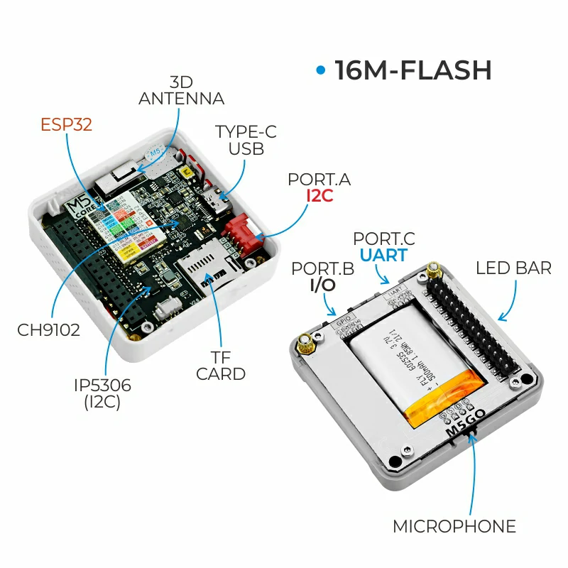
M5GO IoT Kit v2.7 is a high cost-performance entry-level IoT development kit. The kit includes a Core Controller M5GO plus 6 expansion units with different functions (sensors / actuators / splitter). The core controller M5GO adopts the Espressif ESP32 chip, equipped with two low-power Xtensa® 32-bit LX6 microprocessors, with a main frequency of up to 240MHz. It features an onboard 16MB Flash large-capacity memory, capable of accommodating larger program sizes. While boasting powerful hardware performance, this MCU also supports Wi-Fi, enabling the development of applications such as smart wearables and smart home solutions.
Tutorial
This tutorial shows you how to control the M5GO device using the UIFlow graphical programming platform.
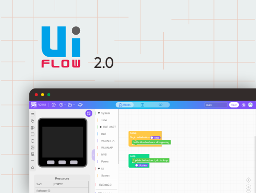
This tutorial shows you how to control the M5GO device using the UiFlow2 graphical programming platform.
This tutorial shows you how to program and control the M5GO device with the Arduino IDE.
Features
- ESP32-based development
- 16MB Flash
- Integrated full-color high-definition IPS display panel and multiple hardware peripherals
- Rich I/O interfaces, compatible with the M5Stack stacking module and sensor ecosystem, offering excellent scalability
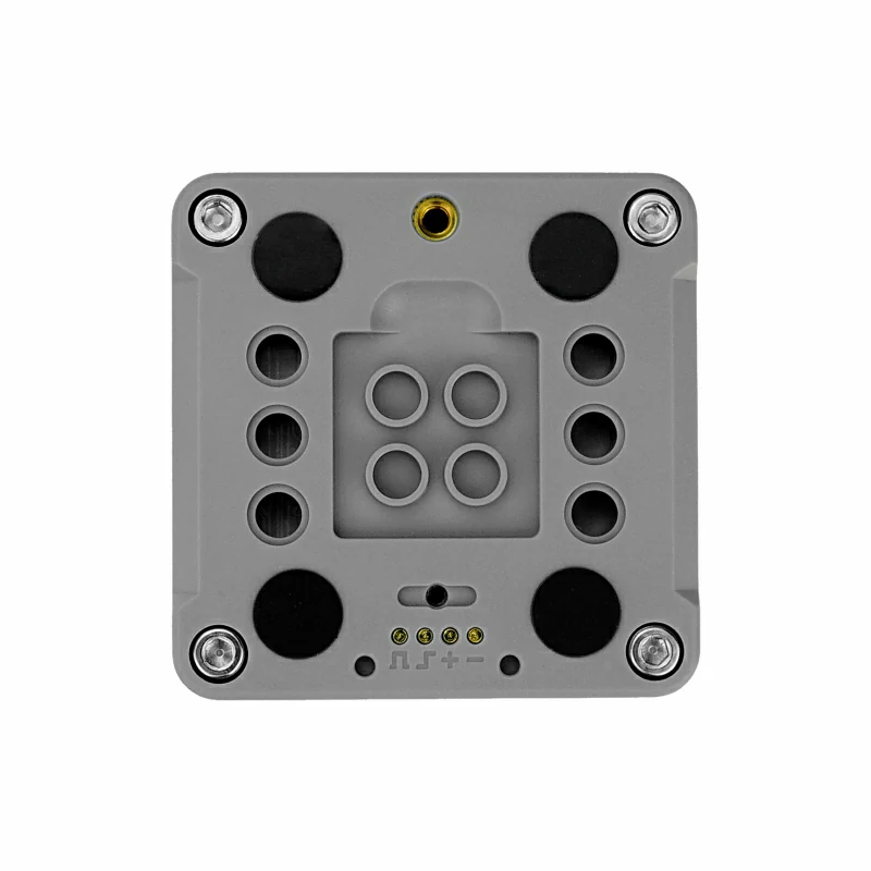
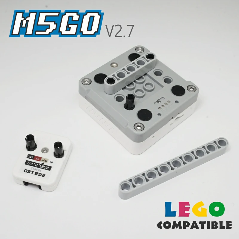
- Base shell openings compatible with 8 mm LEGO bricks for fun structural building
- Microsoft Azure Certified Device
- Development Platform
- UiFlow1
- UiFlow2
- Arduino IDE
- ESP-IDF
- PlatformIO
M5GO IoT Controller
Low-code development:
- Supports UIFlow graphical programming, scripting, compilation-free workflow, and cloud pushing
- Fully compatible with Arduino, ESP32-IDF and other mainstream development platforms
- Supports FreeRTOS; dual-core and multitasking mechanisms help organize task logic efficiently and optimize program performance
High integration:
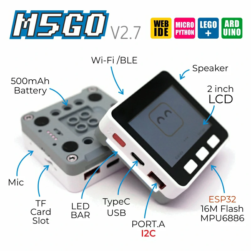
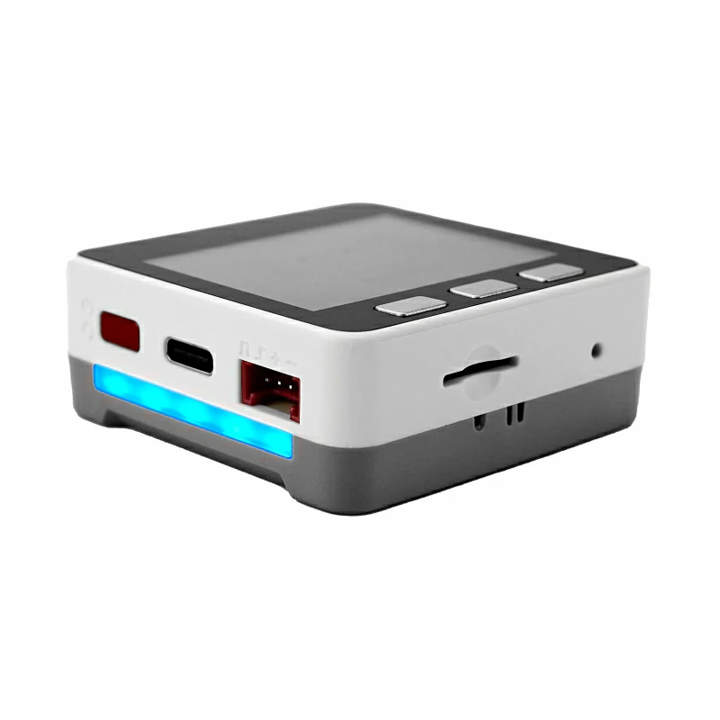
- 2.0-inch IPS display, 6-axis IMU, programmable RGB LEDs ×10, microphone, speaker, and 3 customizable buttons
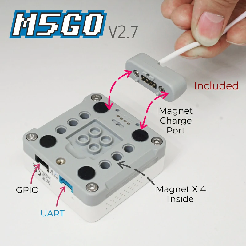
- Built-in battery, integrated power-management chip, power supply via Type-C and POGO PIN interfaces
- Professionally tuned RF circuit for stable and reliable wireless communication
Great expandability:
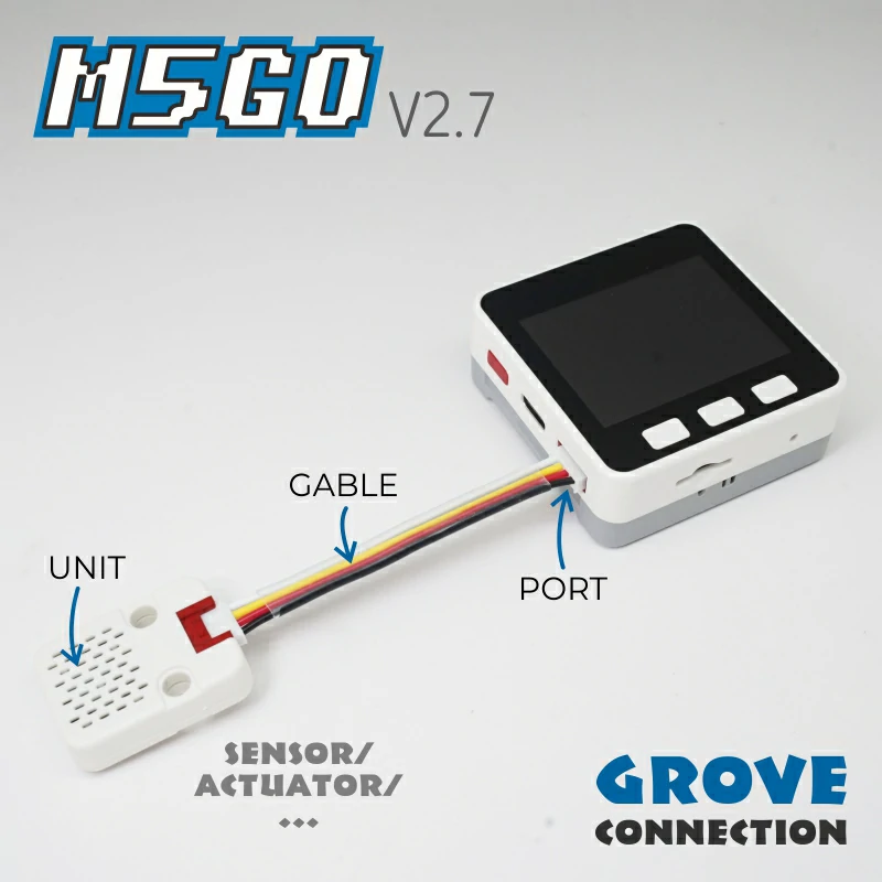
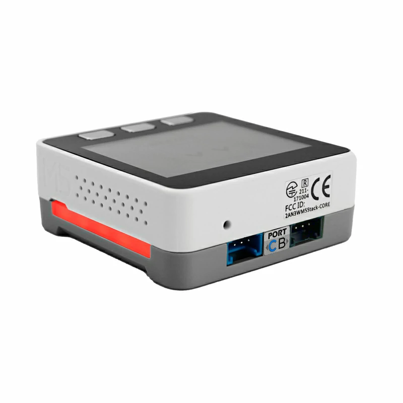
- GROVE expansion ports ×3 (I2C, GPIO, UART)
- Easily connect to the M5Stack software and hardware ecosystem, stackable module design, plug-and-play sensor expansion
6× Expansion Units
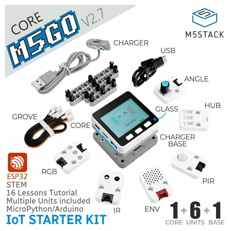
- Unit ENV-III: Temperature, humidity & barometric pressure sensor using I2C interface to quickly collect environmental data
- Unit PIR: Human body sensor, passive infrared principle for body detection, digital signal output
- Unit Angle: Rotary potentiometer, analog input for music/light adjustment
- Unit IR: Integrated infrared emitter & receiver, freely programmable for IR transmission and reception
- Unit RGB: 3× programmable RGB LEDs, support arbitrary color control via programming
- Unit Hub: I2C splitter, expands one I2C bus into three, allowing devices with different I2C addresses to be connected
Includes
- 1 × M5GO-CORE1 V2.7 main host
- 1 × M5GO BASE (charging dock)
- 1 × M5GO battery base
- 1 × M5GO charger
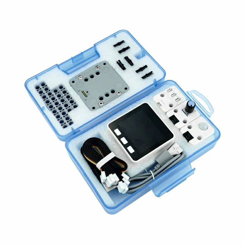
- 6 × Units (Unit ENV-III, Unit PIR, Unit Angle, Unit IR, Unit RGB, Unit Hub)
- 2 × LEGO nine-hole long plastic bricks
- 2 × LEGO five-hole long plastic bricks
- 12 × LEGO friction pins
- 2 × HY2.0-4P Grove Cables (20 cm)
- 2 × HY2.0-4P Grove Cables (10 cm)
- 1 × USB Type-C Cable (20 cm)
- 1 × M2 × 12 mm machine screw
- 1 × Hex Key L-Shape 1.5 mm (For M2 Screw)
- 1 × Quick Start Guide
Applications
- STEM education
- IoT controller
- Smart home
- Smart weather station
Specifications
| Specification | Parameter |
|---|
| SoC | ESP32-D0WDQ6-V3 @ Xtensa® 32-bit LX6 dual-core processor, clock frequency 240MHz |
| DMIPS | 600 |
| SRAM | 520KB |
| Flash | 16MB |
| Wi-Fi | 2.4 GHz Wi-Fi |
| Input Voltage | 5V@500mA |
| Host Interface | USB Type-C x1, POGO PIN x1, I2C x1, GPIO x1, UART x1 |
| IPS Display | 2 inch, 320x240 Colorful TFT LCD, ILI9342C, 853nit max brightness |
| Buttons | Custom Keys x 3 |
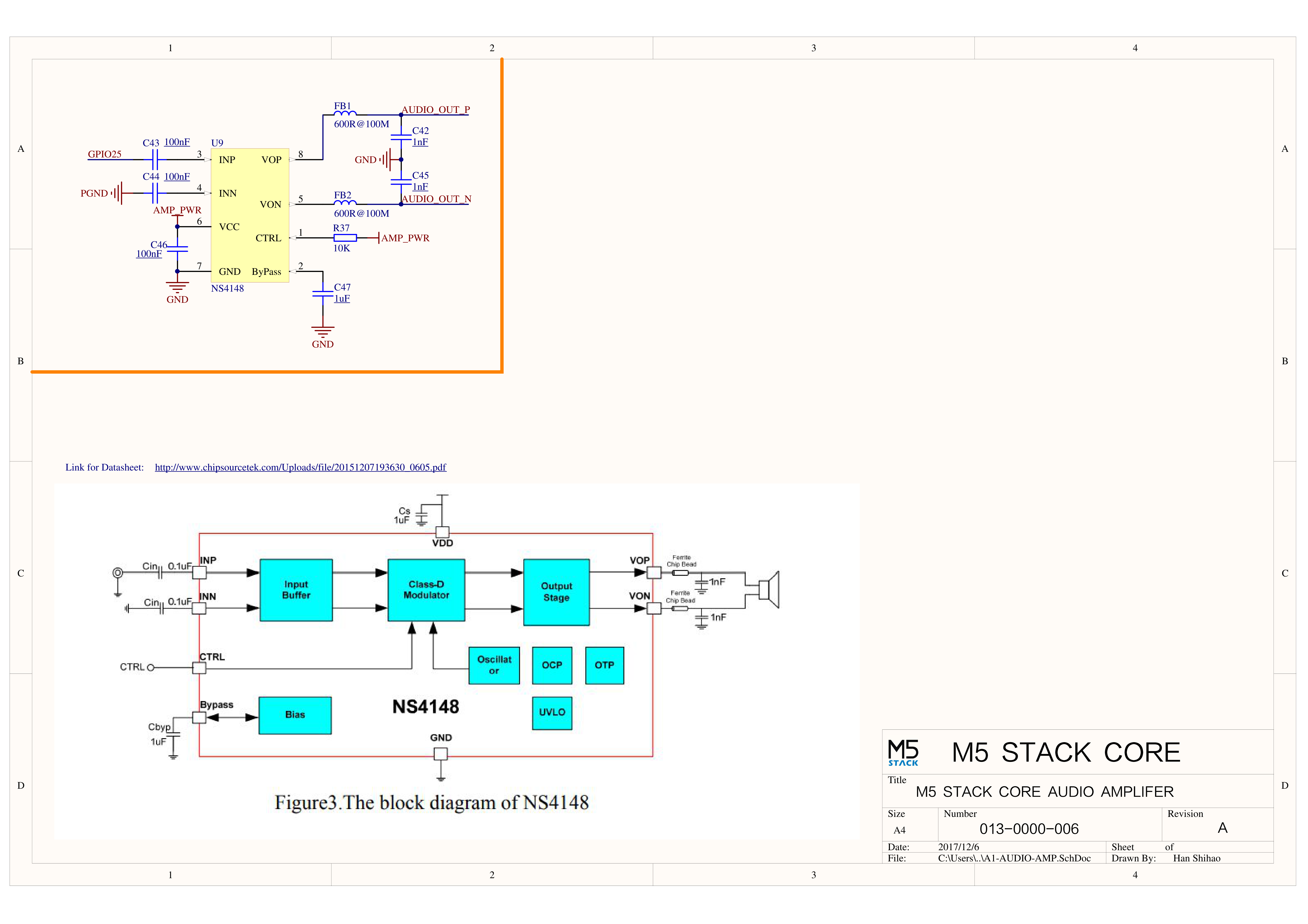
| Speaker | 1W-0928 |
| Microphone | Analog BSE3729 Microphone |
| IMU | 6-axis MPU6886 |
| USB Chip | CH9102F |
| LED | SK6812 RGB LED x 10 |
| Antenna | 2.4G 3D antenna |
| Battery | 500mAh@3.7V |
| Operating Temperature | 0 ~ 40°C |
| Case Material | Plastic (PC) |
| Product Size | 54.0 x 54.0 x 28.6mm |
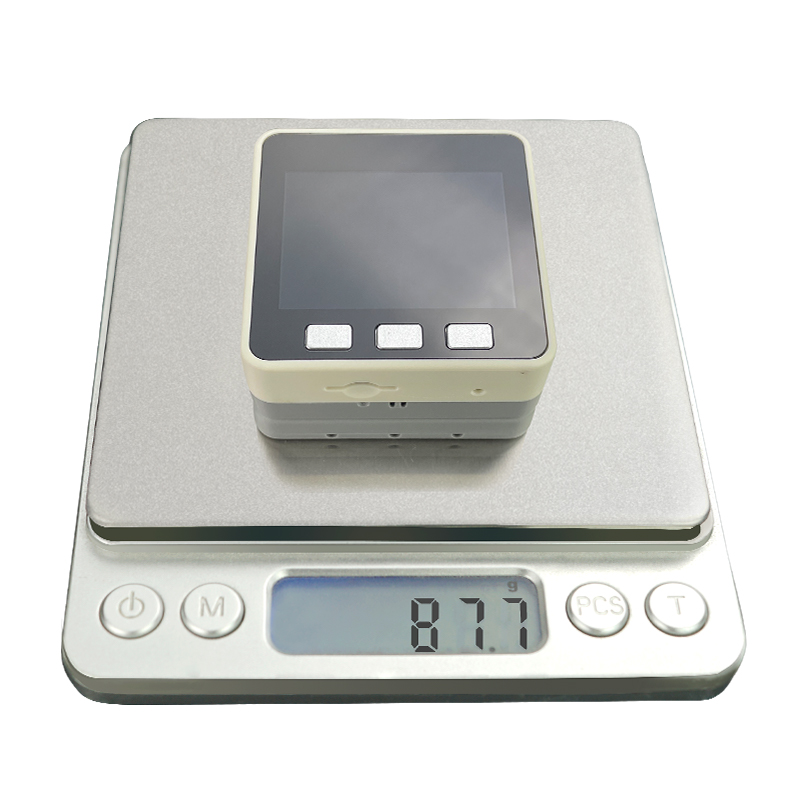
| Product Weight | 87.7g |
| Package Size | 159.3 x 91.5 x 41.1mm |
| Gross Weight | 262.5g |
Operation Instructions
Power On/Off
- Power on: single-click the red power button on the left side
- Power off: quick double-click the red power button on the left side
- USB power: by default, the device cannot be powered off while USB powered
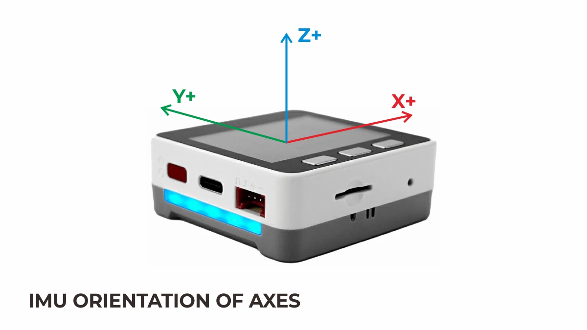
IMU Triaxial Direction Schematic Diagram
M5GO Base
Click for detailed parameters
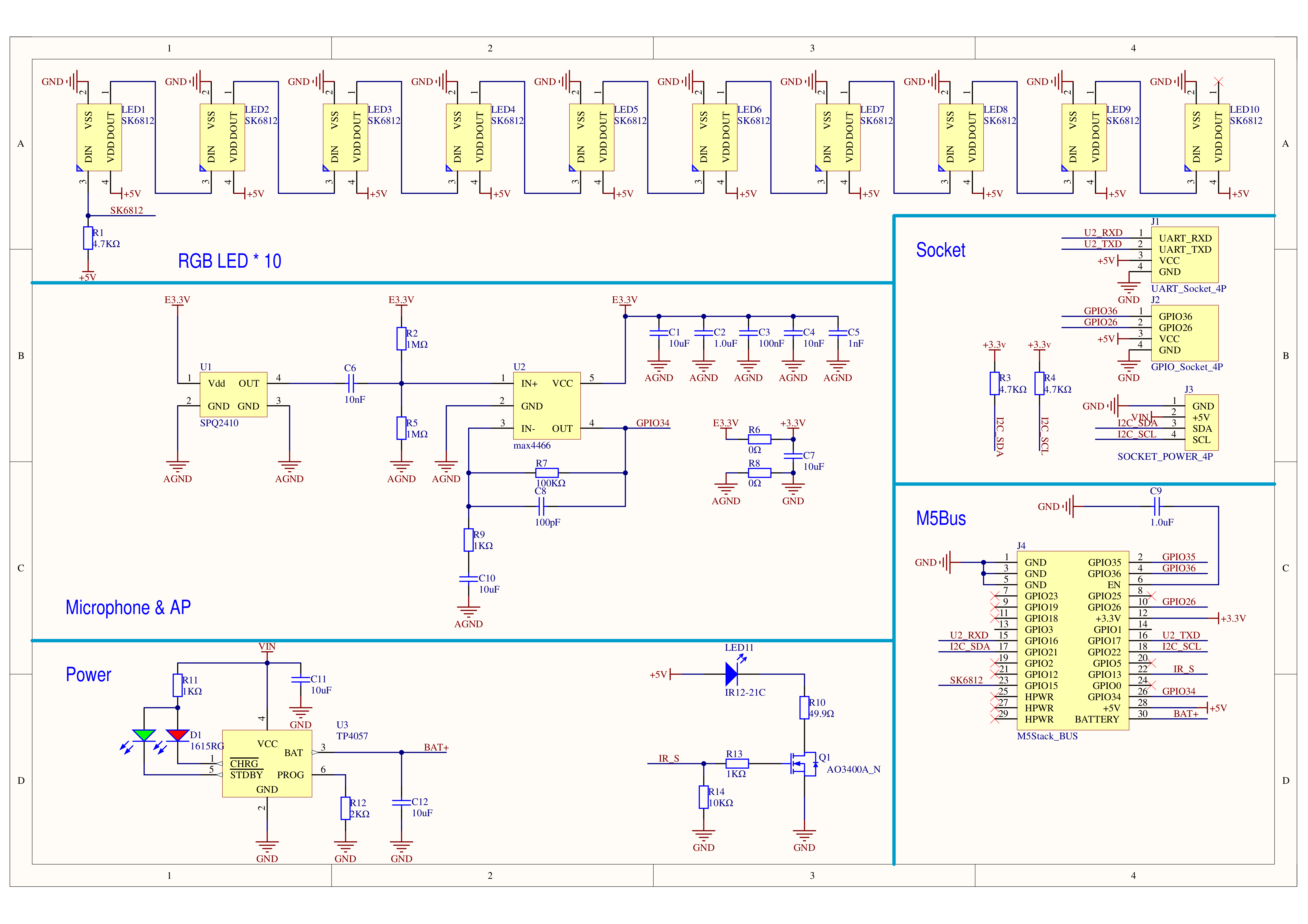
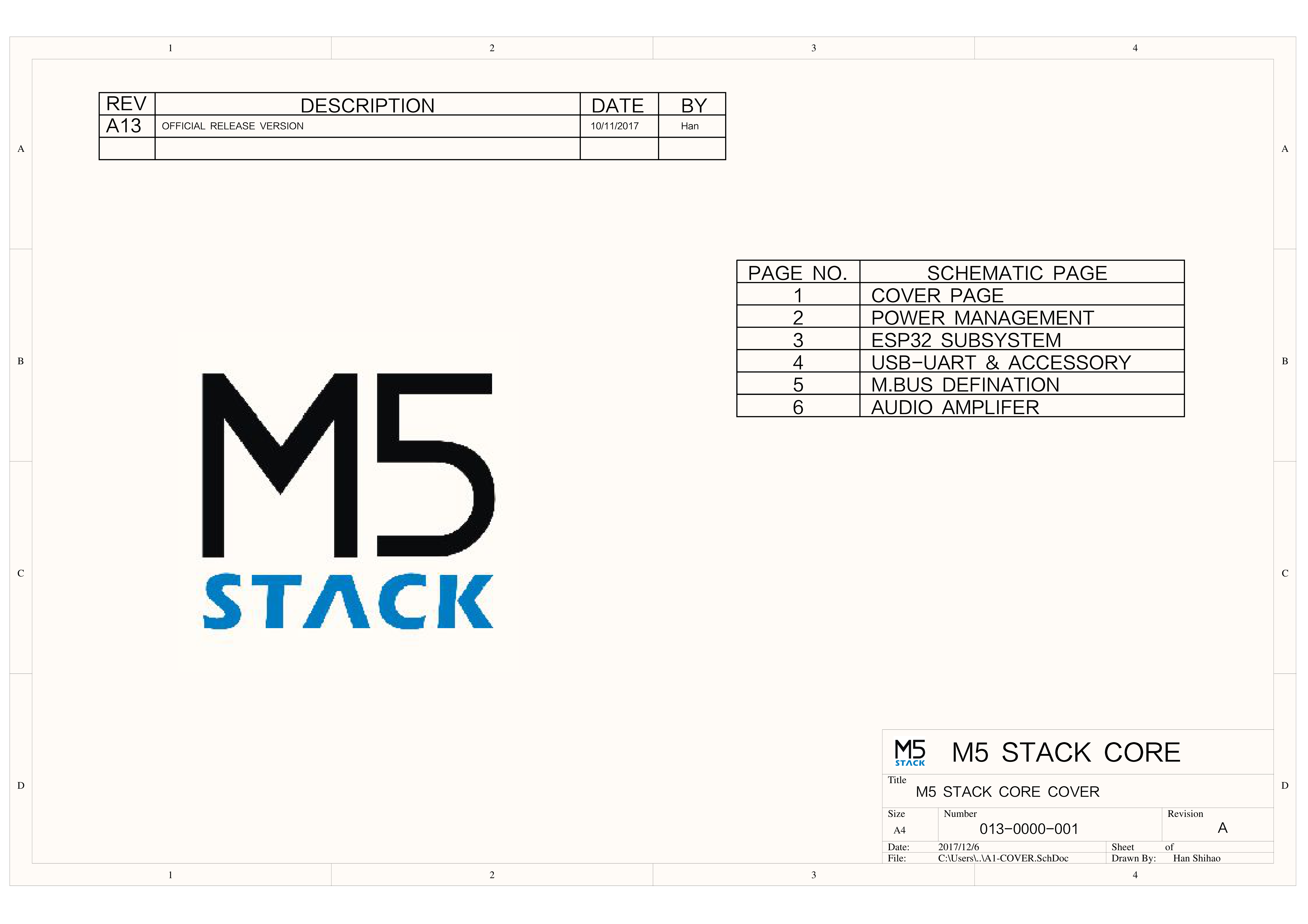
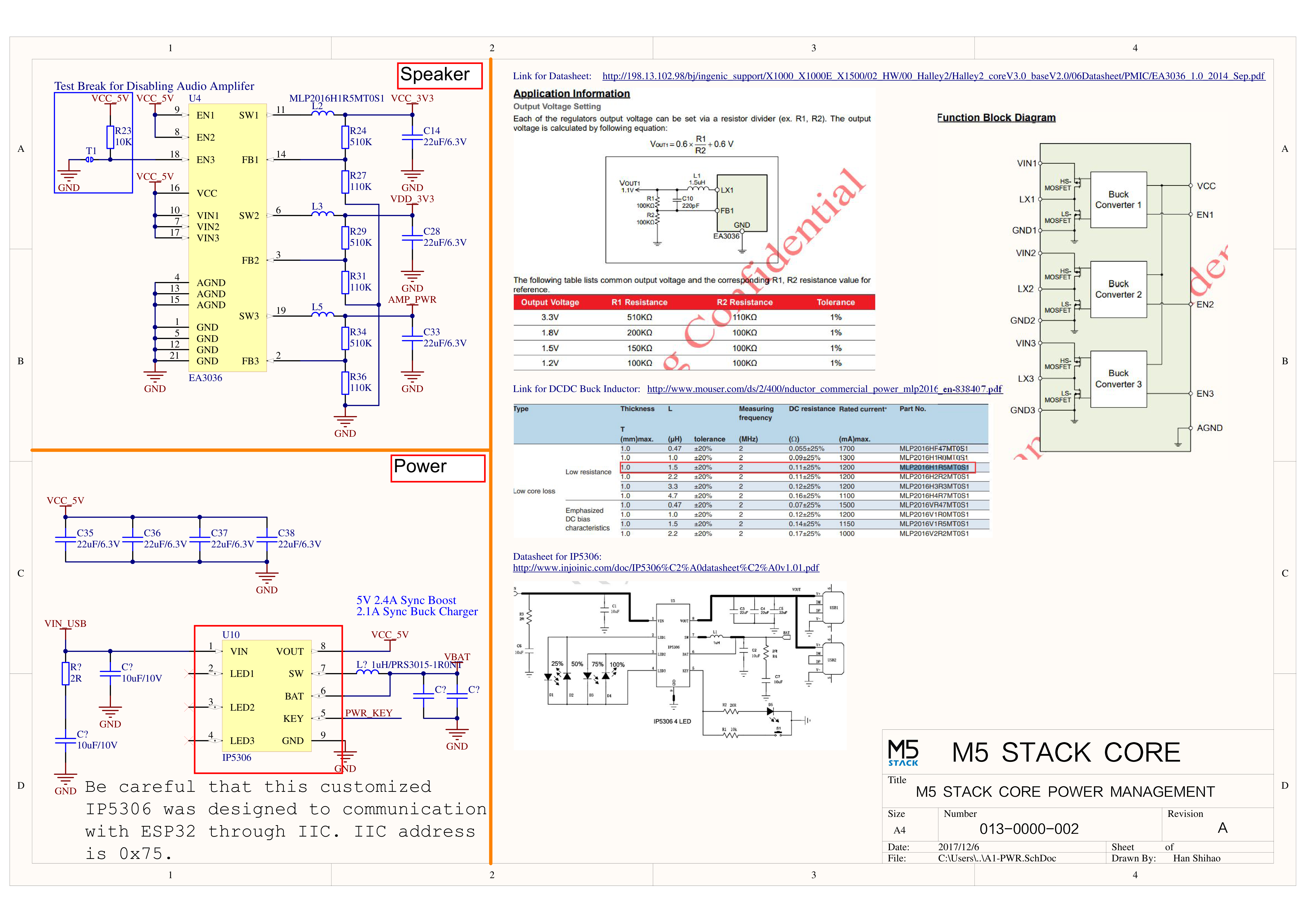
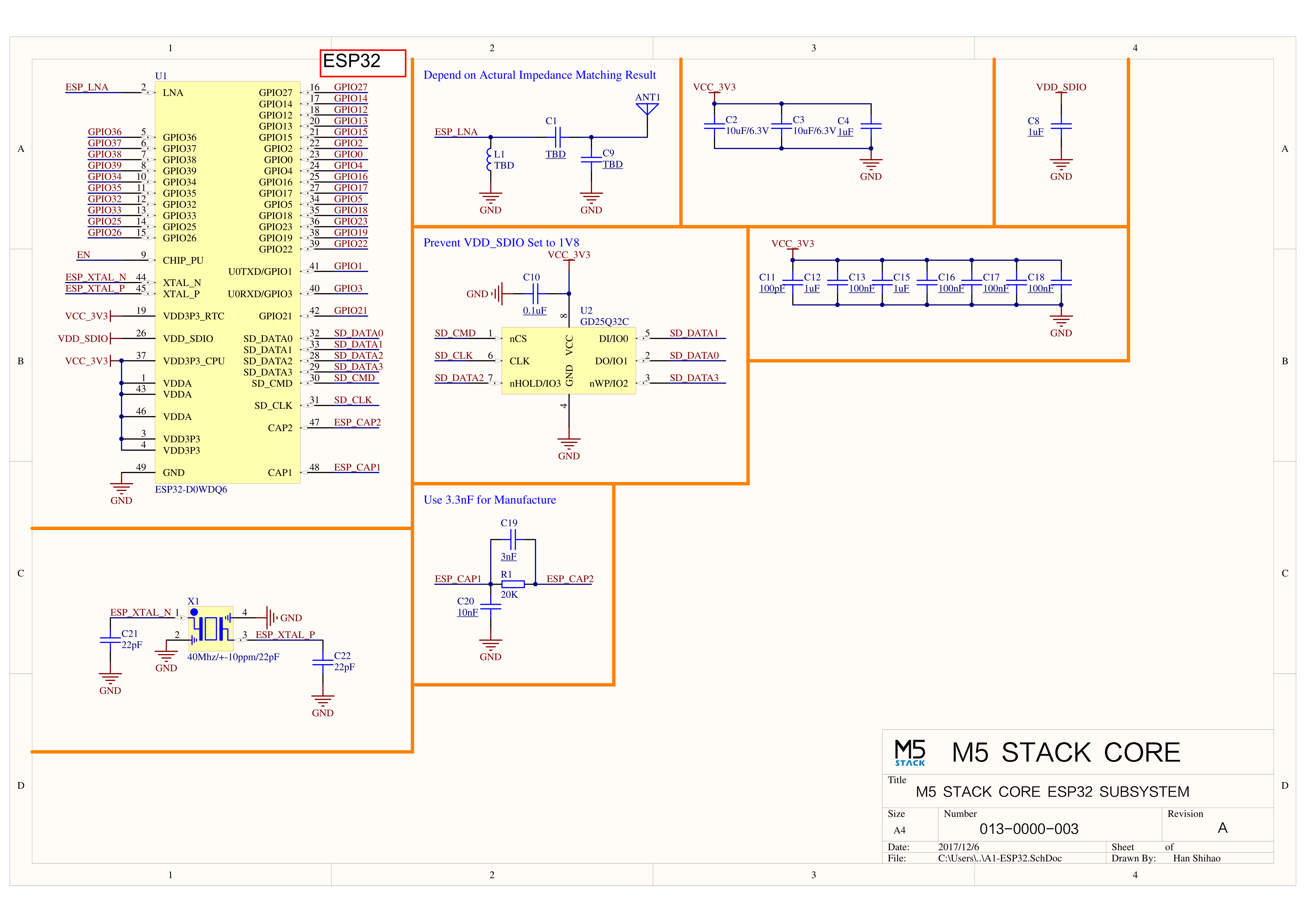
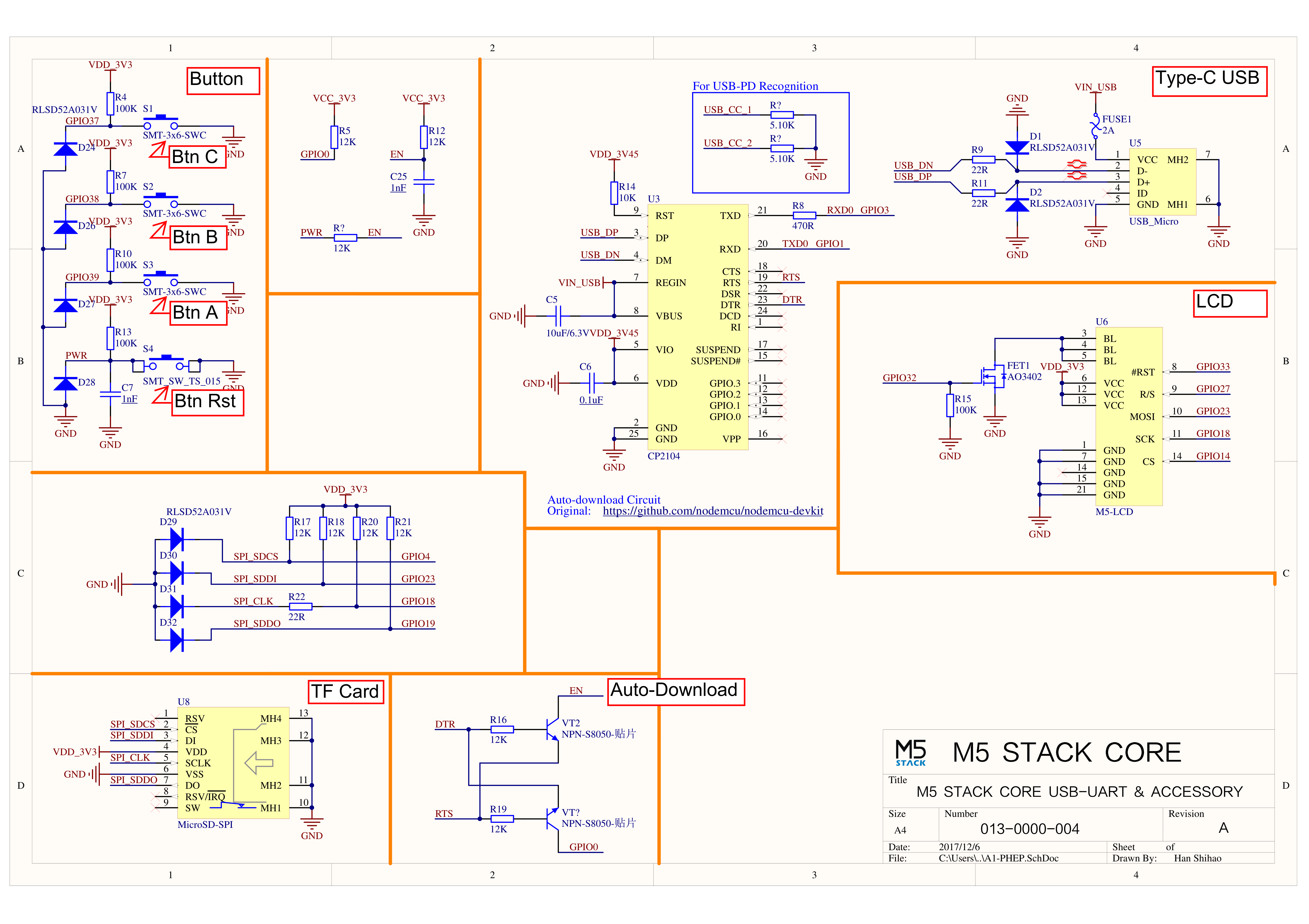
Schematics
PinMap
LCD Screen & TF Card
LCD resolution: 320 × 240
TF card supports up to 16 GB
| ESP32-D0WDQ6-V3 | G23 | G19 | G18 | G14 | G27 | G33 | G32 | G4 |
|---|
| ILI9342C | MOSI/MISO | / | CLK | CS | DC | RST | BL | |
| TF Card | MOSI | MISO | CLK | | | | | CS |
| ESP32-D0WDQ6-V3 | G39 | G38 | G37 | G25 |
|---|
| Button Pins | BUTTON A | BUTTON B | BUTTON C | |
| Speaker | | | | Speaker Pin |
GROVE Port A & IP5306
The power management chip (IP5306) is a customized I2C version with address 0x75. Click here to view the IP5306 register manual.
| ESP32-D0WDQ6-V3 | G22 | G21 | 5 V | GND |
|---|
| GROVE A | SCL | SDA | 5 V | GND |
| IP5306 (0x75) | SCL | SDA | 5 V | GND |
IP5306 Charge/Discharge Voltage Parameters
| Charging | Discharging |
|---|
| 0.00 ~ 3.40 V → 0 % | 4.20 ~ 4.07 V → 100 % |
| 3.40 ~ 3.61 V → 25 % | 4.07 ~ 3.81 V → 75 % |
| 3.61 ~ 3.88 V → 50 % | 3.81 ~ 3.55 V → 50 % |
| 3.88 ~ 4.12 V → 75 % | 3.55 ~ 3.33 V → 25 % |
| 4.12 ~ / → 100 % | 3.33 ~ 0.00 V → 0 % |
MPU6886 Gyroscope & Accelerometer
MPU6886 I2C address 0x68
| ESP32-D0WDQ6-V3 | G22 | G21 | 5 V | GND |
|---|
| MPU6886 (0x68) | SCL | SDA | 5 V | GND |
M5GO Base PinMap
LED Strip & Microphone MIC
| ESP32-D0WDQ6-V3 | G15 | G34 | G25 |
|---|
| LED Strip | Signal Pin | | |
| Microphone MIC | | MIC Pin | |
ESP32 ADC/DAC
| ADC1 | ADC2 | DAC1 | DAC2 |
|---|
| 8 ch | 10 ch | 2 ch | 2 ch |
| G32-39 | G0/2/4/12-15/25-27 | G25 | G26 |
HY2.0-4P
| HY2.0-4P | Black | Red | Yellow | White |
|---|
| PORT.A | GND | 5V | G21 | G22 |
| PORT.B | GND | 5V | G26 | G36 |
| PORT.C | GND | 5V | G17 | G16 |
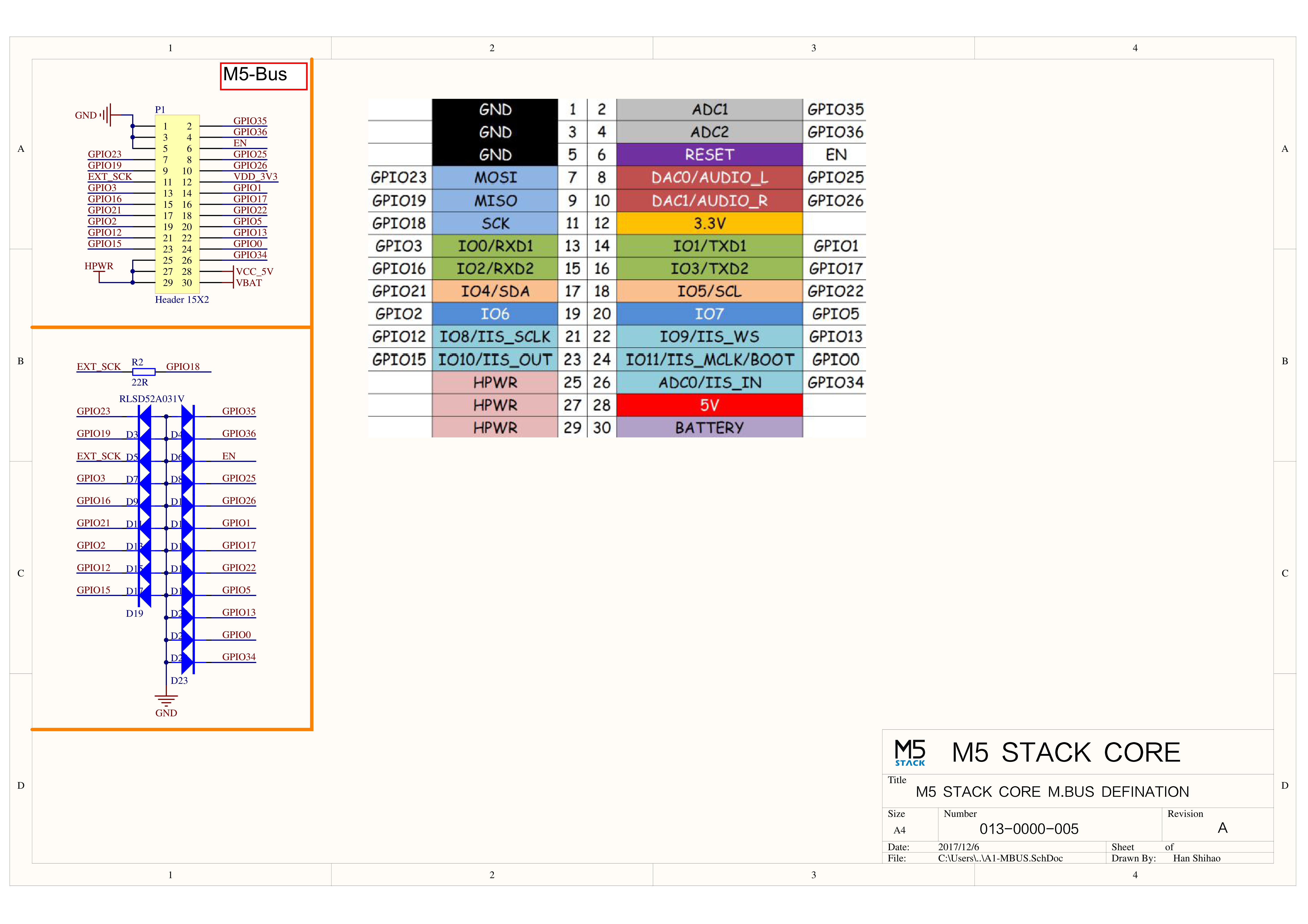
M5-Bus
| FUNC | PIN | LEFT | RIGHT | PIN | FUNC |
|---|
| GND | 1 | 2 | G35 | ADC |
| GND | 3 | 4 | G36 | ADC |
| GND | 5 | 6 | RST | EN |
| MOSI | G23 | 7 | 8 | G25 | DAC/SPK |
| MISO | G19 | 9 | 10 | G26 | DAC |
| SCK | G18 | 11 | 12 | 3V3 | |
| RXD0 | G3 | 13 | 14 | G1 | TXD0 |
| RXD2 | G16 | 15 | 16 | G17 | TXD2 |
| Int SDA | G21 | 17 | 18 | G22 | Int SCL |
| GPIO | G2 | 19 | 20 | G5 | GPIO |
| I2S_SK | G12 | 21 | 22 | G13 | I2S_WS |
| I2S_OUT | G15 | 23 | 24 | G0 | I2S_MK |
| HPWR | 25 | 26 | G34 | I2S_IN |
| HPWR | 27 | 28 | 5V | |
| HPWR | 29 | 30 | BAT | |
When using the RGB LED on G15, it is recommended to initialize the pin with pinMode(15, OUTPUT_OPEN_DRAIN).
For more information on pin assignment and remapping, please refer to the ESP32 datasheet.
Structure
Datasheets
Softwares
Arduino
UiFlow1
UiFlow2
USB Driver
Click the links below to download the driver for your operating system. Two driver chip versions are available: CP210X (for CP2104) / CP34X (for CH9102). After extracting the archive, install the package matching your OS bit-version.
(If you are unsure which USB chip your device uses, you may install both drivers. CH9102_VCP_SER_MacOS v1.7 may report an error during installation, but the driver is actually installed—just ignore the message.)
If you encounter download errors (timeout or “Failed to write to target RAM”), please try reinstalling the driver.
| Driver Name | Supported Chip | Download |
|---|
| CP210x_VCP_Windows | CP2104 | Download |
| CP210x_VCP_MacOS | CP2104 | Download |
| CP210x_VCP_Linux | CP2104 | Download |
| CH9102_VCP_SER_Windows | CH9102 | Download |
| CH9102_VCP_SER_MacOS v1.7 | CH9102 | Download |
Easyloader
EasyLoader is a lightweight firmware flasher with a built-in demo program for quick functional verification.
| Easyloader | Download | Note |
|---|
| M5GO IoT Kit v2.7 User Demo Easyloader | download | / |
Video
Demo Description: The pre-loaded UIFlow firmware includes demo programs for testing the accelerometer, LED bar, microphone, buttons, and some peripheral sensors. The firmware can be used for UIFlow graphical programming.
Product Comparison
To compare information on the controller series products, you can visit the Product Selection Table, check the target products, and get the comparison results. The selection table covers key information such as core parameters and functional features, and supports comparison of multiple products simultaneously.

Version Change
| Release Date | Product Changes | Note |
|---|
| 2023.6 | Controller upgraded to v2.7 | The screen was changed to glass for a clearer display; the Grove port added a boost function for stable 5.1V output and better load stability |
| 2023.2 | Changed packaging | / |
| 2021.8 | Upgraded to v2.6: removed BMM150 magnetometer, changed CP2104 to CH9102, optimized structural details, ENV Unit changed to Unit ENV-III | / |
| 2020.6 | ENV Unit in the kit changed to Unit ENV-II | / |
| 2019.11 | Battery capacity changed from 600mAh to 500mAh | / |
| 2019.7 | TN screen changed to IPS screen | Please upgrade your M5Stack library to the latest version (v0.2.8 or above) to solve the screen color inversion problem. |
| 2019.6 | MPU9250 changed to MPU6886+BMM150 | / |
| 2018.4 | First release | / |
Note
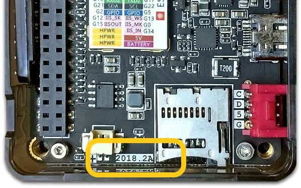
Devices with 2018.2A PCB version do not support C2C (Type-C to Type-C) connection or PD power supply.