

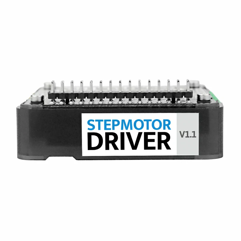
Module13.2 Stepmotor Driver v1.1
SKU:M039-V11
Description
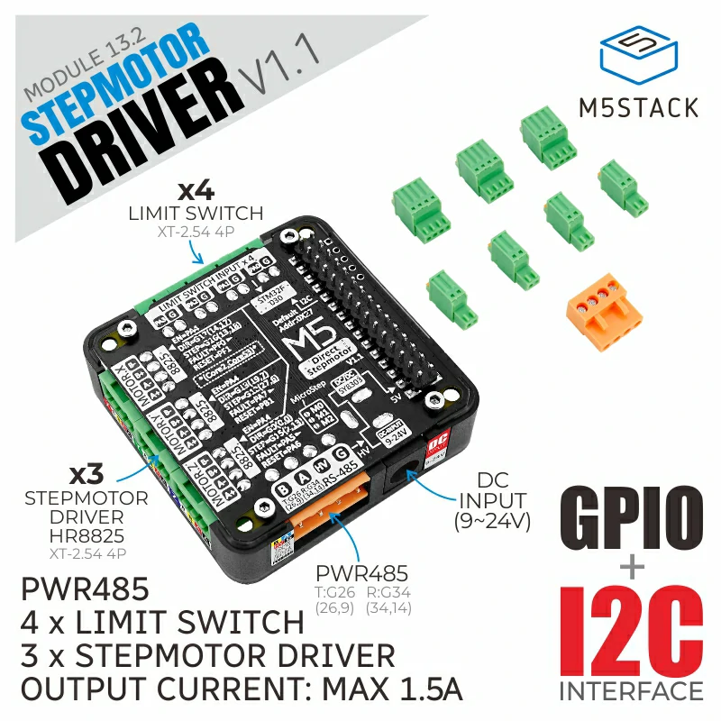
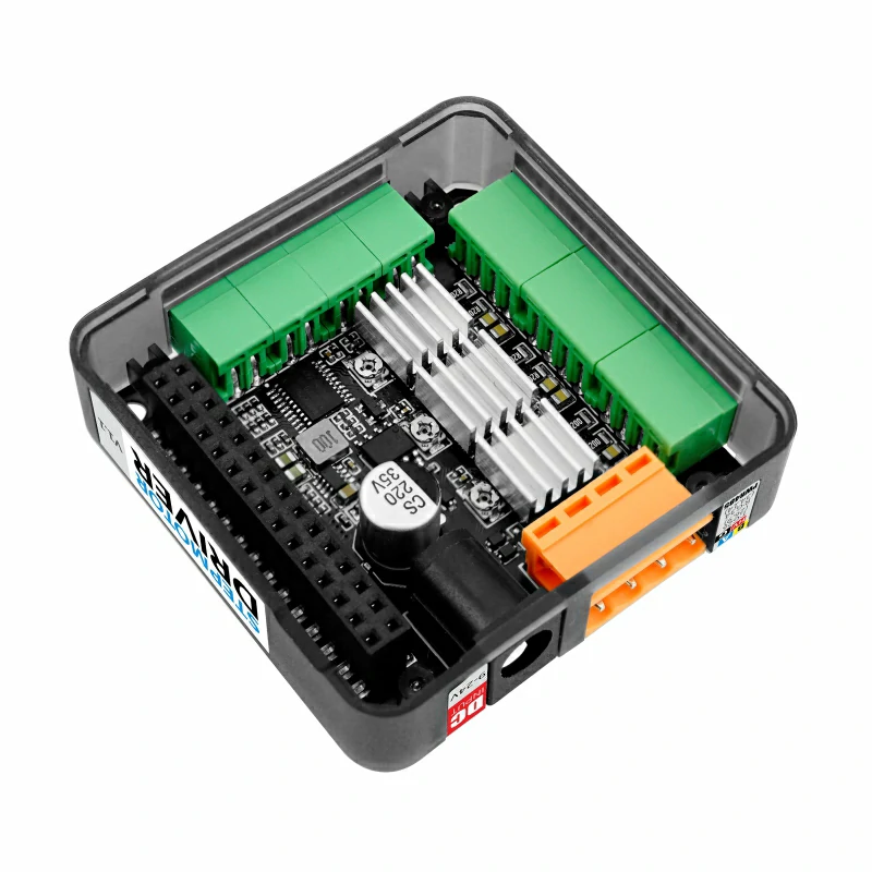
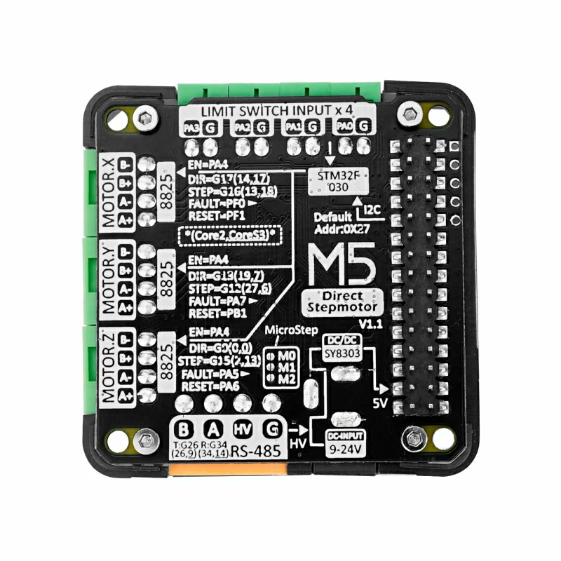
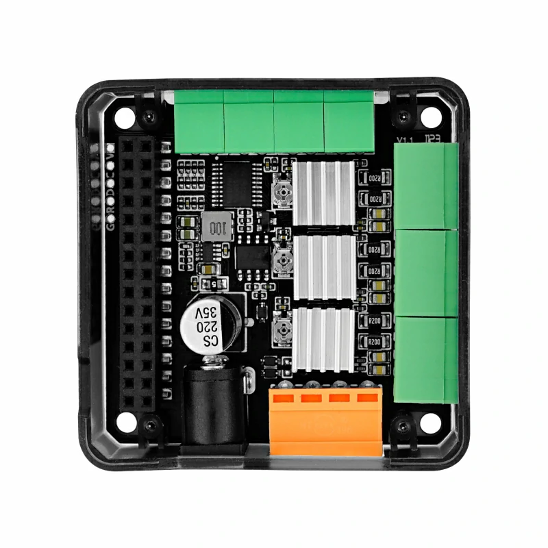
Module13.2 Stepmotor Driver v1.1 is a stepper-motor driver designed for M5 controllers, adopting an STM32 + HR8825 solution and providing three bipolar stepper-motor control ports. After stacking with an M5 controller, the on-board ESP32 directly generates signals for the driver IC, allowing either independent axis control or multi-axis linkage. An integrated STM32F030F4P6 acts as an IO expander, offering four input signal terminals and one driver-enable control, enabling I2C communication to control and monitor the driver’s reset and status, suitable for external limit switches and motor brake functions. Three solder pads on the module set the micro-stepping modes for the three motors. A built-in PWR485 communication port (RS485 + 9-24 V power input) and a DC-JACK provide flexible power options while communicating. UIFlow graphical programming is supported for easy signal configuration and precise stepper-motor control. The module fits various motion-control scenarios such as printers and robotic arms.
Note
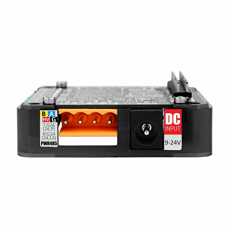
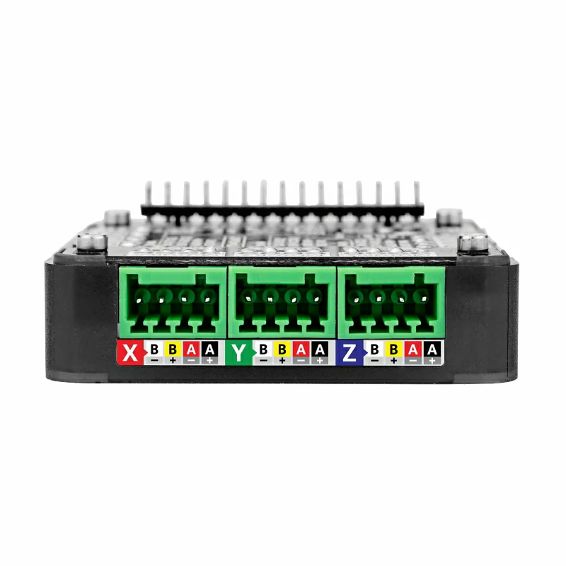
- Connector Type: 3.96-4P terminal
- Voltage Range: DC 9 ~ 24V
2. DC Jack:
- Voltage Range: DC 9 ~ 24V
- Connector Type: 5.5/2.1mm DC jack
- Polarity: Center positive, outer negative
Features
- STM32F030F4P6@: ARM® 32-bit Cortex™-M0 CPU
- Triple-axis HR8825 stepper-motor drivers
- Suitable for bipolar stepper motors
- Adjustable potentiometer per channel, drive current up to 1.5 A
- Multiple micro-stepping modes, up to 1/32 STEP
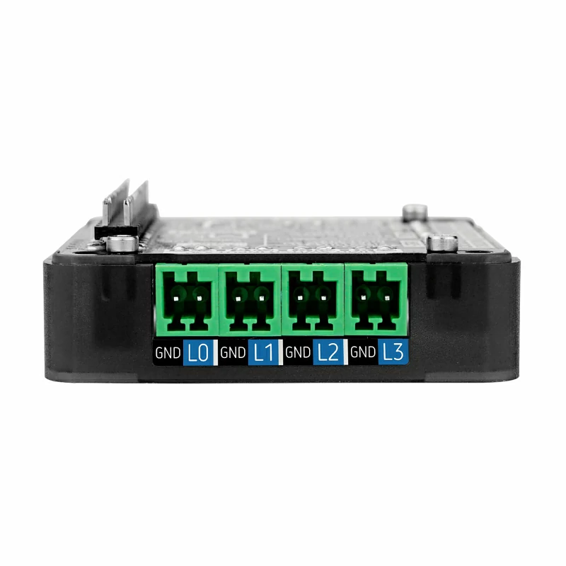
- Four signal-input interfaces
- PWR485 communication port (RS485 + 9-24 V power input)
- DC-JACK input (9-24 V)
- Development Platform: Arduino, UIFlow
Includes
- 1 x Module13.2 Stepmotor Driver v1.1
- 4 x 2.54-2P Terminal
- 3 x 2.54-4P Terminal
- 1 x 3.96-4P Terminal
Applications
- Printers
- Scanners
- CNC engraver control
- Motion-module control
Specifications
| Specification | Parameter |
|---|---|
| IO Expander | STM32F030F4P6 |
| Stepper-motor Driver IC | HR8825 |
| Communication Interface | I2C Communication @0x27 |
| Supported Micro-step Modes | FULL, 1/2, 1/4, 1/8, 1/16, 1/32 |
| Max Drive Current / Channel | 1.5 A |
| Input-signal Terminal | 2.54-2P |
| Motor Power Supply | DC 9-24 V (5.5/2.1 mm DC jack) Voltage range: DC 9-24 V Interface type: 5.5/2.1 mm DC jack Polarity: center + |
| Motor Terminal Specification | 2.54-4P |
| RS485 Terminal Specification | 3.96-4P (9-12 V) |
| Operating Temperature | 0-40 °C |
| Product Size | 54.0 x 54.0 x 19.7mm |
| Package Size | 95 x 65 x 25mm |
| Product Weight | 40g |
| Gross Weight | 60g |
Learn
Subdivision/Micro-step Truth Table
| M2 | M1 | M0 | Resolution |
|---|---|---|---|
| 0 | 0 | 0 | FULL |
| 0 | 0 | 1 | 1/2 |
| 0 | 1 | 0 | 1/4 |
| 0 | 1 | 1 | 1/8 |
| 1 | 0 | 0 | 1/16 |
| 1 | 0 | 1 | 1/32 |
| 1 | 1 | 0 | 1/32 |
| 1 | 1 | 1 | 1/32 |
Set the desired micro-step mode by soldering the corresponding pad to logic 1.\ 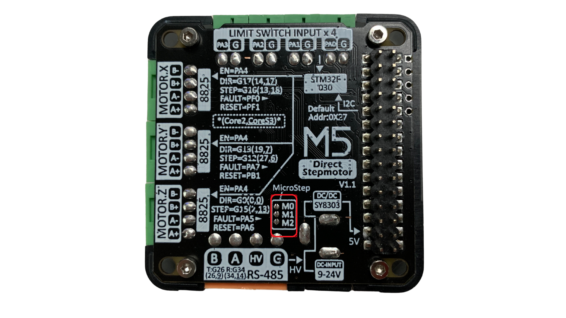
Drive Current Adjustment
Different stepper motors require different drive currents. You can adjust the output current with the metal trimmer on the module. To avoid overheating or damaging the motor, turn the trimmer slowly and observe motor behavior or use an ammeter to determine the proper current.\ 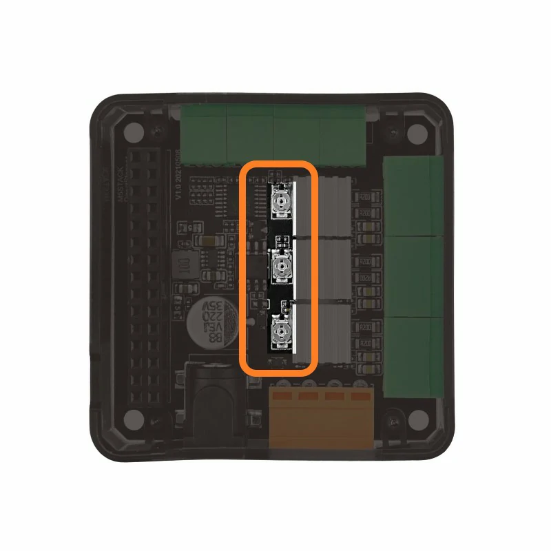
Schematics
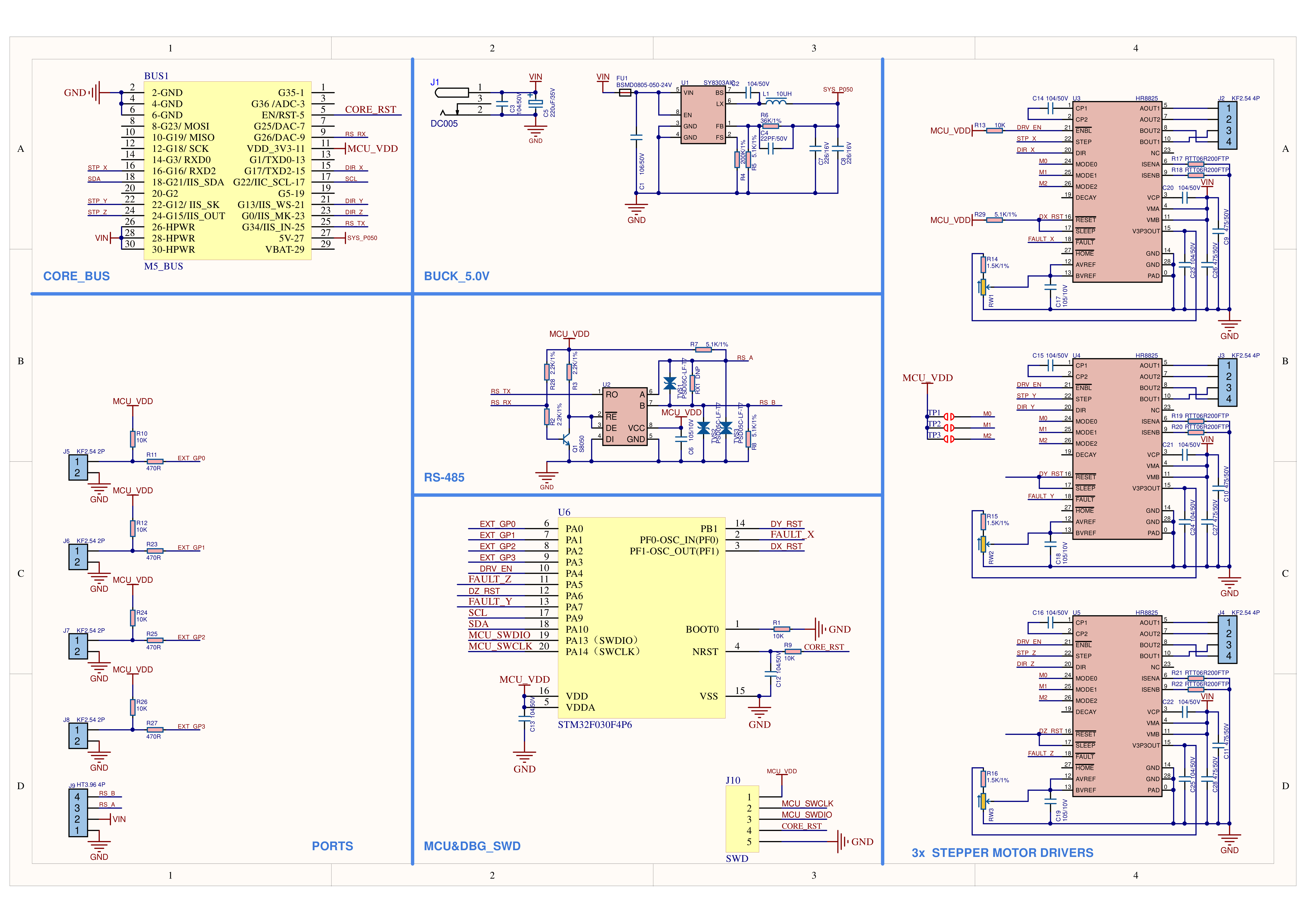
PinMap
.png)
M5-Bus
| PIN | LEFT | RIGHT | PIN |
|---|---|---|---|
| GND | 1 | 2 | |
| GND | 3 | 4 | |
| GND | 5 | 6 | |
| 7 | 8 | RS485_TX | |
| 9 | 10 | ||
| 11 | 12 | 3V3 | |
| 13 | 14 | ||
| STEP_X | 15 | 16 | DIR_X |
| SDA | 17 | 18 | SCL |
| 19 | 20 | ||
| STEP_Y | 21 | 22 | DIR_Y |
| STEP_Z | 23 | 24 | DIR_Z |
| HPWR | 25 | 26 | RS485_RX |
| HPWR | 27 | 28 | 5V |
| HPWR | 29 | 30 |
Model Size
Datasheets
Softwares
Arduino
UiFlow1
UiFlow2
Internal Firmware
Protocol
Video
Product Comparison
| Product Compare | GRBL 13.2 MODULE  | STEPMOTOR DRIVER  | STEPMOTOR DRIVER V1.1 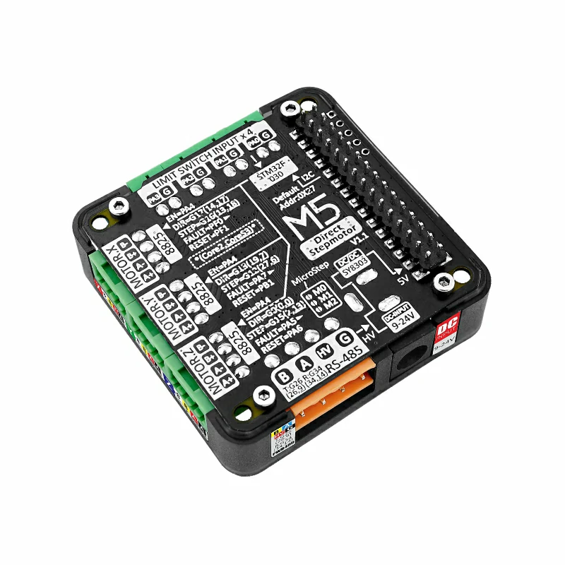 |
|---|---|---|---|
| Control Method | Pulse Signal | Pulse Signal | Pulse Signal |
| MCU | On-board MEGA328 | Directly controlled by Core host | On-board STM32F030F4P6 |
| I2C Chip-select | I2C (0x70 , 0x71) | / | / |
| Stackable Qty | 2 | 1 | 1 |
| Driver IC | DRV8825 | HR8825 | HR8825 |
| Micro-step Adj. | DIP Switch | Controlled by TCA9554 | Solder-pad selection |
| Interface | DC power port + 3 limit-switch ports | DC power port + 4 custom input ports + RS485 port | DC power port + 4 custom input ports + RS485 port |
| Stepper Port | 3 x XH2.54-4P | 3 x XH2.54-4P | 3 x XH2.54-4P |