Base26
SKU:K026
Description
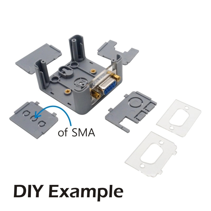
Base26 is a highly customizable industrial base in the M5 ecosystem. It is similar to the PLC Base but provides a higher level of customization. The kit includes a protoboard (universal board) that allows you to add your own circuit design, and it reserves solder pads for two Grove interfaces to conveniently expand circuits. It also includes a TTL/RS485 adapter board, making RS485 level conversion easy, as well as M-type waterproof connector components, which can be installed on the side or bottom of the base. The "26" in Base26 refers to the base height of 26mm, with each side of the base being freely detachable, cuttable, and customizable into different interfaces to meet various requirements. For base customization, we provide a large number of alternative structural components and have made them fully open-source, enabling you to create 3D printed parts or perform secondary designs based on them. Furthermore, the base is fully compatible with the M5 stackable modules and hardware expansion system. On the bottom of the product, we offer two different mounting options: rail mounting and suspended mounting. The base features an industrial-grade shell, and its freely combinable components provide you with unlimited combination possibilities, allowing you to create powerful and reliable industrial applications. For developers targeting industrial scenarios that require a certain level of protection and highly customized projects, Base26 is an excellent solution.
Features
Supports high customization
Replaceable parts
M5-Bus expansion
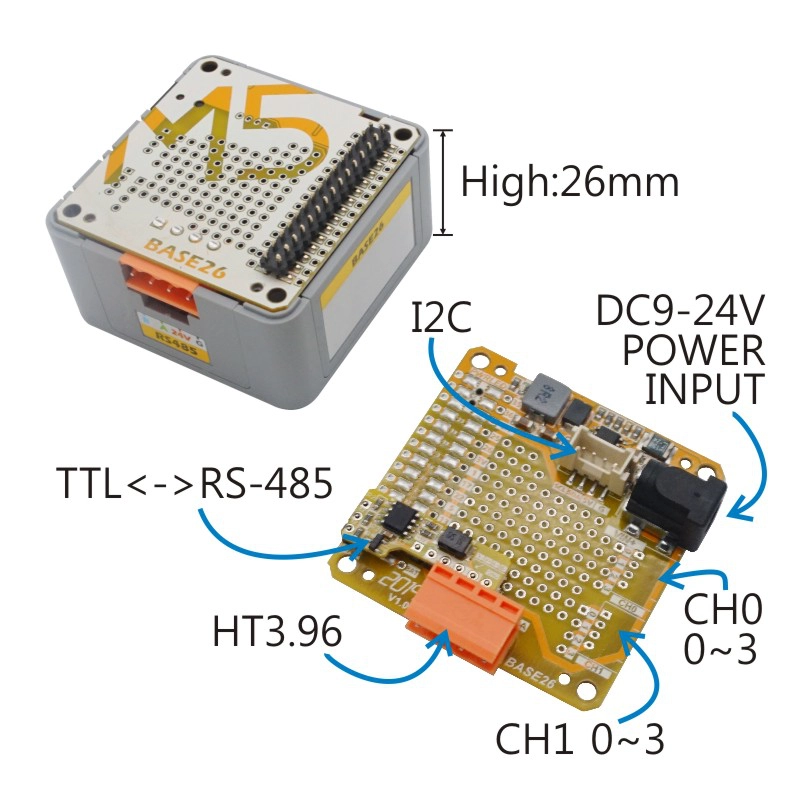
Onboard DC-DC conversion (9 ~ 24V -> 5V)
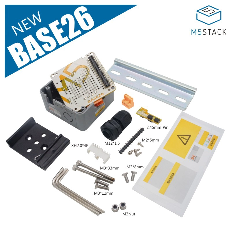
Includes
- 1 x Base26 Proto Board
- 1 x Base26 Base Enclosure
- 1 x RS485-to-TTL Adapter Board
- 2 x HY2.0-4P Terminal
- 1 x Hex Key L-Shape 1.5mm (For M2 Screw)
- 1 x Hex Key L-Shape 2.0mm (For M2.5 Screw)
- 1 x Hex Key L-Shape 2.5mm (For M3 Screw)
- 1 x 35mm Silver Metal DIN Rail
- 1 x 35mm Black DIN Rail Clip
- 2 x M3 * 8mm Countersunk Machine Screw
- 2 x M3 * 22mm Cap Head Machine Screw
- 4 x M2 * 5mm Cap Head Self-Tapping Screw
- 1 x Cable Gland (M12)
- 2 x M3 Nut (with Anti-Slip Nylon Ring)
- 1 x 2.54mm-20P Straight Male Header (Overall Height 5.32mm)
- 1 x HT3.96-4P Terminal
- 1 x Product Sticker
Specifications
| Specification | Parameter |
|---|---|
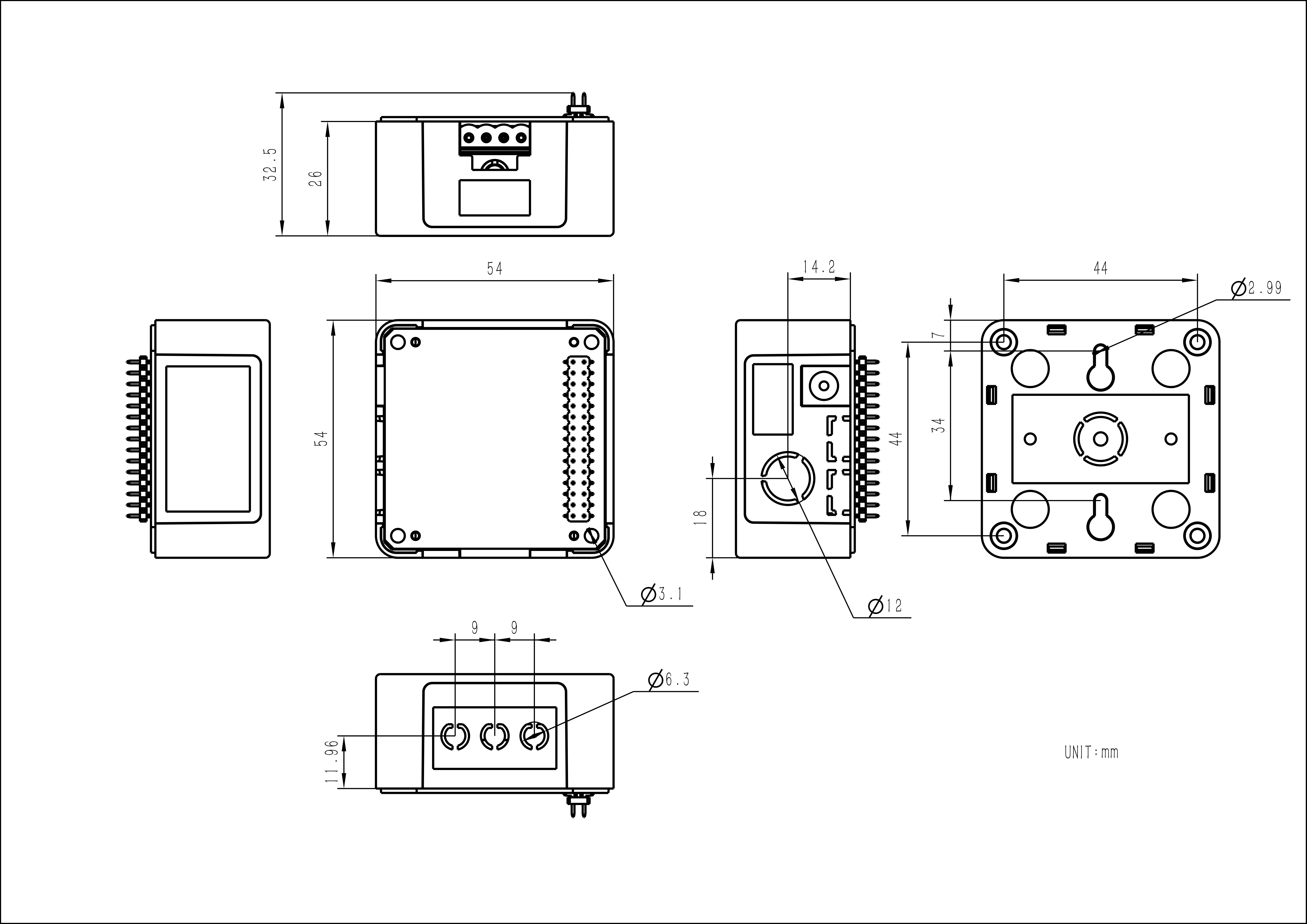
| Product Size | 54 x 54 x 26mm |
| Product Weight | 27g |
| Package Size | 125 x 67 x 23mm |
| Gross Weight | 125g |
Schematics
PinMap
M5-Bus
| PIN | LEFT | RIGHT | PIN |
|---|---|---|---|
| GND | 1 | 2 | NC |
| GND | 3 | 4 | NC |
| GND | 5 | 6 | EN |
| NC | 7 | 8 | NC |
| NC | 9 | 10 | NC |
| NC | 11 | 12 | 3V3 |
| NC | 13 | 14 | NC |
| NC | 15 | 16 | NC |
| SDA | 17 | 18 | SCL |
| NC | 19 | 20 | NC |
| NC | 21 | 22 | NC |
| NC | 23 | 24 | NC |
| HPWR | 25 | 26 | NC |
| HPWR | 27 | 28 | 5V |
| HPWR | 29 | 30 | BAT |
Model Size