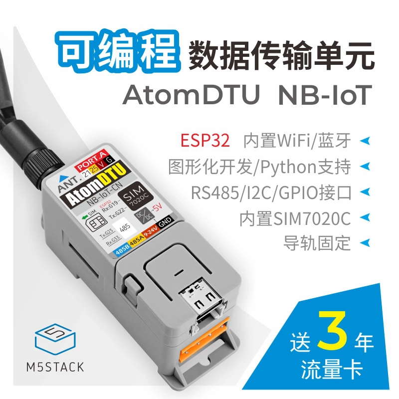
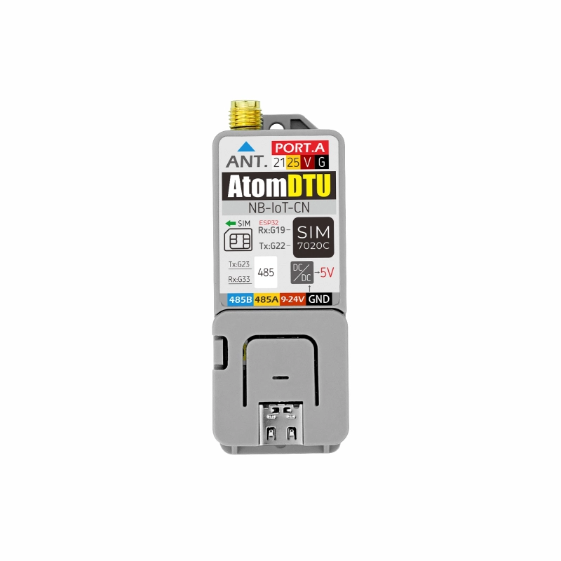
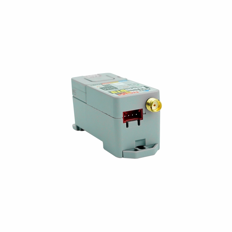
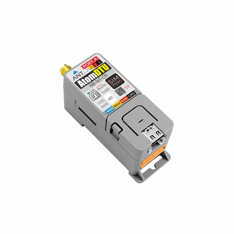
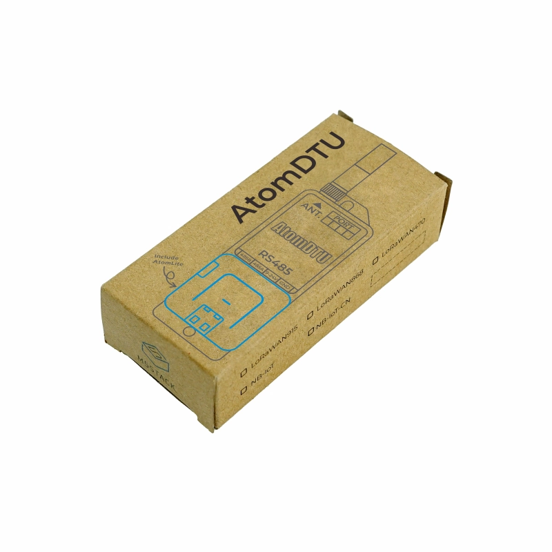
Atom DTU NBIoT-CN is a programmable data transmission unit (DTU) integrated with NB-IoT communication functionality. It comes with a built-in SIM7020C module, covering most Cat-NB frequency bands, and features an SMA external antenna interface to enhance communication quality and signal stability. Unlike conventional DTUs that only offer data passthrough, the Atom DTU NBIoT-CN series adopts a more open architecture design. The Atom-Lite controller allows for flexible program modifications based on actual business needs, and the device is equipped with multiple interfaces (RS485, I2C, custom interfaces) for user expansion, facilitating quick integration of sensors and actuators. With its built-in rail mounting structure, it seamlessly integrates into various industrial control environments. The Atom DTU NBIoT-CN is ideal for low-latency, low-throughput applications such as remote control, asset tracking, remote monitoring, telemedicine, and shared bikes.
Features
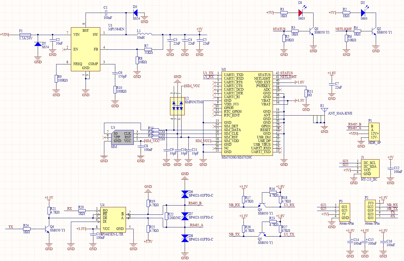
SIM7020C/Suitable for China
RS485 communication interface (with 12V input, internally integrated DC-DC step-down to 5V)
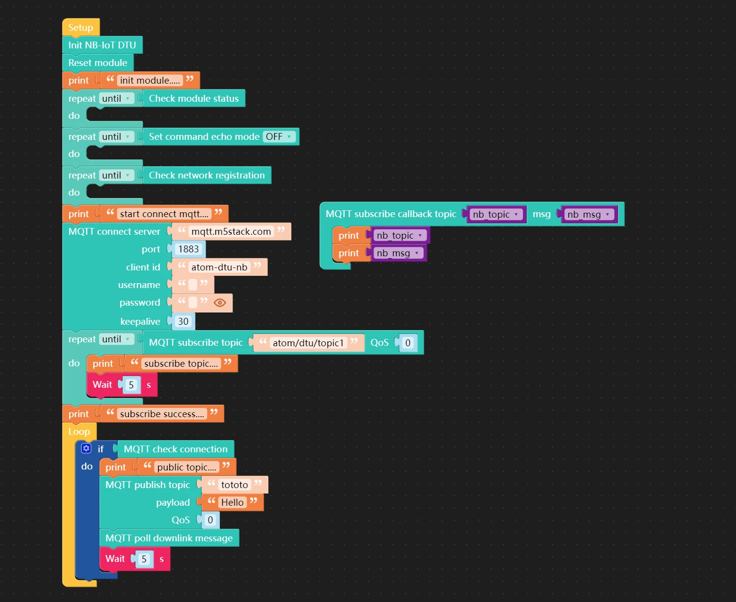
Connect to the MQTT server to perform message subscription and publishing. When a new subscribed message is received, the callback function is invoked with the topic name and data content passed in, and the output result is printed to the USB serial port.