Base DMX
SKU:M128
Description
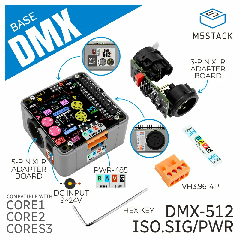
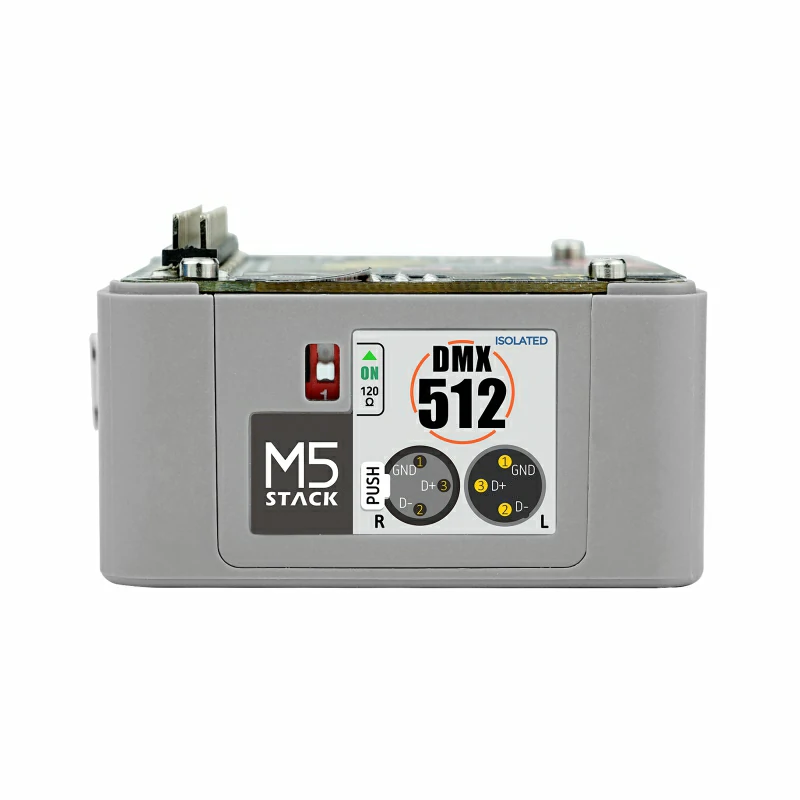
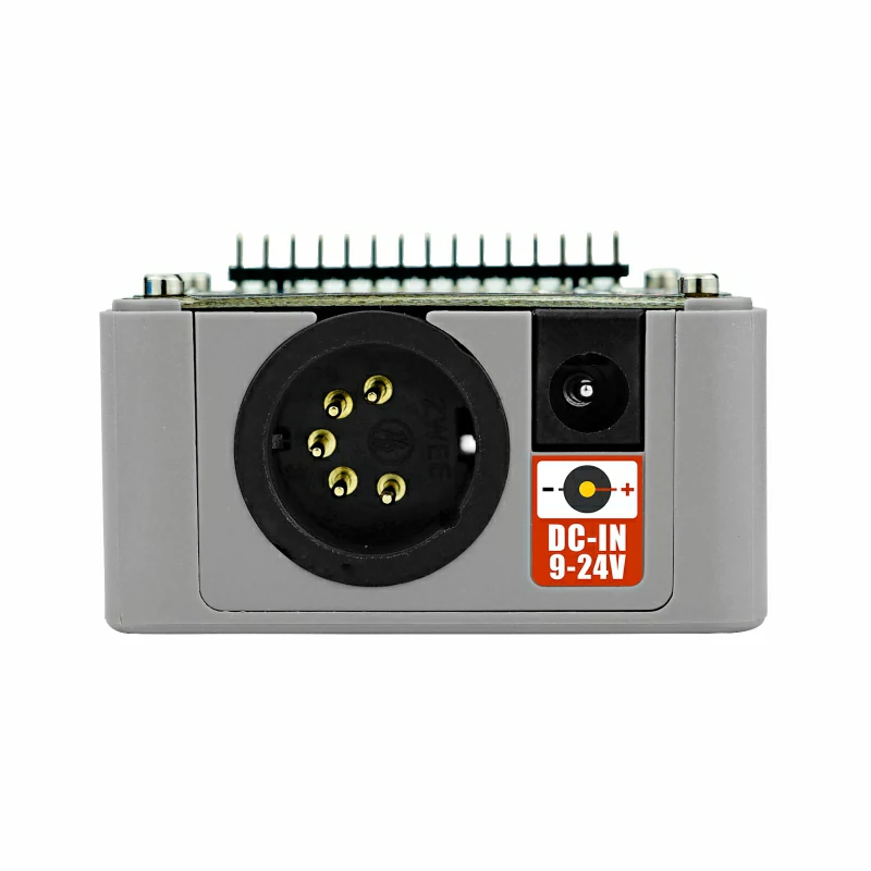
Base DMX is a functional base specifically designed for DMX-512 data transmission scenarios. It communicates and enables control with the M5 host via a serial port and comes equipped with both male and female XLR-5 and XLR-3 connectors to facilitate connections to DMX devices with different interfaces. In addition, the module features a 485 interface with HT3.96 pitch for connecting to extended 485 devices. Communication signals are transmitted through high-speed opto-isolation, and the power supply adopts a dedicated isolated power module. It provides two independent RS-485 circuits for transmitting and receiving DMX data, with an internal double-pole switch allowing the operation of two independent lines or parallel connections. For power supply, the DC-JACK interface and its corresponding DC-DC circuit can power the entire device. This product is suitable for stage lighting control, sound equipment control, landscape lighting control, and decorative lighting control.
Features
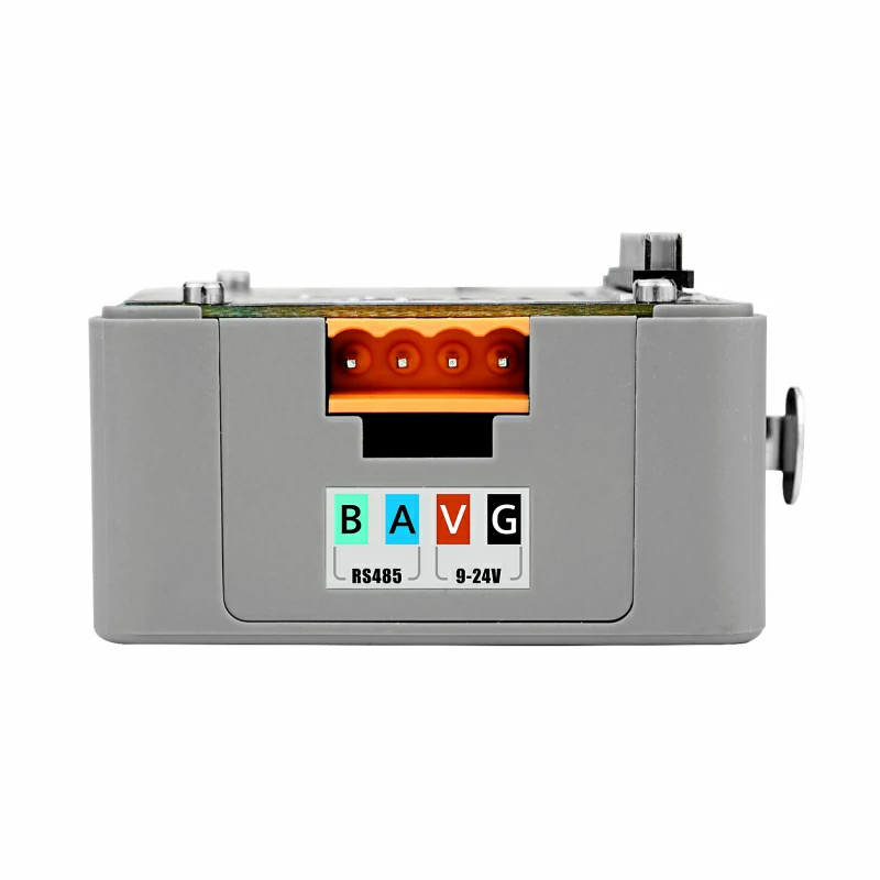
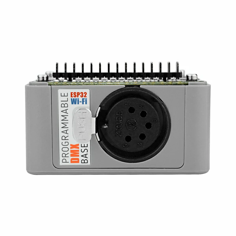
- Equipped with both male and female XLR-5 and XLR-3 connectors for DMX device connections
- Supports communication and enable control with M5 host via serial port
- Built-in two double-pole switches to control connection mode and transmission path
- Uses DC-DC isolated power supply to improve stability and consistency
- Development Platform:
- Arduino
- UIFlow
Includes
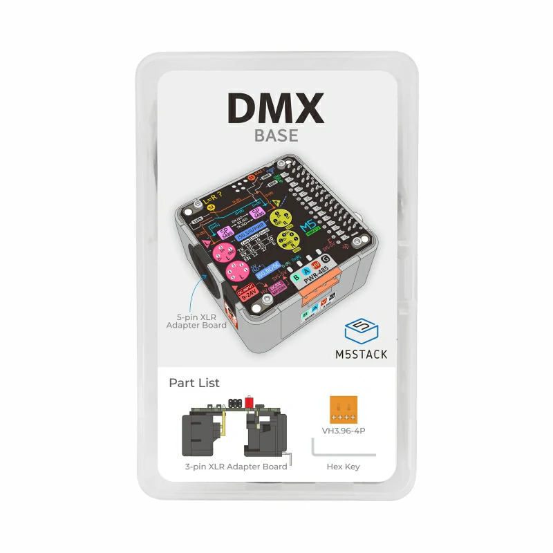
- 1 x Base DMX
- 1 x Hex Key L-Shape 2.0mm (For M2.5 Screw)
- 1 x HT3.96-4P Terminal
- 1 x XLR-3 Connector
Applications
- Stage lighting control
- Sound equipment control
- Landscape lighting control
- Decorative lighting control
Specifications
| Specification | Parameter |
|---|---|
| 485 Communication | SP3488EN |
| Optocoupler Isolation High-speed Transmission | EL0600EL0631 |
| DC-DC | MP1584EN |
| Voltage Isolation | B0505LS-1WR2 |
| Voltage Input | DC 9 ~ 24V |
| DMX Interface | XLR-5, XLR-3 male/female connectors |
| 485 Interface | HT3.96 interface |
| Power Output | DC 5V / 3.3V |
| Operating Temperature Range | 0 ~ 40°C |
| DMX Signal Support | DMX512 |
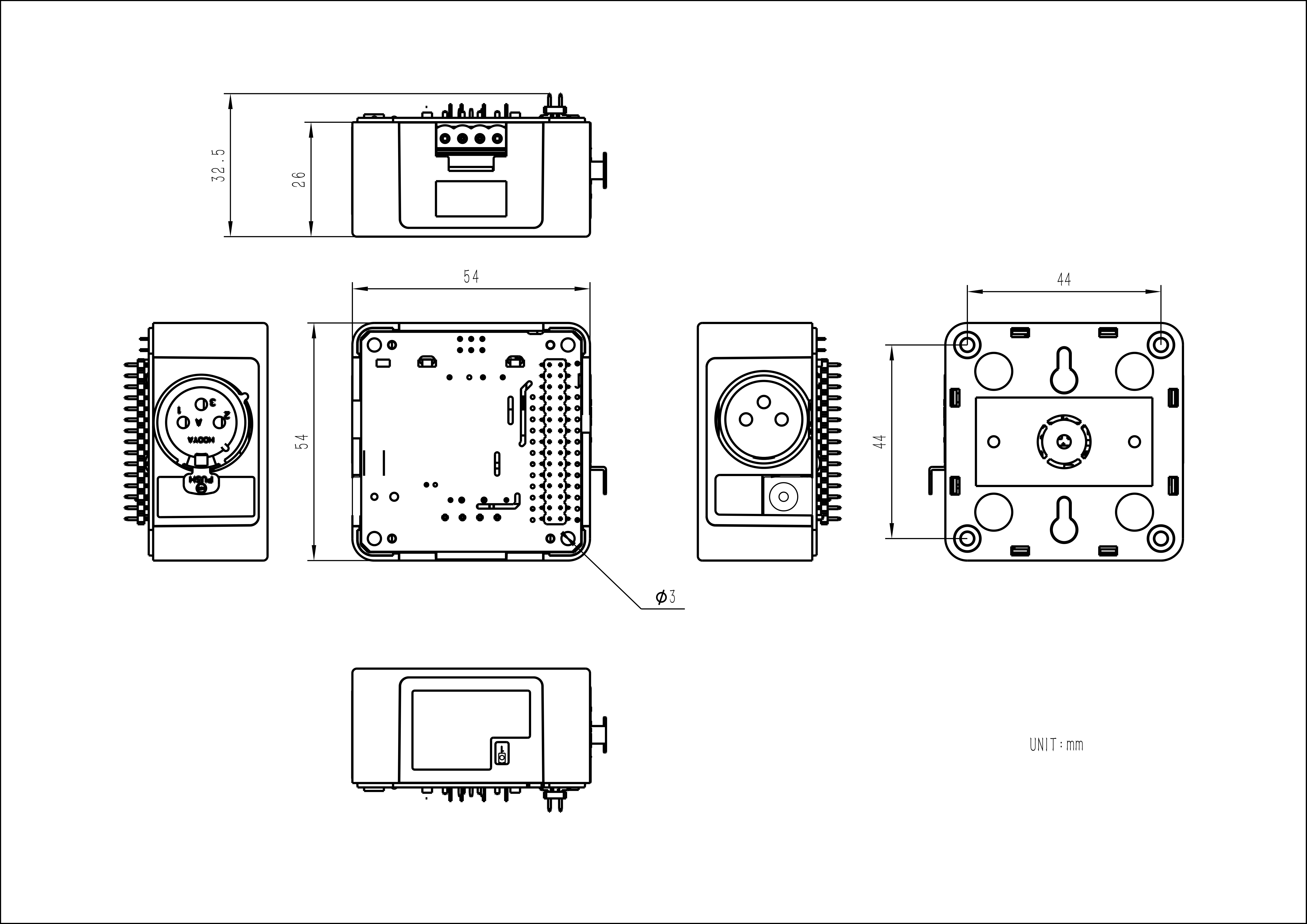
| Product Size | 54.0 x 54.0 x 27.0mm |
| Product Weight | 48.0g |
| Package Size | 147.0 x 90.0 x 40.0mm |
| Gross Weight | 88.2g |
Learn
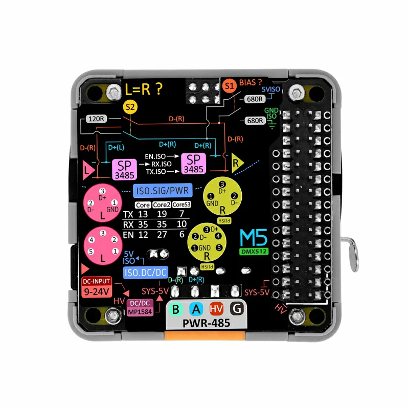
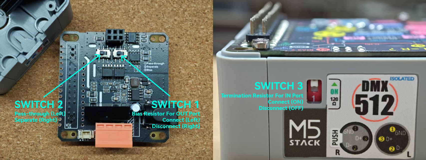
Onboard Switch Function Description
- Switch1: Controls whether the Base DMX output interface is connected to a 680Ω bias resistor. This resistor ensures stable levels on the bus during idle states and improves signal quality.
- Switch2: Controls whether the Base DMX input signal is split (signal input to the host) or bypassed directly to the output interface.
- Switch3: Controls whether the Base DMX input interface is connected to a 120Ω termination resistor. This resistor reduces signal reflection and improves signal quality.
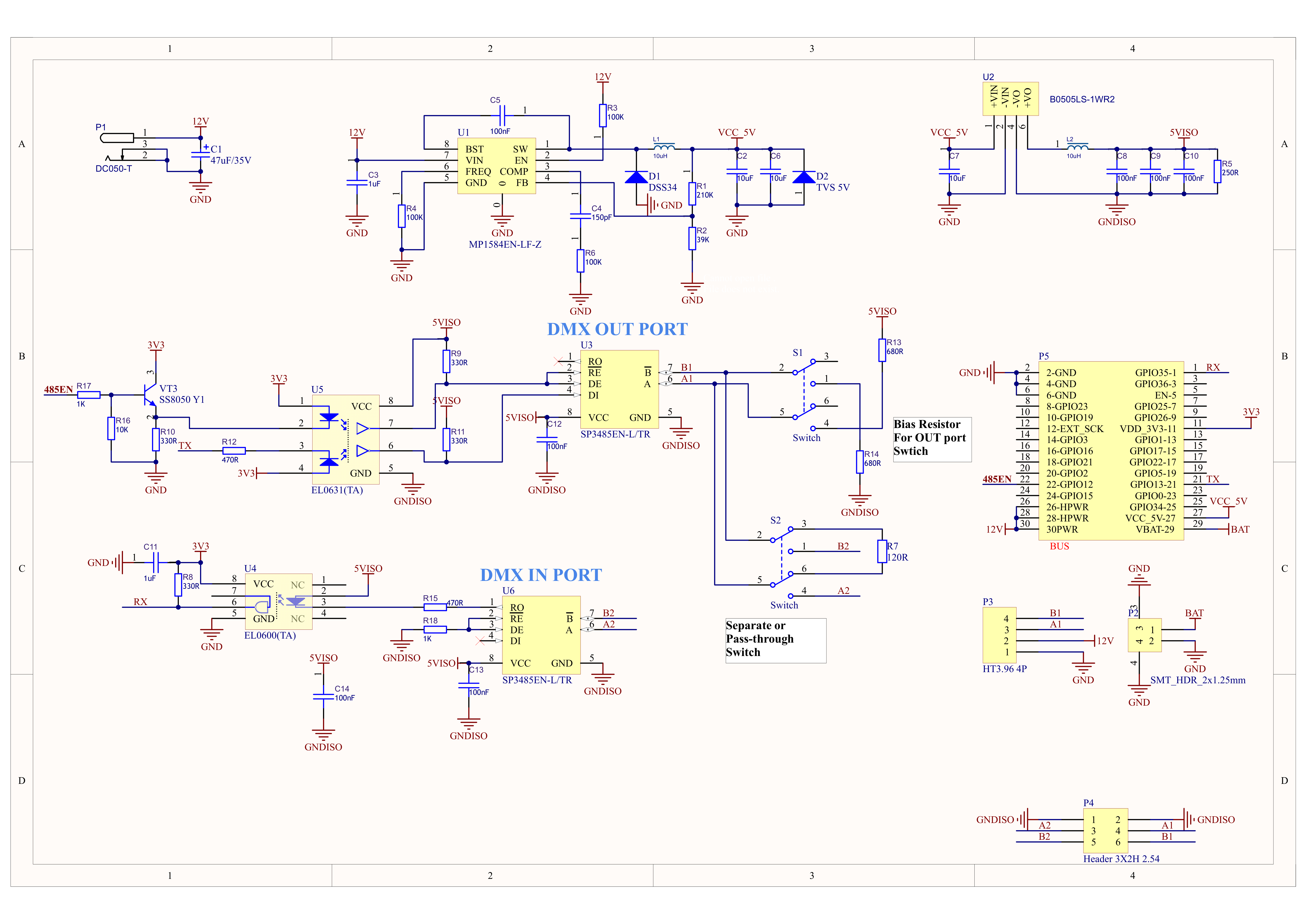
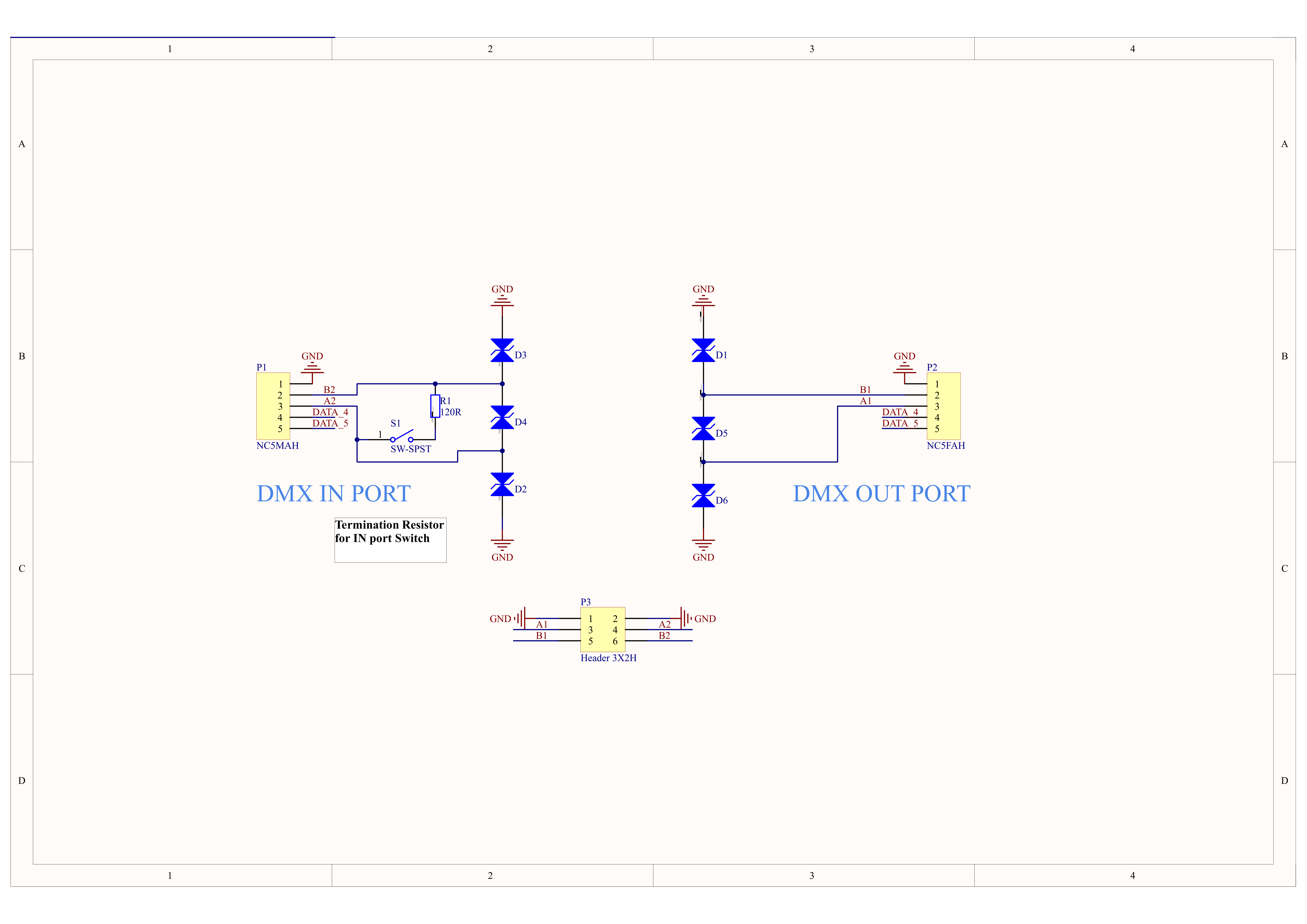
Schematics
PinMap
M5-Bus
| PIN | LEFT | RIGHT | PIN |
|---|---|---|---|
| GND | 1 | 2 | UART_RX |
| GND | 3 | 4 | NC |
| GND | 5 | 6 | NC |
| NC | 7 | 8 | NC |
| NC | 9 | 10 | NC |
| NC | 11 | 12 | 3V3 |
| NC | 13 | 14 | NC |
| NC | 15 | 16 | NC |
| NC | 17 | 18 | NC |
| NC | 19 | 20 | NC |
| RS485_EN | 21 | 22 | UART_TX |
| NC | 23 | 24 | NC |
| HPWR | 25 | 26 | NC |
| HPWR | 27 | 28 | 5V |
| HPWR | 29 | 30 | BAT |
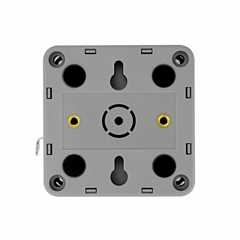
Model Size