VAMeter
SKU:K136
Description
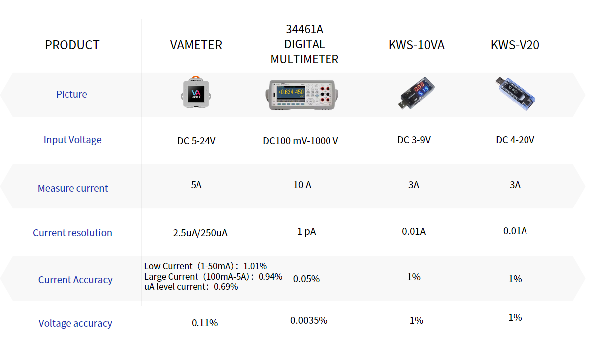
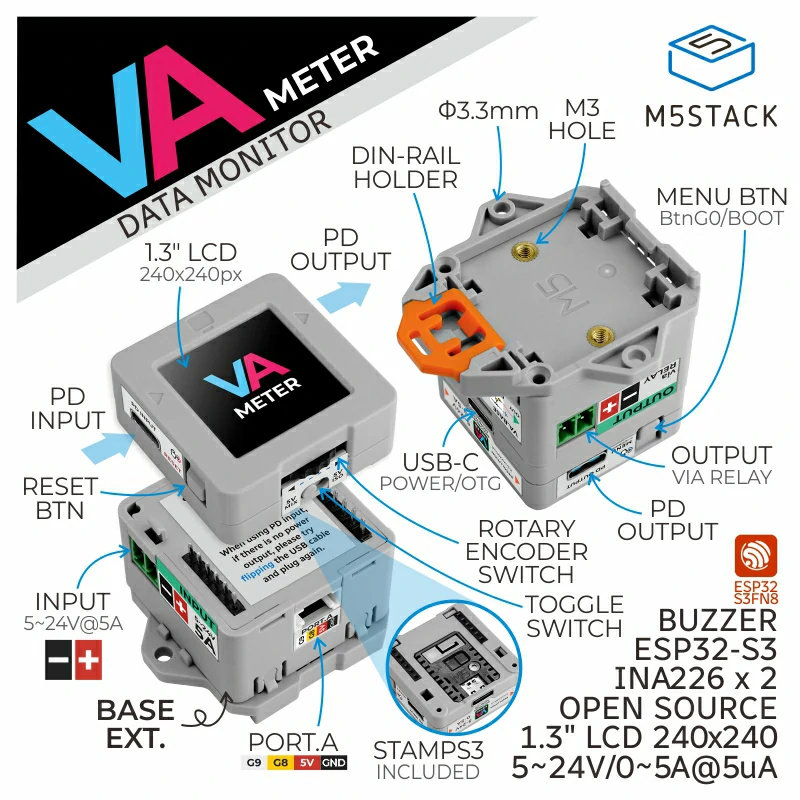
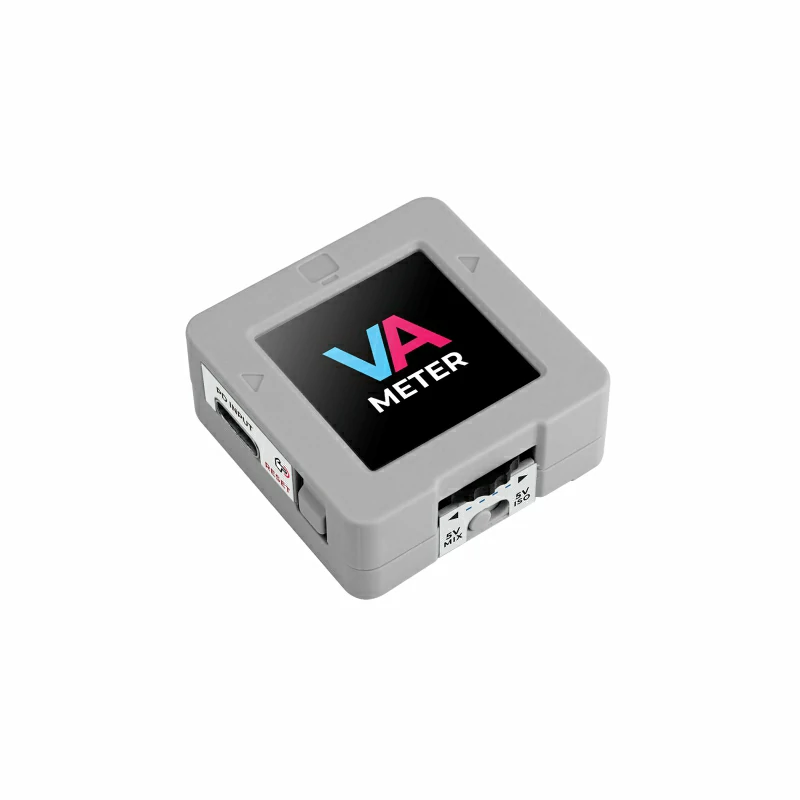
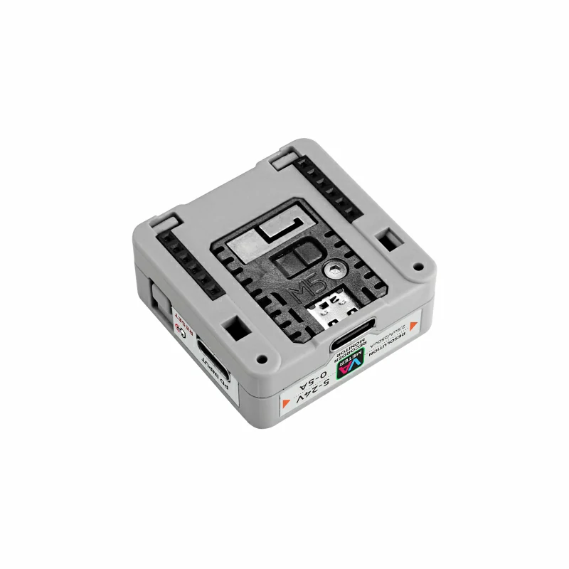
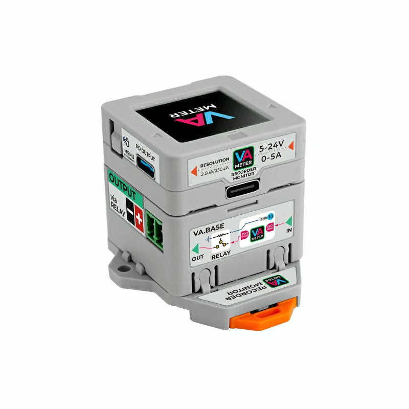
VAMeter is a professional, programmable, high-precision power meter designed for accurate voltage and current measurements. Powered by the Stamp-S3 module, it features Wi-Fi connectivity and two cascaded INA226 current/voltage sensing circuits, delivering current detection resolutions of 2.5 µA and 250 µA. The measurement range supports 0-5 A and 5-24 V (1-24 V in isolation mode).
The device offers flexible power-supply options through the USB-C port or the Base terminal, with built-in power and signal isolation. A slide switch lets users choose between isolated measurements powered via USB and non-isolated measurements powered directly from the test source, meeting various application needs.
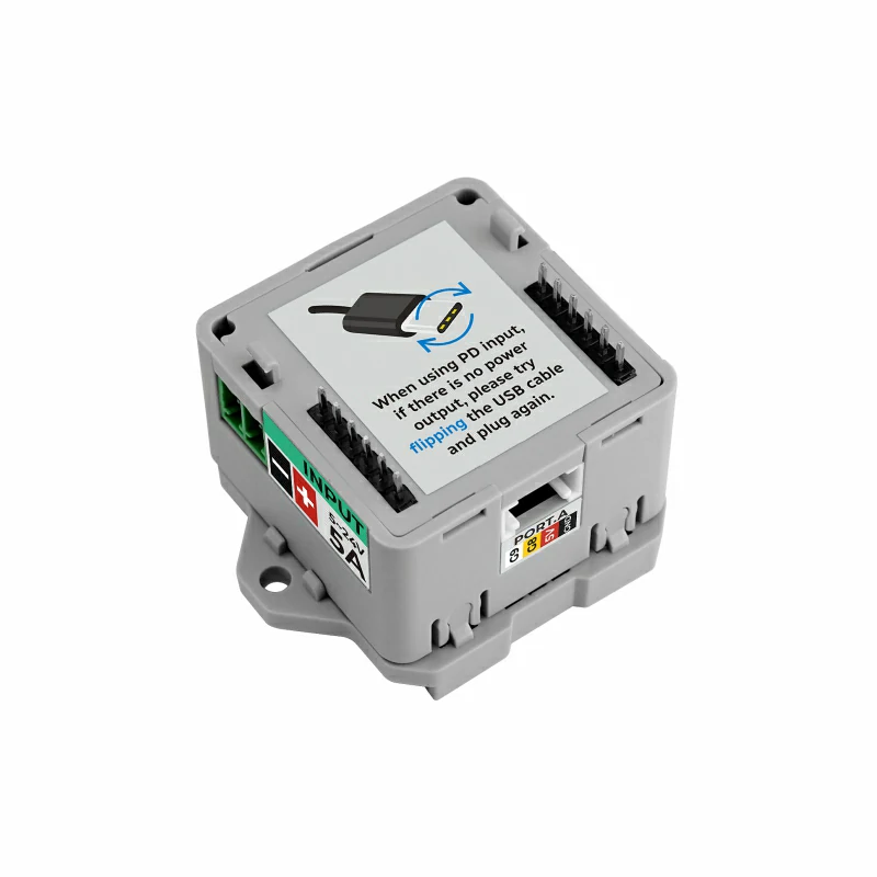
The included expansion BASE provides relay on/off control and a Grove port for secondary development. Additional features include OTA firmware upgrades and USB MSC/OTG support, allowing users to view and edit data and configuration files stored in the main controller’s file system from a PC.
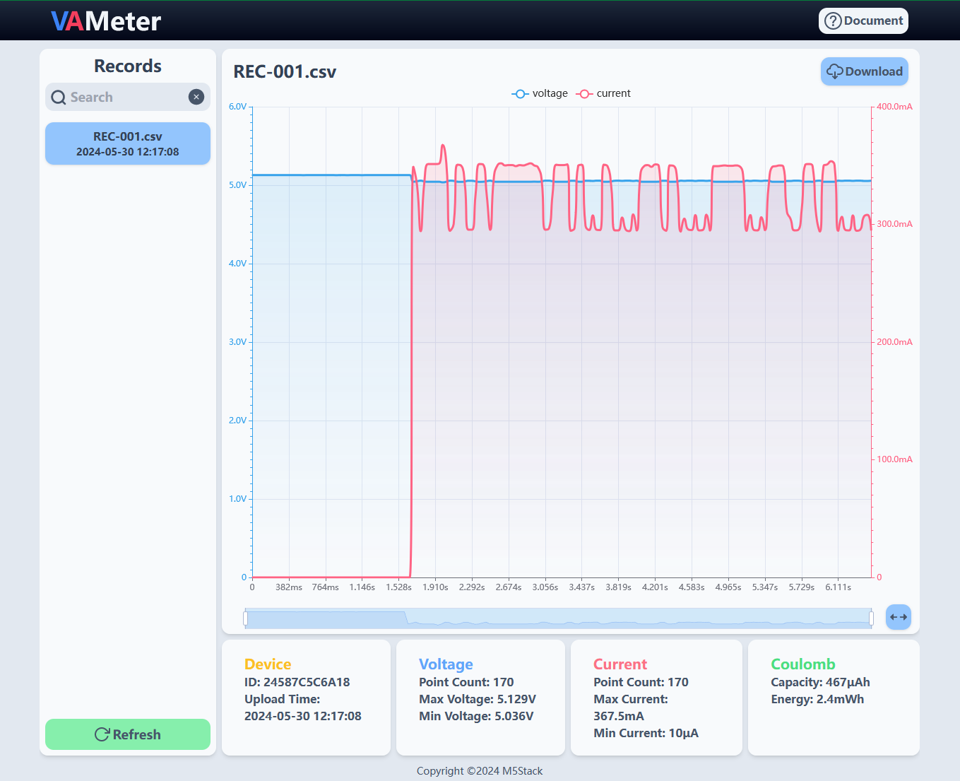
M5Stack also supplies a free online data API for uploading test data to the EZData platform, enabling remote access and visualization and greatly simplifying IoT application development.
VAMeter is a highly practical and developer-friendly instrument, ideal for projects requiring precise current and voltage measurements, as well as for industrial automation, equipment monitoring, smart grid, and related fields.
Tutorial
Features
- High-precision current detection (2.5 µA / 250 µA resolution switching)
- Wide voltage input (5-24 V)
- Cloud data display via EZData
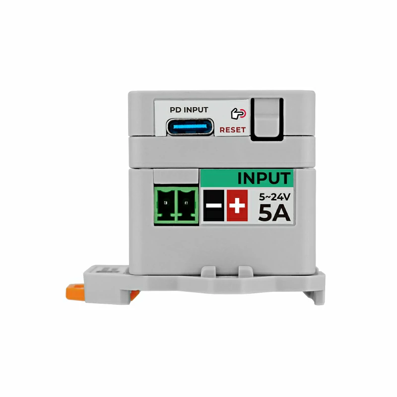
- PD input (no PD trigger built in)
- Multiple power-supply methods (PD INPUT / Stamp-S3 / external terminal block)
- Power and signal isolation
- USB MSC/OTG support
- Open-source hardware & software
- Wireless OTA upgrade
- Development Platform
- Arduino IDE
- ESP-IDF
- PlatformIO
Includes
- 1 x VAMeter
- 1 x VAMeter Base
- 2 x 3.81-2P Terminal Block
- 4 x Hanger (Small)
Applications
- Industrial automation
- Equipment monitoring
- Power testing & analysis
- IoT devices
- Remote monitoring & data acquisition
Specifications
| Specification | Parameter |
|---|---|
| SoC | ESP32-S3FN8 @ Xtensa® 32-bit LX7 dual-core processor, clock frequency 240MHz |
| Power Detection Chip | INA226 |
| Flash | 8MB |
| Wi-Fi | 2.4 GHz Wi-Fi |
| INA226 Communication Address | Dual detection chips INA226: 0x40 / 0x41 |
| Display | 1.3 inch @ 240 × 240 pixels |
| Display Driver | ST7789 |
| PD Input Power | 5-24 V @ 0-5 A |
| Current Resolution | 2.5 µA / 250 µA |
| Current Sampling Err | Small current (1-100 mA): 1.01 % Large current (100 mA-5 A): 0.94 % µA-level current: 0.69 % |
| Voltage Error | Measurement error: 0.11 % |
| Power Consumption | Stamp-S3 USB powered: DC 5 V / 123.5 mA PD INPUT: DC 5 V / 118 mA DC 12 V / 66.8 mA DC 24 V / 26 mA |
| PD OUTPUT Capability | DC 24 V @ 3 A 68 ℃ DC 24 V @ 5 A 92 ℃ |
| User Interface | Rotary encoder switch, Reset button, Boot button, onboard buzzer |
| Relay | DC 5 - 24 V @ 5 A |
| Operating Temp. | 0 - 40 °C |
| Product Size | 51.5 × 48.0 × 40.5 mm |
| Product Weight | 43.4 g |
| Package Size | 160.9 × 93.0 × 31.6 mm |
| Gross Weight | 68.4 g |
Learn
Download Mode
.gif)
M5 EZData Cloud Platform Example
Schematics
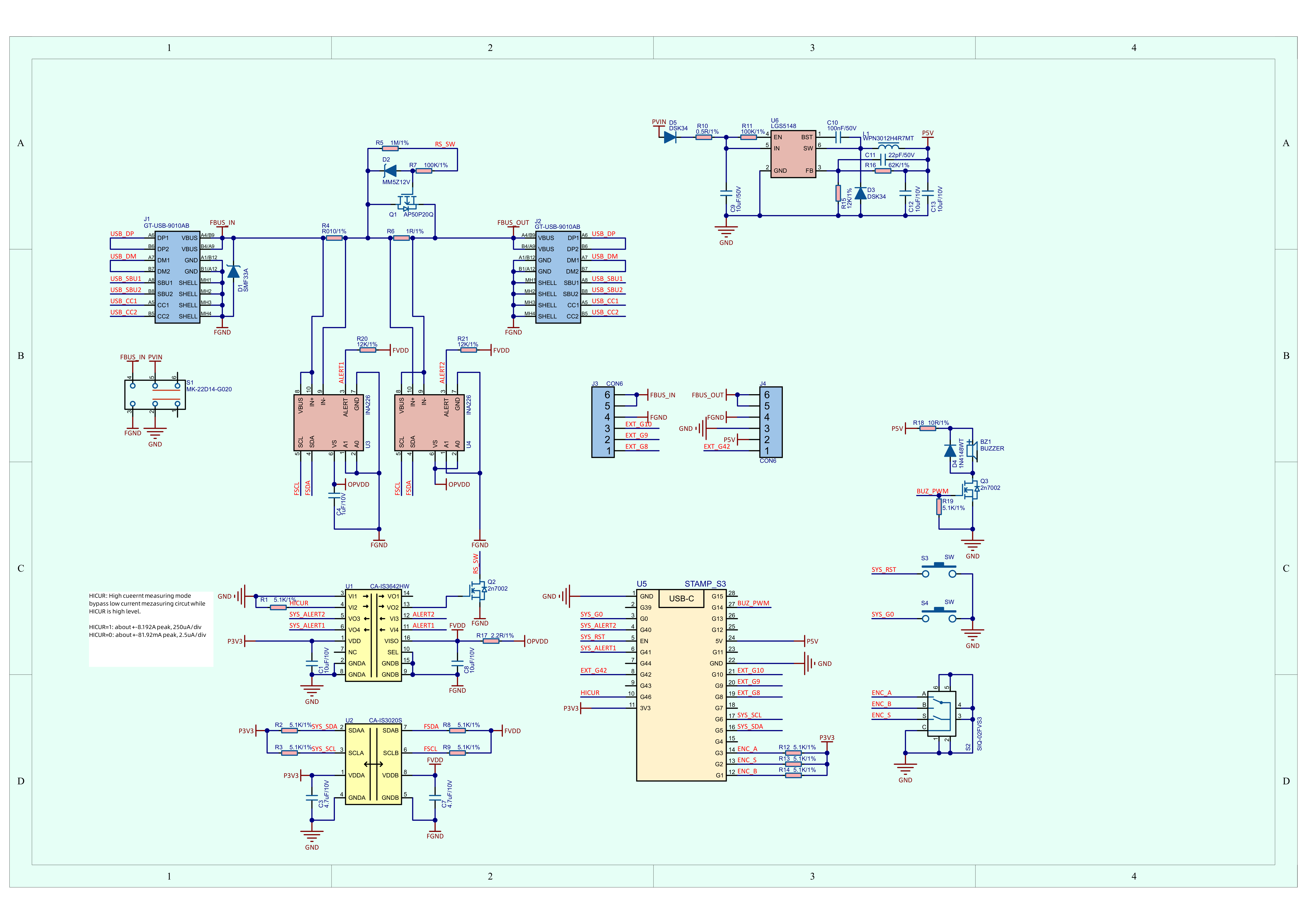
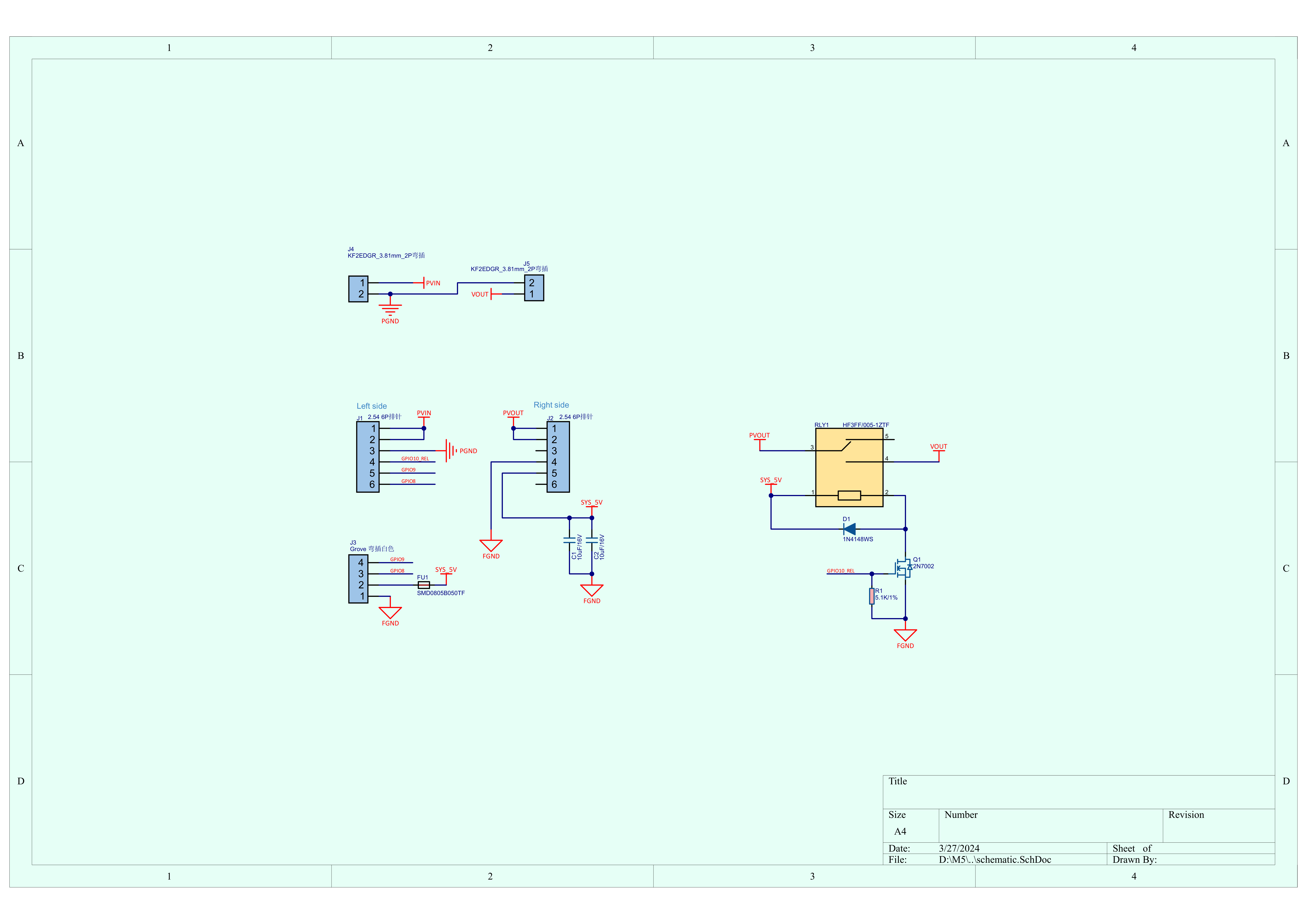
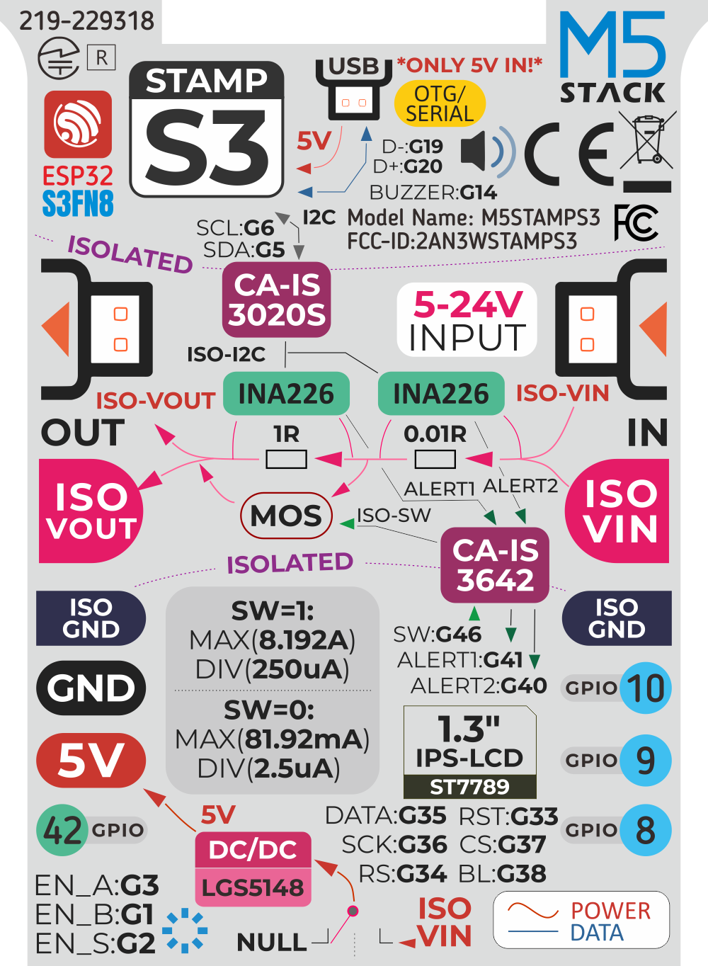
VAMeter Internal Block Diagram
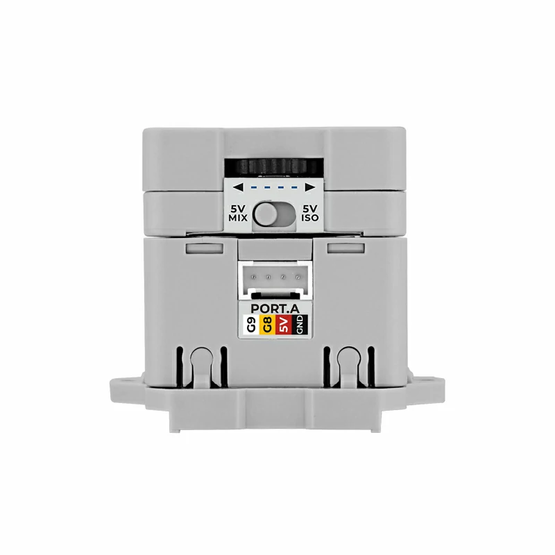
PinMap
VAMeter (INA226 & BUZZER)
| ESP32S3FN8 | G5 | G6 | G41 | G40 | G14 |
|---|---|---|---|---|---|
| INA226 (0x40) | FSDA | FSCL | ALERT1 | ||
| INA226 (0x41) | FSDA | FSCL | ALERT2 | ||
| BUZZER | BUZ_PWM |
VAMeter Expansion Pins
| ESP32S3FN8 | G10 | G9 | G8 | G42 |
|---|---|---|---|---|
| Expansion | EXT_G10 | EXT_G9 | EXT_G8 | EXT_G42 |
VAMeter Base
| ESP32S3FN8 | G10 |
|---|---|
| Relay | G10_REL |
HY2.0-4P
| HY2.0-4P | Black | Red | Yellow | White |
|---|---|---|---|---|
| PORT.CUSTOM | GND | 5V | G8 | G9 |
Model Size
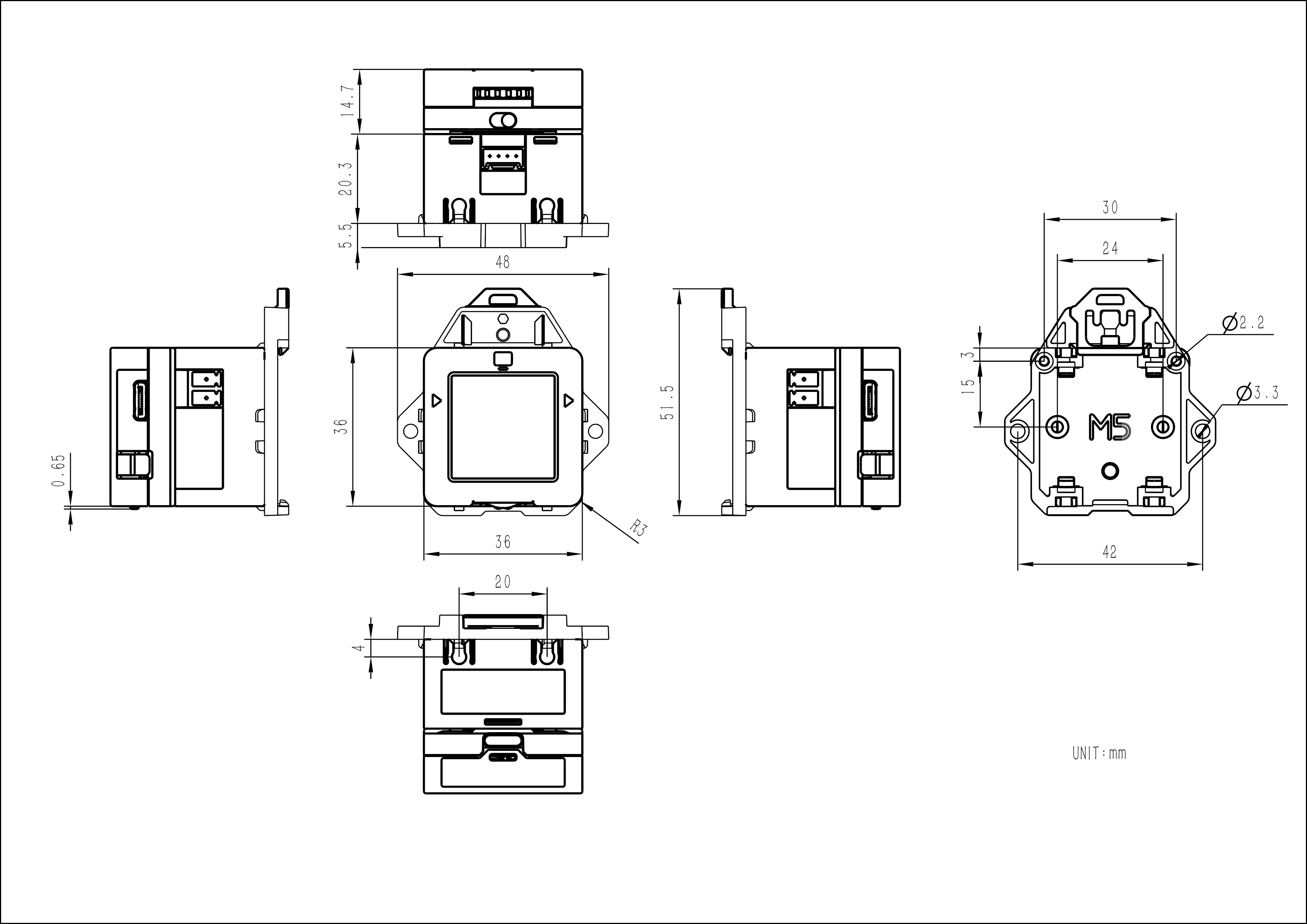
Structure
PCB
Datasheets
Softwares
Quick Start
ESP-IDF
Easyloader
| Easyloader | Download | Note |
|---|---|---|
| VAMeter Firmware Easyloader | download | / |
Other
Video
Product Comparison