

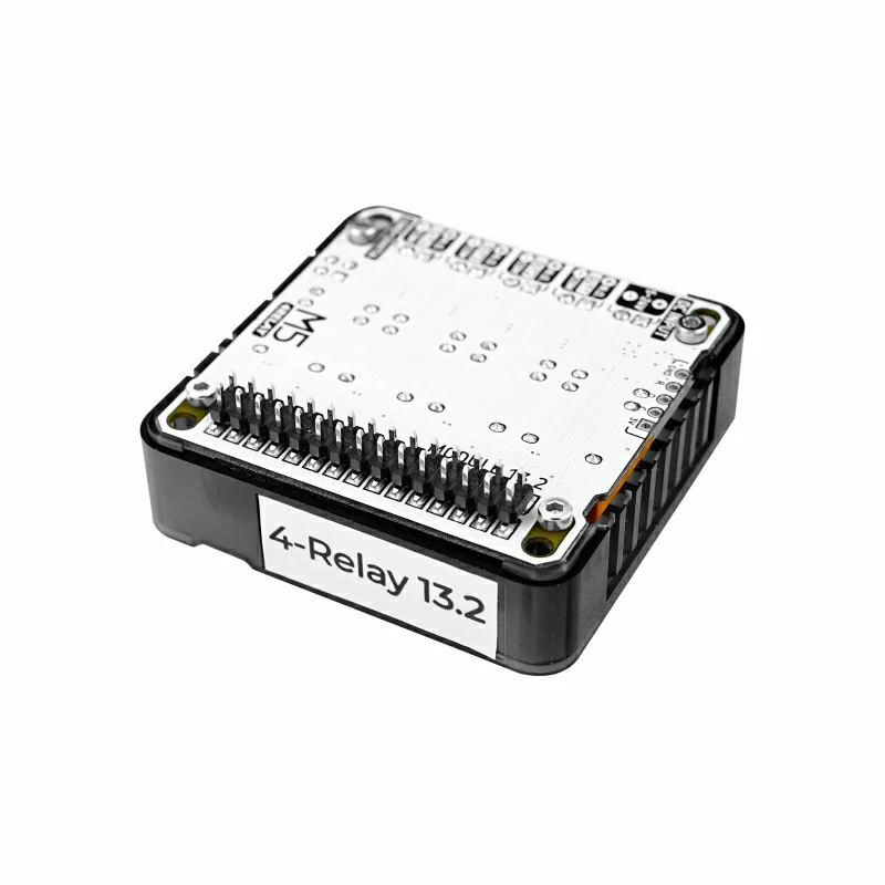
Module13.2 4Relay
SKU:M121
Description
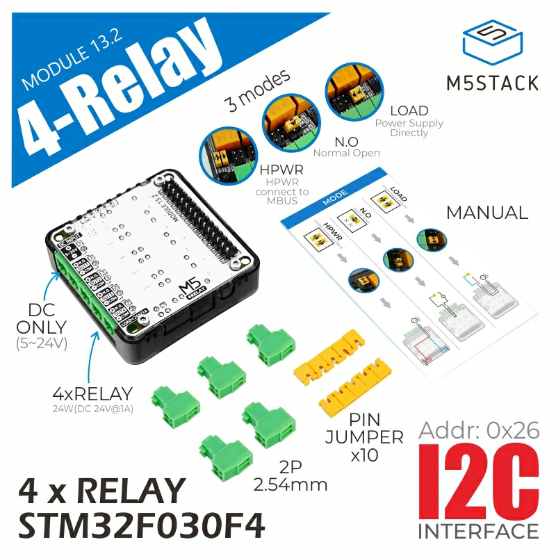
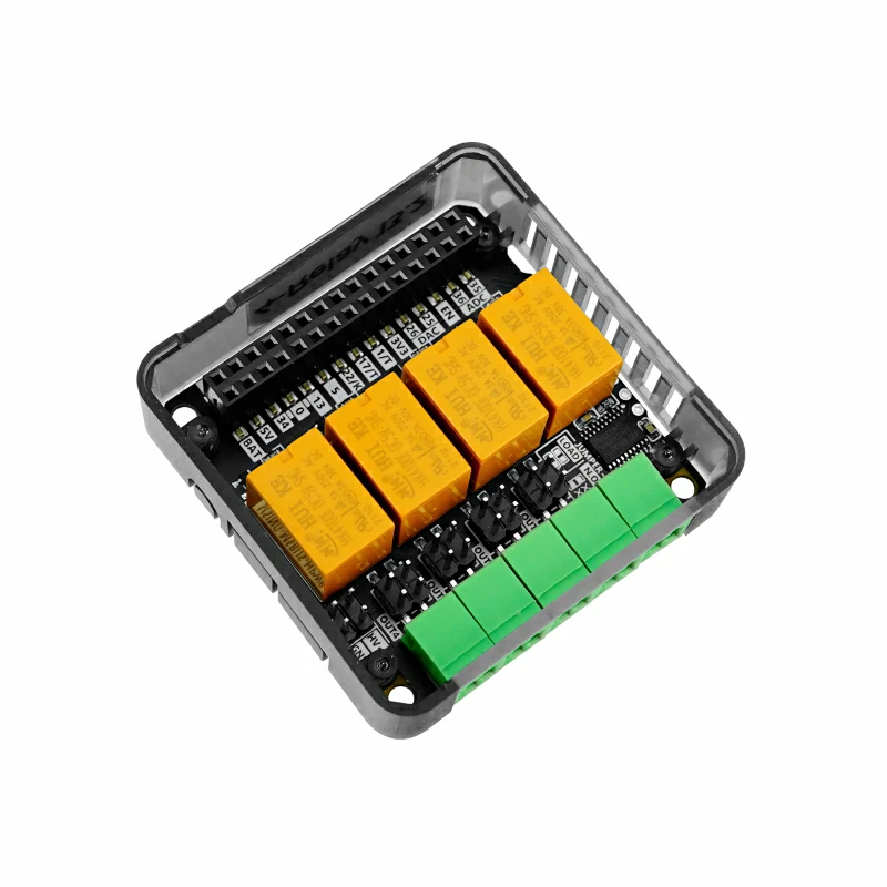
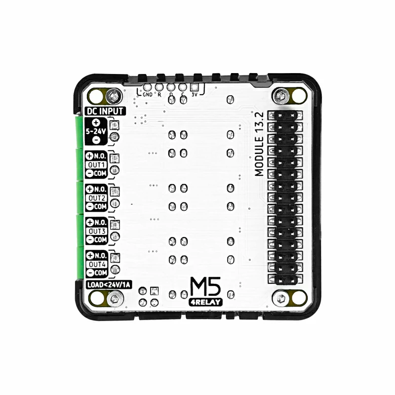
Module13.2 4Relay is a relay module compatible with M5Core/Core2 controllers, featuring 4 mechanical relay control channels (NO, COM). The module uses the I2C communication protocol, effectively saving IO resources. The jumper cap design allows switching between active/passive working modes to meet different circuit requirements. This relay module only supports DC circuit switching, with a maximum load capacity of 24W (DC 24V@1A) per channel, making it suitable for controlling small load circuits.
Features
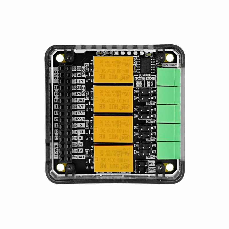
- Embedded STM32F030F4 controller:
- I2C communication interface (addr: 0x26)
- Relays:
- 4 x relay control (COM, NO interface)
- Maximum load capacity 24W (DC 24V@1A)
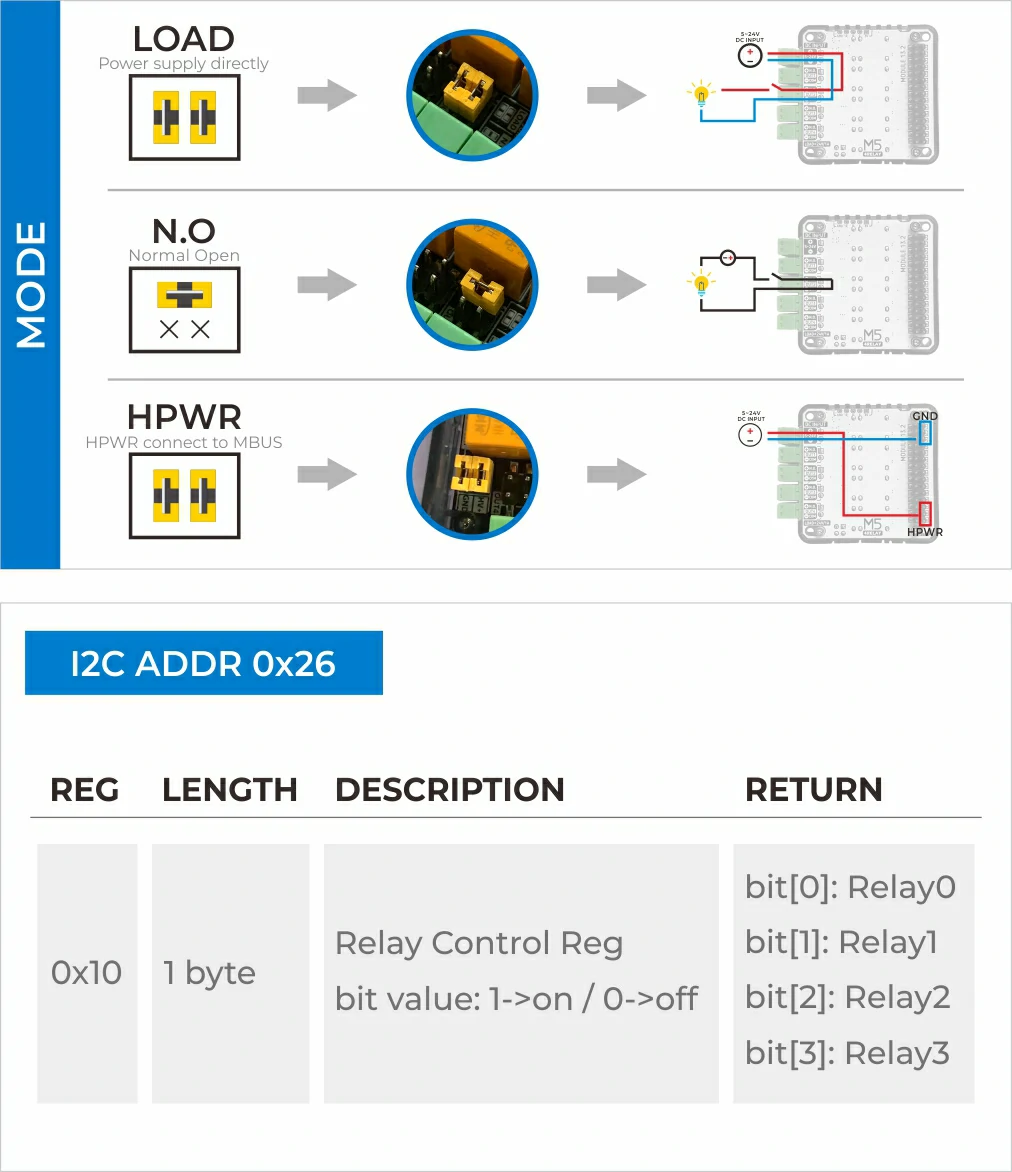
- Supports two working modes (controlled by jumper caps):
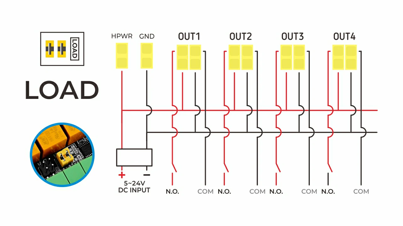
- Active control:
- Power input connected to the relay NO interface, directly powering the load.
- Passive control:
- Power input not connected to the relay interface; user circuit must include power.
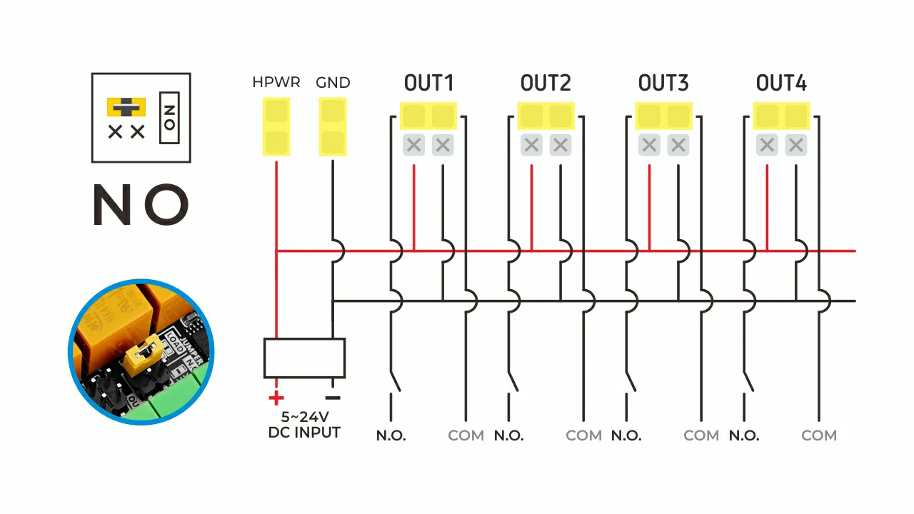
- Active control:
- Power input (DC only):
- DC 5-24V INPUT -> M5 BUS HPWR bus (controlled by jumper caps, when stacking multiple M5 modules, the HPWR bus can power other modules requiring 24V, such as the SERVO2 module)
- Development platforms:
- UIFlow, Arduino
Includes
- 1 x 4Relay Module
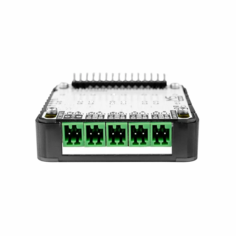
- 5 x 2.54mm-2P terminal blocks (green)
- 10 x jumper caps
- 1 x wiring manual
Applications
- Solenoid valve control
- DC circuit switching
Specifications
| Specification | Parameter |
|---|---|
| Communication Interface | I2C Communication @0x26 |
| Supported working modes | Active control / Passive control |
| Number of relay channels | 4x (COM, NO interface) |
| Power input interface | DC5521 female jack 5.5 x 2.1mm@5-24V (inner positive, outer negative) |
| Load capacity | Maximum load capacity 24W (DC 24V@1A) |
| Relay terminal block spec | 2.54-2P |
| Single relay power consumption | 5V@40mA |
| Coil actuation time | 6ms |
| Coil release time | 4ms |
| Net weight | 37.2g |
| Gross weight | 37.6g |
| Product Size | 54.2 x 54.2 x 13.2mm |
| Package Size | 95 x 65 x 25mm |
Learn
Jumper cap usage instructions
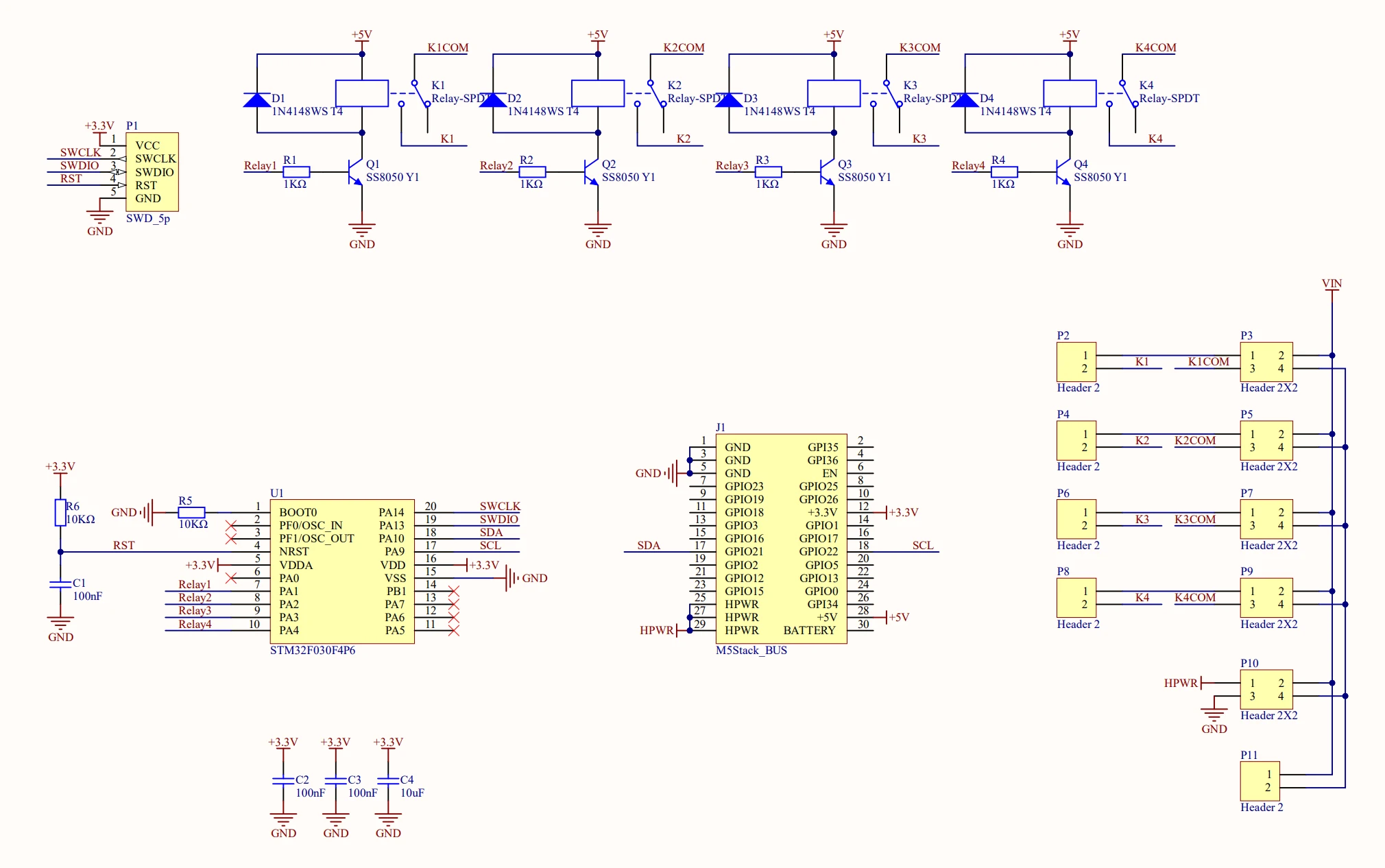
Schematics
PinMap
| M5Core | G22 | G21 | 5V | GND |
|---|---|---|---|---|
| Module13.2 4Relay | SCL | SDA | 5V | GND |
M5-Bus
| PIN | LEFT | RIGHT | PIN |
|---|---|---|---|
| GND | 1 | 2 | |
| GND | 3 | 4 | |
| GND | 5 | 6 | |
| 7 | 8 | ||
| 9 | 10 | ||
| 11 | 12 | 3V3 | |
| 13 | 14 | ||
| 15 | 16 | ||
| SDA | 17 | 18 | SCL |
| 19 | 20 | ||
| 21 | 22 | ||
| 23 | 24 | ||
| HPWR | 25 | 26 | |
| HPWR | 27 | 28 | 5V |
| HPWR | 29 | 30 |