

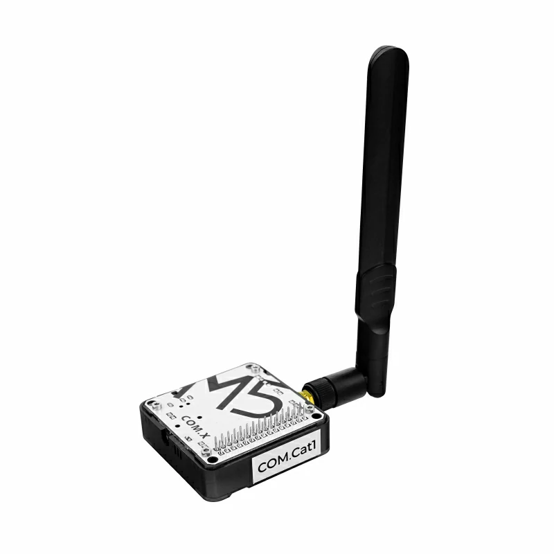
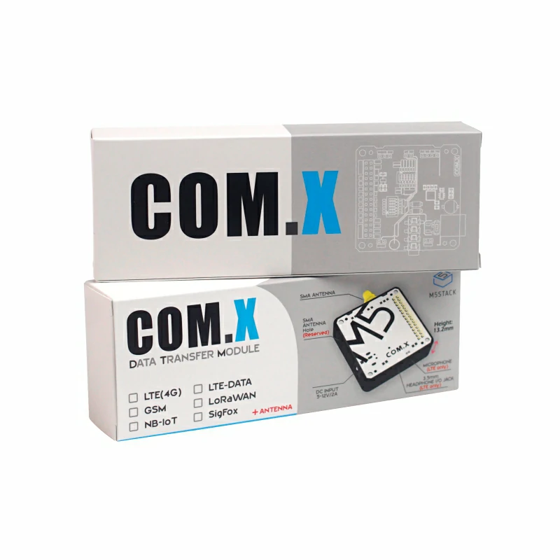
Module COMX Cat1
SKU:M031-H
Description
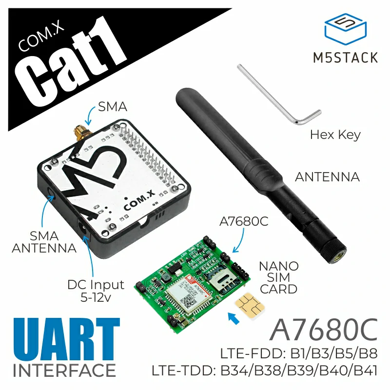
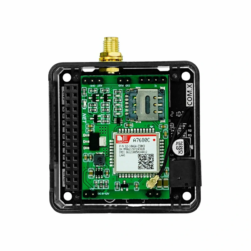
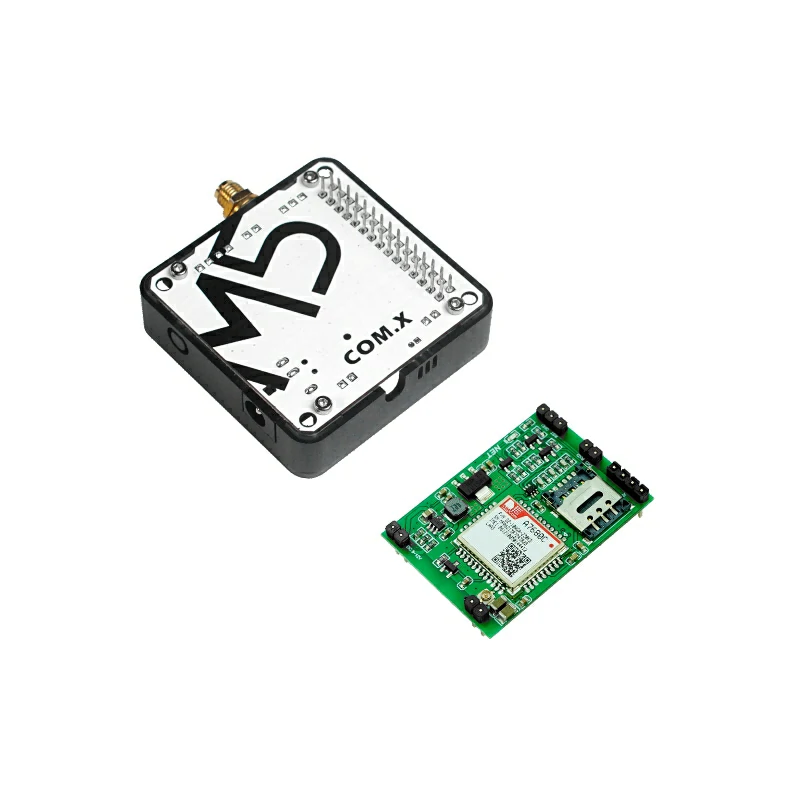
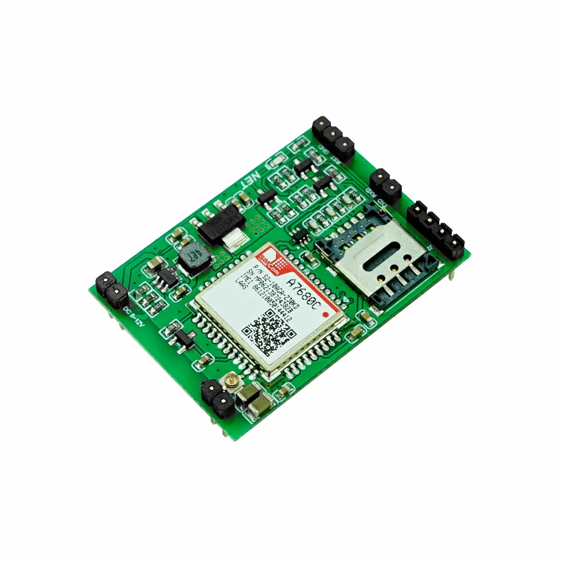
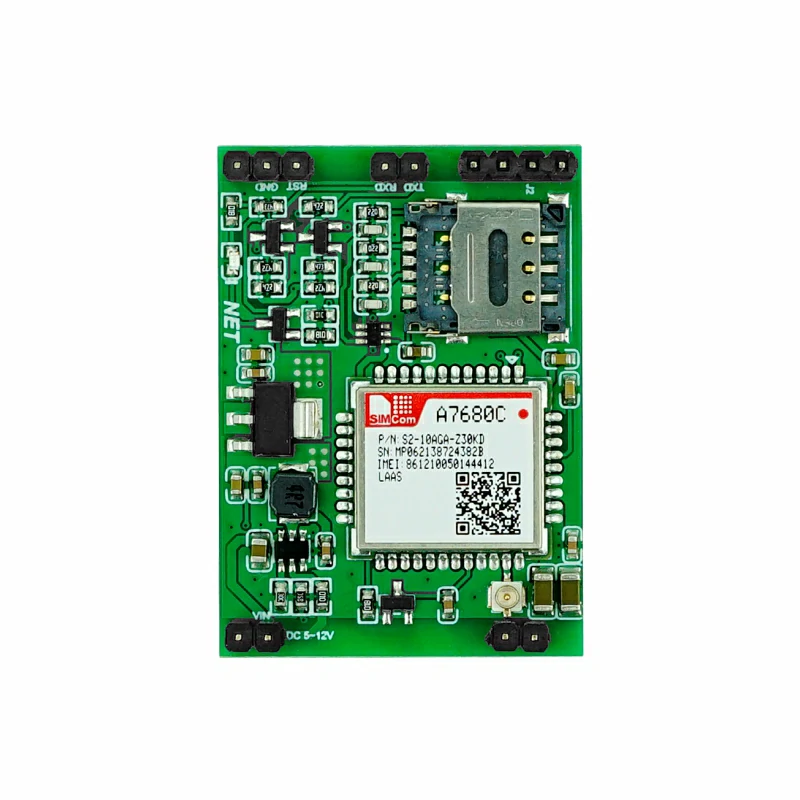
Module COMX Cat1 is an LTE CAT1 data communication module, equipped with the SIM-A7680C module that supports LTE CAT1 frequency bands in China, and supports LTE-TDD/LTE-FDD wireless communication standards. The module integrates an SMA external antenna interface to ensure communication quality and signal stability. It also includes a DC 5 ~ 12V power input interface, providing more power supply options. Compatible with the M5Stack stacking system, it can be stacked with other modules in the series for functional expansion. Compared to NB-IoT, CAT1 offers stronger data transmission capabilities, with a maximum downlink rate of 10Mbps (uplink) / 5Mbps (downlink). This module is ideal for applications requiring data transmission rates, such as remote control and data passthrough.
Features
- SIM-A7680C
- Supports CAT1 frequency bands in China
- LTE CAT1 module, supports LTE-TDD/LTE-FDD wireless communication standards
- Maximum downlink rate of 10Mbps / maximum uplink rate of 5Mbps
- UART interface / AT command control
- Nano SIM card slot
- Module interfaces:
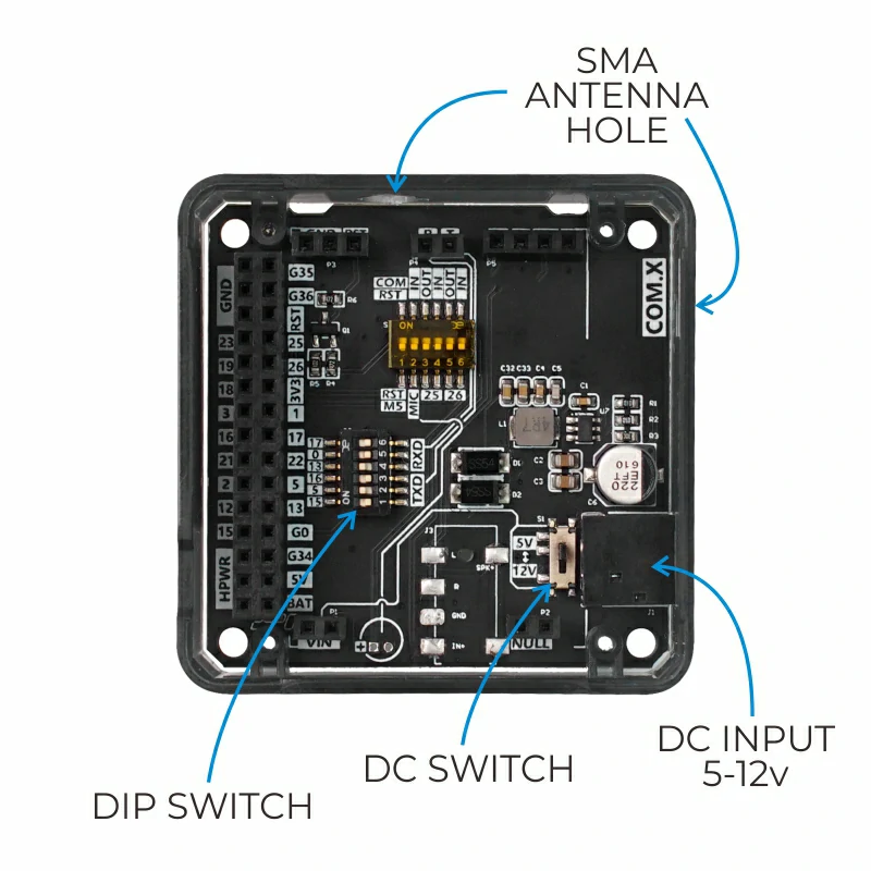
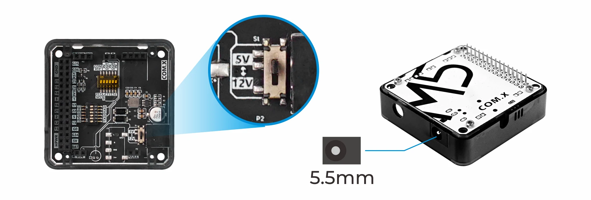
- 1 x DC 5/12V POWER INPUT
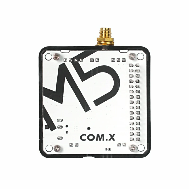
- SMA antenna interface
- Base integrated with a DIP switch for communication pin switching
- 5 x 5cm size, compatible with M5Stack stacking system
- Development platforms:
Includes
- 1 x Module COMX Cat1
- 1 x SMA antenna
Applications
- Remote control / data collection
- Cloud data applications
Certifications
SIM-A7680C Module Certification
- 3C/SRRC/NAL/RoHS/REACH
Specifications
| Specification | Parameters |
|---|---|
| Communication Module | SIM-A7680C |
| Uplink/Downlink Speed | Maximum downlink rate 10Mbps / Maximum uplink rate 5Mbps |
| Supported CAT1 Bands | LTE-TDD: B34/B38/B39/B40/B41 LTE-FDD: B1/B3/B5/B8 |
| Network Protocols | TCP/IP/IPV4/IPV6/MultiPDP/FTP/HTTP/DNS/RNDIS/ECM/PPP/TLS/LBS/TTS/MQTT/WiFi Scan |
| Communication Method | UART 115200bps 8N1 |
| SIM Card Slot | Nano |
| Power Input | M5-Bus(5V) / DC INPUT(5V/12V) |
| Net Weight | 28.6g |
| Gross Weight | 78.0g |
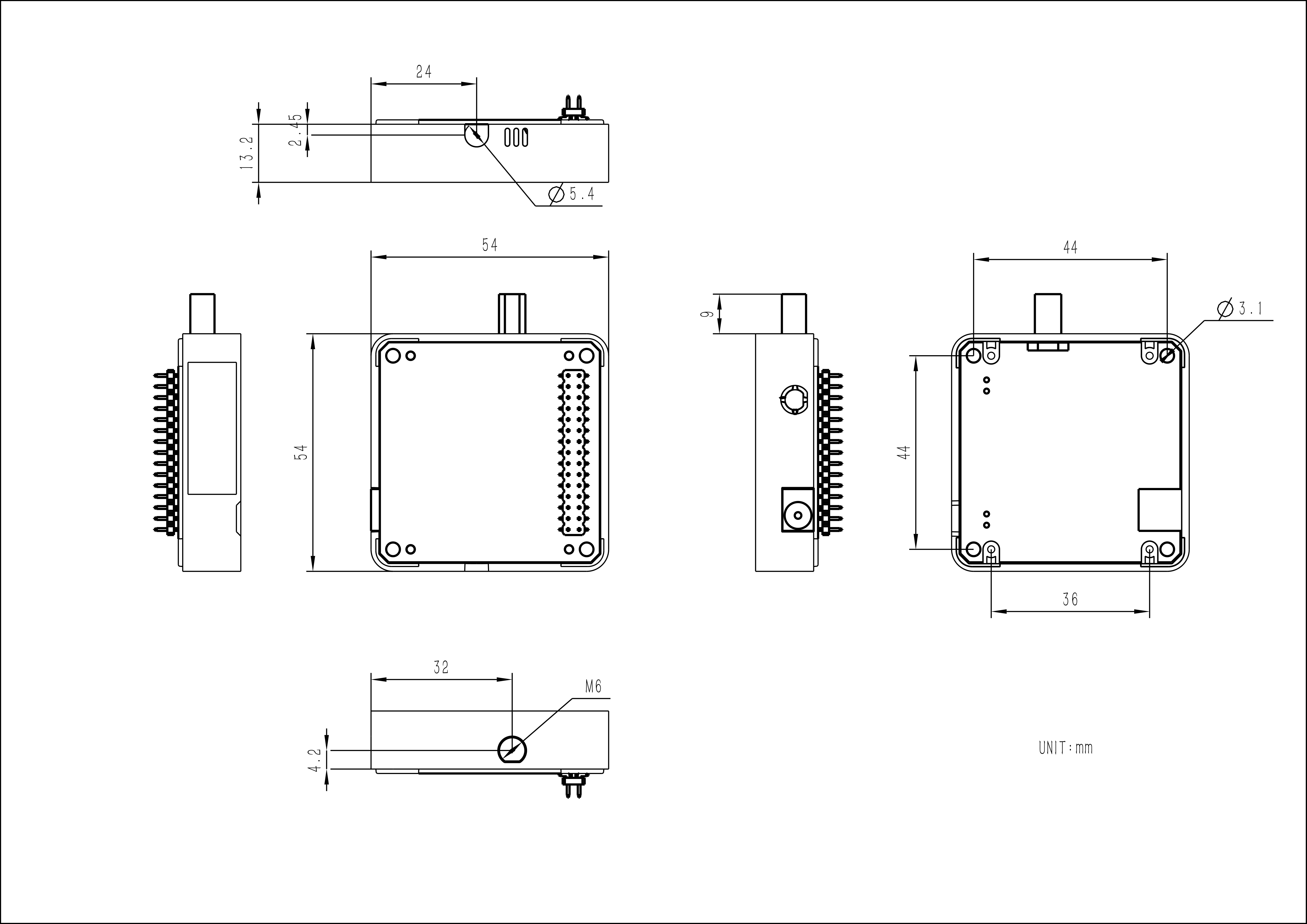
| Product Size | 54.2 x 54.2 x 13.2mm |
| Package Size | 165 x 60 x 36mm |
Learn
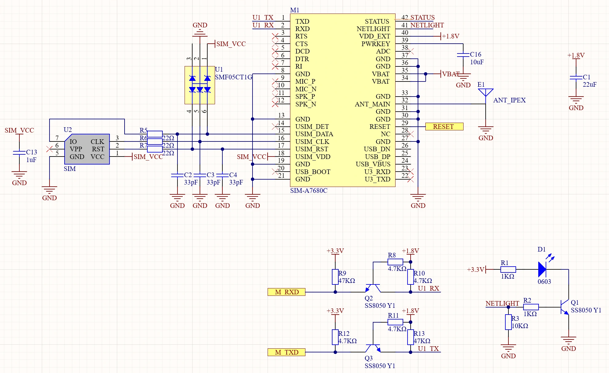
Schematics
Module COMX Baseboard Schematic
PinMap
M5-Bus
SW on the M5-Bus below can be switched via DIP switches to adapt to different main controllers.| PIN | LEFT | RIGHT | PIN |
|---|---|---|---|
| GND | 1 | 2 | |
| GND | 3 | 4 | |
| GND | 5 | 6 | |
| 7 | 8 | ||
| 9 | 10 | ||
| 11 | 12 | 3V3 | |
| 13 | 14 | ||
| TXD (SW) | 15 | 16 | RXD (SW) |
| 17 | 18 | ||
| 19 | 20 | TXD (SW) | |
| 21 | 22 | RXD (SW) | |
| TXD (SW) | 23 | 24 | RXD (SW) |
| 25 | 26 | ||
| 27 | 28 | 5V | |
| 29 | 30 |
Model Size
Datasheets
- Application
- A76XX Series_Audio_Application Note_V1.02.pdf
- A76XX Series_Blue Tooth_Application Note_V1.02.pdf
- A76XX Series_CTBURST_Application Note_V1.00.pdf
- A76XX Series_CTBURST_Application Note_V1.00.pdf
- A76XX Series_FOTA_Application Note_V1.00.pdf
- A76XX Series_FTP(S)_Application Note_V1.02.pdf
- A76XX Series_GNSS_Application Note_V1.02.pdf
- A76XX Series_GNSS_Dynamic_Loading_Instructions_Application Note_V1.00.pdf
- A76XX Series_HTTP(S)_Application Note_V1.02.pdf
- A76XX Series_LBS_Application Note_V1.02.pdf
- A76XX Series_MQTT(S)_Application Note_V1.02.pdf
- A76XX Series_SSL_Application Note_V1.02.pdf
- A76XX Series_Sleep Mode_Application Note_V1.02.pdf
- A76XX Series_TCPIP_Application Note_V1.02.pdf
- A76XX Series_UART_Application Note_V1.02.pdf
- A76XX Series_UIM HOT SWAP_Application Note_V1.02.pdf
- A76XX Series Cloud Platform Protocol Application Document_V1.01.pdf
- AT Command
Softwares
Arduino
- Examples
- Libraries