
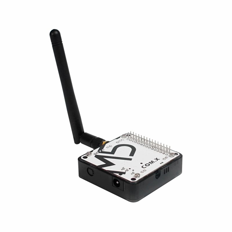
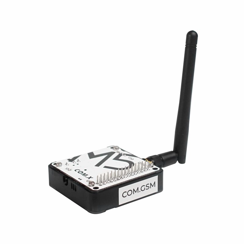
Module COMX GSM
SKU:M031-D
Description
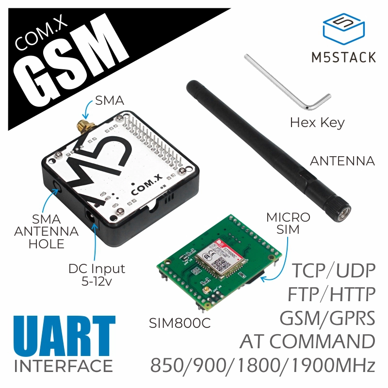
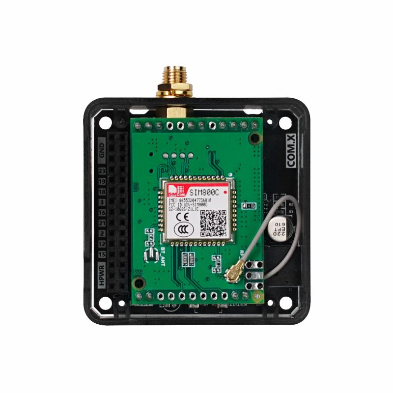
Module COMX GSM is a stackable 2G communication module with a built-in SIM800C communication module, operating at GSM/GPRS frequencies of 850/900/1800/1900MHz, enabling low-power transmission of SMS text and data messages. The module features a DC power input, allowing it to be powered by an external power supply of 5 ~ 12V. For user convenience in configuring pins, a DIP switch is used for pin settings. This module is particularly suitable for IoT industries such as remote meter reading, smart wearables, smart parking, and municipal management, where ultra-low power consumption and compact size are core requirements.
Note
Compatibility
When used with the Fire controller, due to PSRAM pin (G16/G17) conflicts, please switch the module base DIP switch pins to TX(G0/G13), RX(G5/G15).
Features
- Stackable design
- Supports SMS text and data transmission
- Can be powered externally
- AT command control
- SIM card type: MicroSIM
- Status signals: Two LED indicators (power/network status)
- Power supply voltage: 3.4-4.4V
- Typical power consumption in sleep mode: 0.88mA
- External antenna: 2.5dB SMA antenna
- Serial communication: UART 115200bps
- Operating temperature range: -40°C to +85°C
- Frequency bands:
- Quad-band 850/900/1800/1900MHz
- GPRS multi-slot class 12/10
- GPRS mobile station class B
- Data transmission:
- GPRS class 12: Maximum 85.6 kbps (uplink/downlink speed)
- Supports PBCCH (Packet Broadcast Control Channel)
- Coding schemes: CS 1, 2, 3, 4
- Integrated TCP/IP, UDP, HTTP, FTP protocols
- Supports USSD (Unstructured Supplementary Services Data)
Includes
- 1 x Module COMX GSM
- 1 x SMA antenna
Applications
- Smart metering
- Smart parking
- Municipal management
Specifications
| Specification | Parameter |
|---|---|
| Frequency bands | GSM/GPRS 850/900/1800/1900MHz |
| Network protocols | TCP/IP/UDP/FTP/HTTP, etc. |
| Antenna gain | 2.5dB 1880-1900MHz/2320-2370MHz 2575-2635MHz |
| Communication method | UART 115200bps |
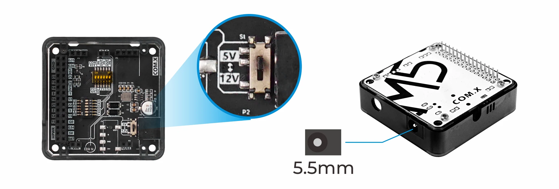
| DC interface specs | 5.5mm |
| Net weight | 40g |
| Gross weight | 75g |
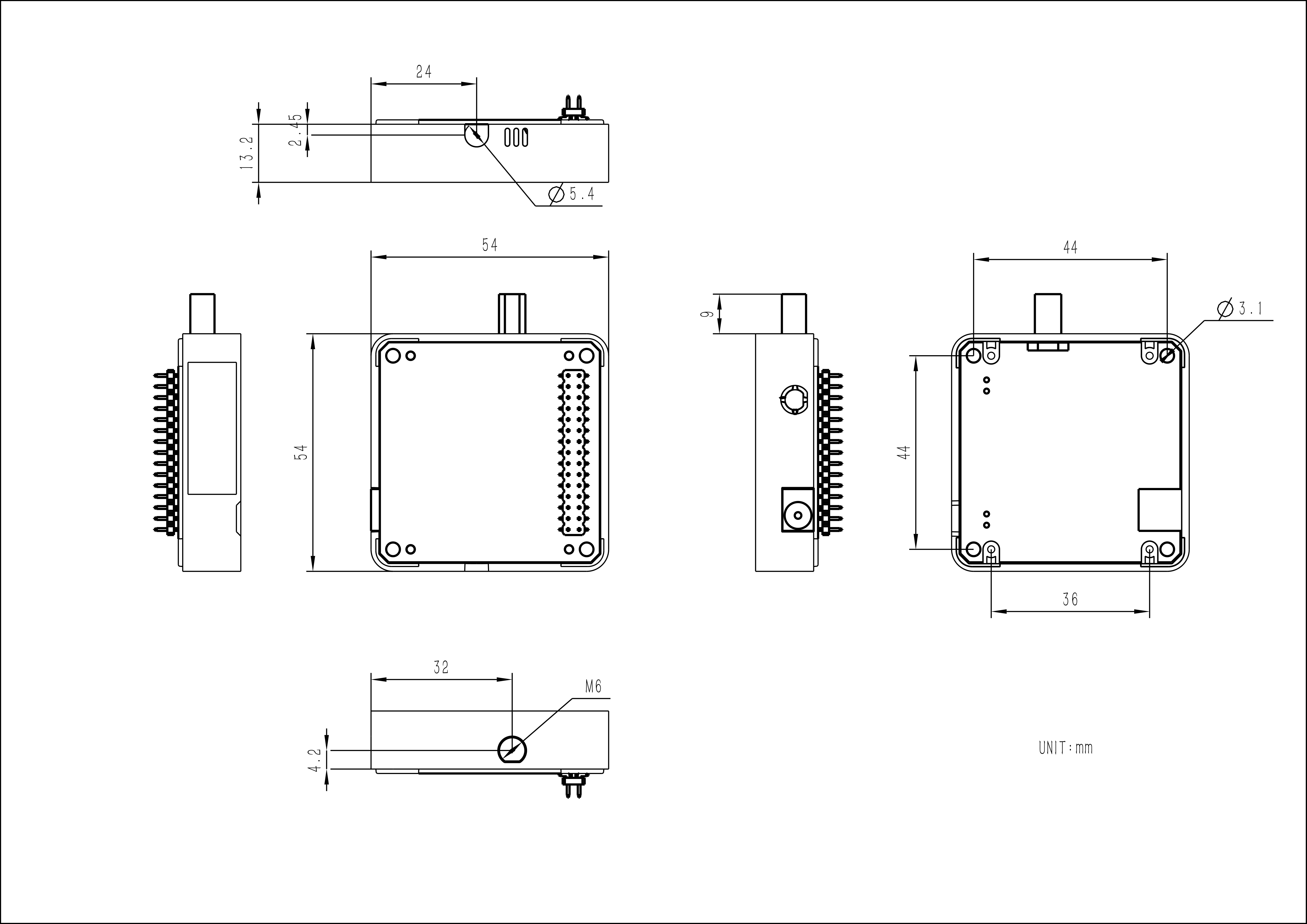
| Module dimensions | 54 x 54 x 13.2mm |
| Package Size | 165 x 60 x 36mm |
Learn
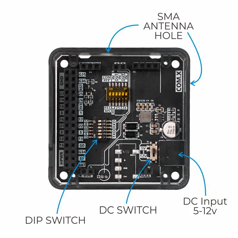
Power supply switching
The module base has a DC power input interface. When using this interface to connect to a power supply, please strictly adhere to the input range (5-12V) to prevent module damage. The internal power DIP switch can adjust the voltage level of the internal terminal VIN to adapt to different modules.
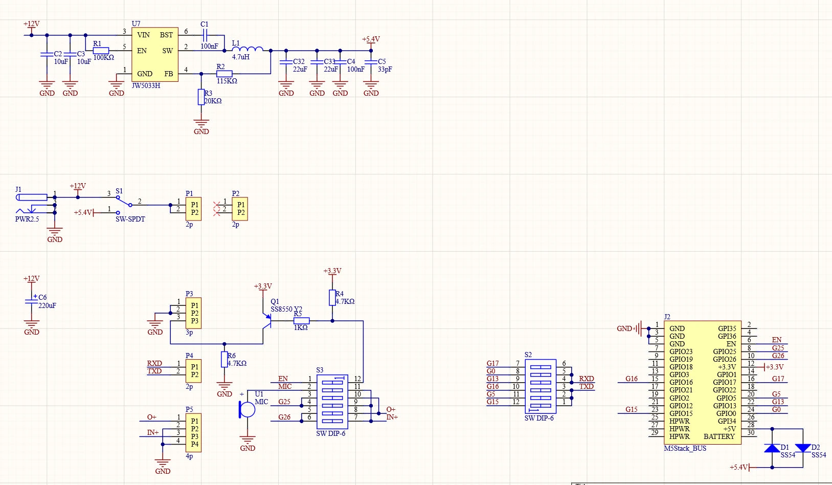
Schematics
Module COMX Module Baseboard Schematic
PinMap
Adjust the DIP switch to the corresponding pins according to different host requirements.
| Controller | CoreS3 | Core2 | Core |
|---|---|---|---|
| RXD | 17/0/7 | 14/0/19 | 17/0/13 |
| TXD | 18/1/13 | 13/33/2 | 16/5/15 |
M5-Bus
Switch
The pins marked
SW on the M5-Bus below can be switched via DIP switches to adapt to different main controllers.| PIN | LEFT | RIGHT | PIN |
|---|---|---|---|
| GND | 1 | 2 | |
| GND | 3 | 4 | |
| GND | 5 | 6 | |
| 7 | 8 | ||
| 9 | 10 | ||
| 11 | 12 | 3V3 | |
| 13 | 14 | ||
| TXD (SW) | 15 | 16 | RXD (SW) |
| 17 | 18 | ||
| 19 | 20 | TXD (SW) | |
| 21 | 22 | RXD (SW) | |
| TXD (SW) | 23 | 24 | RXD (SW) |
| 25 | 26 | ||
| 27 | 28 | 5V | |
| 29 | 30 |
Model Size
Datasheets
Softwares
Arduino
UiFlow1
Protocol
Easyloader
| Easyloader | Download Link | Notes |
|---|---|---|
| Module COMX GSM Example Easyloader with M5Core | download | / |
Video
Page Tools