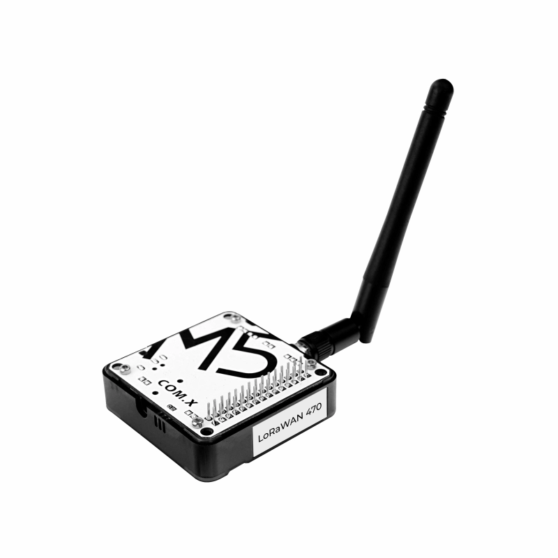
Module COMX LoRaWAN470
SKU:M031-C2

Description
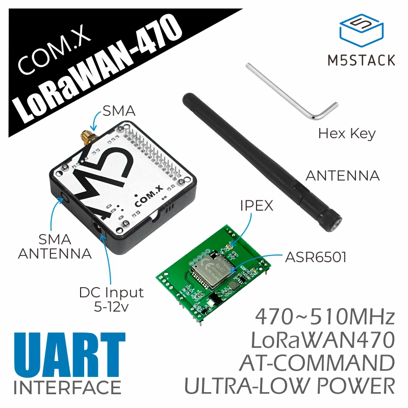
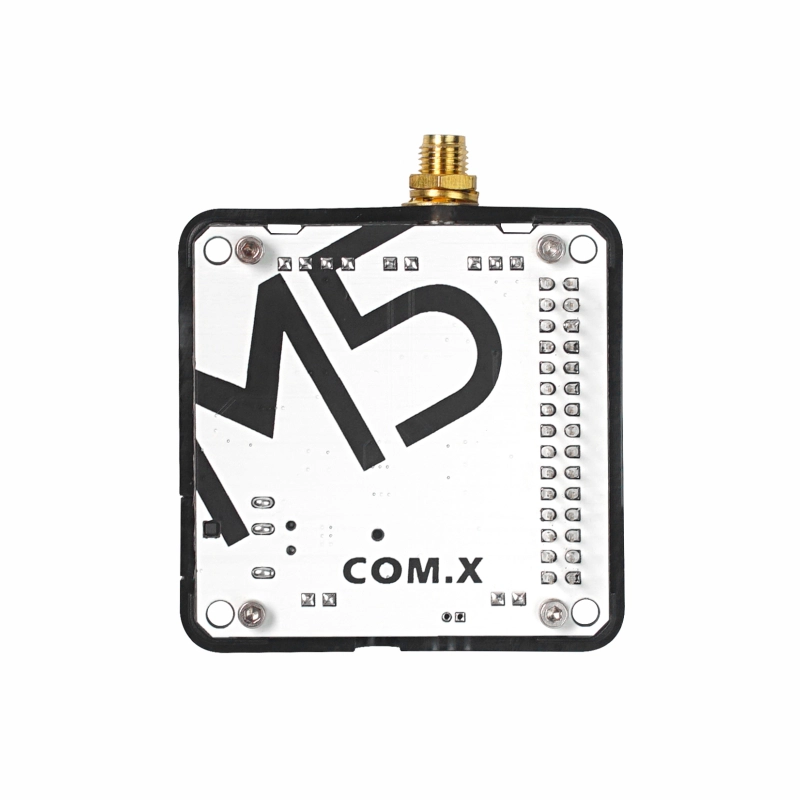
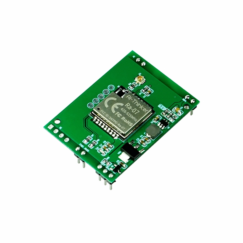
Module COMX LoRaWAN470 is a LoRaWAN communication module launched by M5Stack, suitable for the 470MHz frequency. The module adopts the ASR6501 solution, supporting long-distance communication while featuring ultra-low power consumption and high sensitivity. The module integrates the LoRaWAN protocol stack and uses a serial communication interface (controlled by AT commands). It can be used as a collection node to connect to gateways in large numbers for data collection and management.
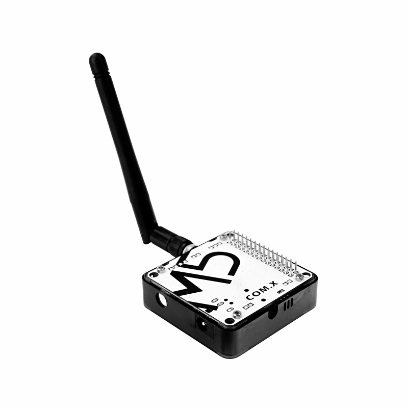
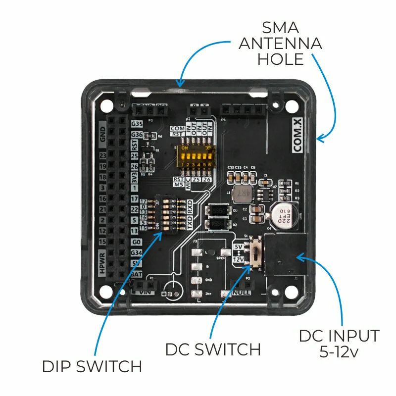
The module provides an external power interface (with a toggle switch to adjust between 5V/12V power input). It is suitable for long-range, low-power IoT communication applications, such as environmental monitoring node deployment.
Note
Compatibility
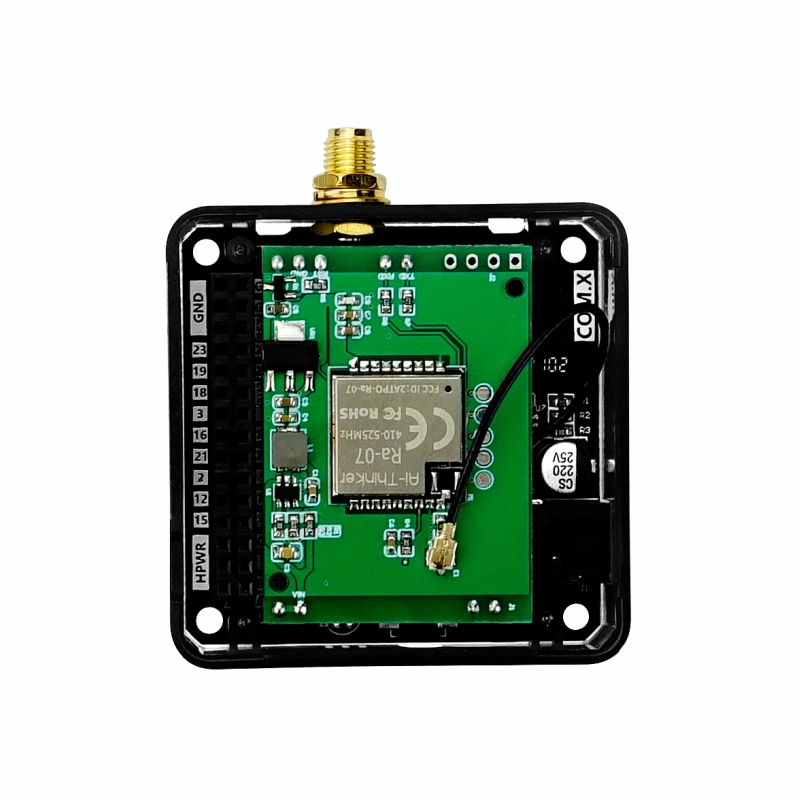
When used with the Fire controller, due to PSRAM pin conflicts (G16/G17), please switch the module base toggle switch pins to TX(G0/G13) and RX(G5/G15).
Features
- ASR6501
- Operating frequency: 470MHz
- SMA antenna
- Command protocol: AT commands
- UART communication interface:
- Baud rate: 115200
- Stop bit: 1
- Data bit: 8
- Parity bit: None
- Terminator: None
Includes
- 1 x Module COMX LoRaWAN470
- 1 x SMA antenna
Applications
- Automatic remote meter reading
- Smart traffic and parking systems
- Remote irrigation and environmental monitoring
Specifications
| Specification | Parameter |
|---|---|
| UART Baud Rate | 115200 |
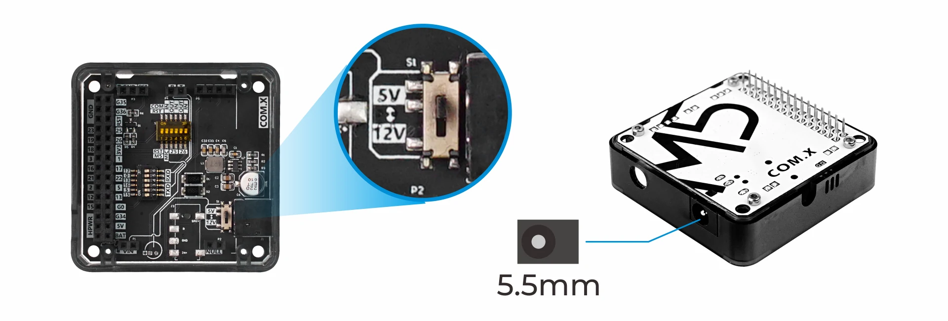
| DC Interface Specification | 5.5mm |
| Net Weight | 35g |
| Gross Weight | 72g |
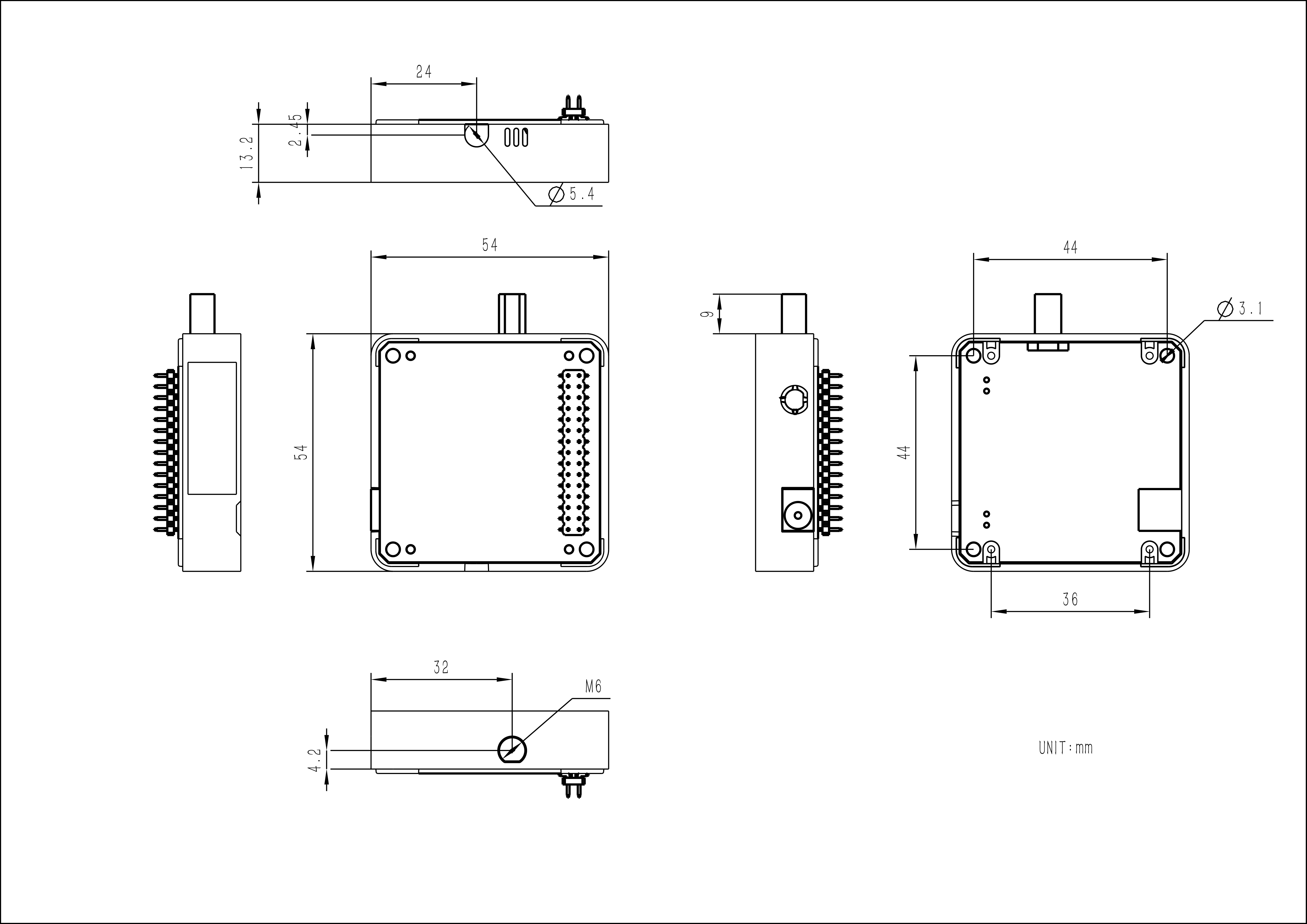
| Product Size | 54.2 x 54.2 x 13.2mm |
| Package Size | 165 x 60 x 36mm |
Learn
CN470 Supported Countries and Regions
China

Power Supply Switching
The module base has a DC power input interface. When using this interface to connect to a power supply, please strictly adhere to the input range (5-12V) to prevent module damage. The internal power toggle switch can adjust the voltage level of the internal VIN terminal to adapt to different modules.
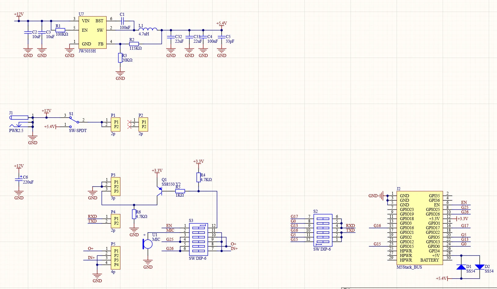
Schematics
Module COMX Baseboard Schematic
PinMap
Adjust the toggle switch to the corresponding pins based on different host requirements.
| Controller | CoreS3 | Core2 | Core |
|---|---|---|---|
| RXD | 17/0/7 | 14/0/19 | 17/0/13 |
| TXD | 18/1/13 | 13/33/2 | 16/5/15 |
M5-Bus
Switch
The pins marked
SW on the M5-Bus below can be switched via DIP switches to adapt to different main controllers.| PIN | LEFT | RIGHT | PIN |
|---|---|---|---|
| GND | 1 | 2 | |
| GND | 3 | 4 | |
| GND | 5 | 6 | |
| 7 | 8 | ||
| 9 | 10 | ||
| 11 | 12 | 3V3 | |
| 13 | 14 | ||
| TXD (SW) | 15 | 16 | RXD (SW) |
| 17 | 18 | ||
| 19 | 20 | TXD (SW) | |
| 21 | 22 | RXD (SW) | |
| TXD (SW) | 23 | 24 | RXD (SW) |
| 25 | 26 | ||
| 27 | 28 | 5V | |
| 29 | 30 |
Model Size