
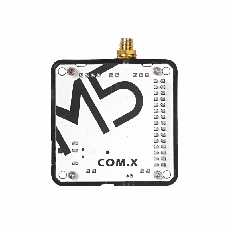
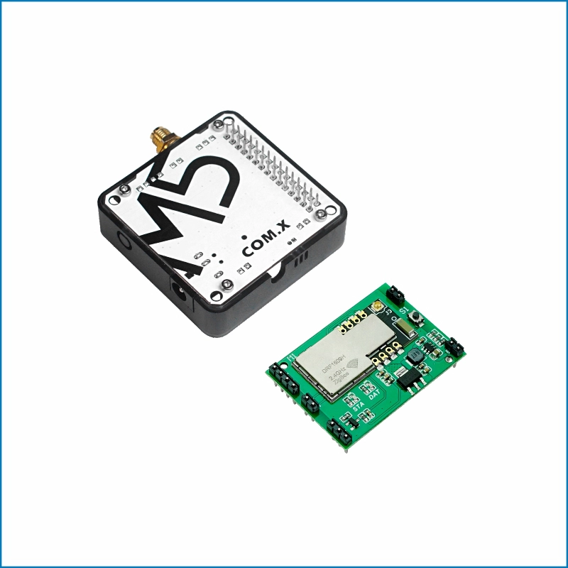
Module COMX Zigbee
SKU:M031-Z
Description
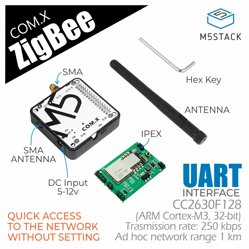
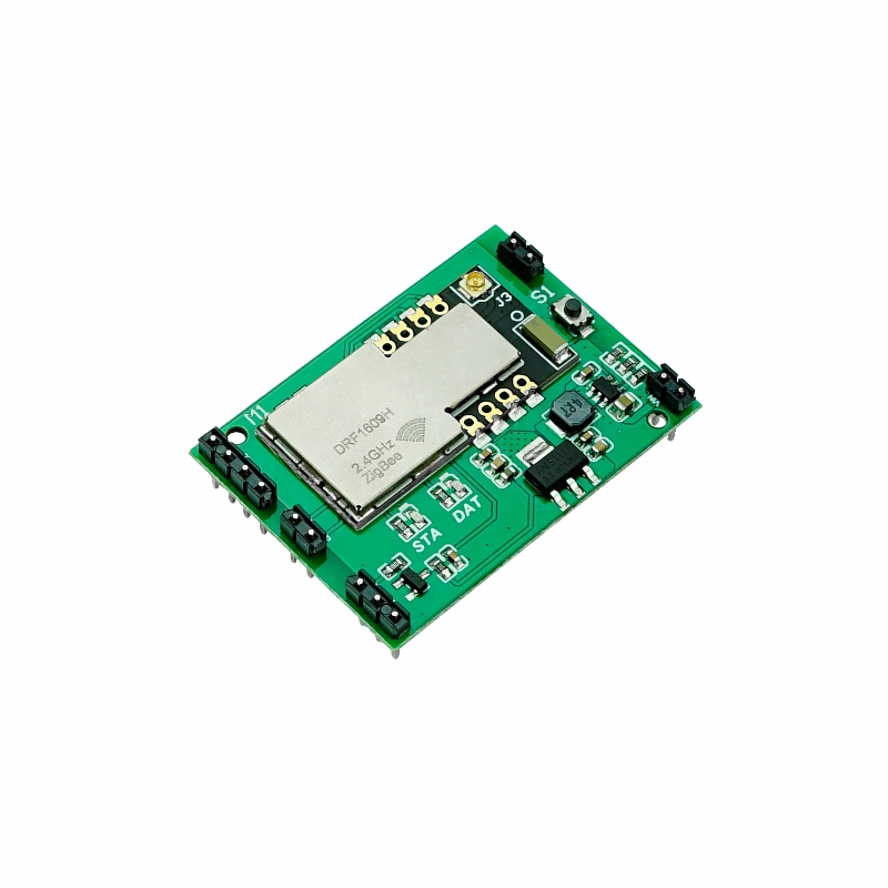
Module COMX Zigbee is a Zigbee self-organizing network communication module launched by M5Stack. The module adopts the CC2630F128 solution, integrates the Zigbee protocol stack internally, and provides an open serial communication interface. With an integrated external antenna, the stable communication distance of a single node can reach up to 1km, with a 200-level router depth. Through the MESH networking method, it can extend your IoT applications over a wide range, featuring ultra-low power consumption and high sensitivity. The Zigbee network can support hundreds of nodes and has enhanced security features, providing a complete and interoperable IoT solution for home and building automation.
Note
Compatibility
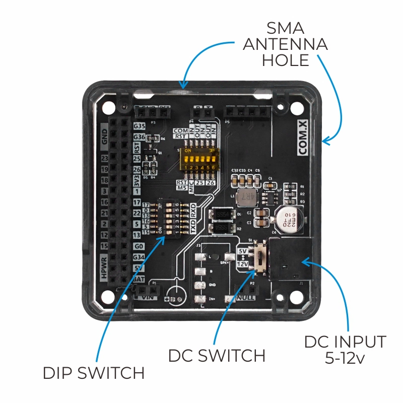
When used with the Fire main control, due to PSRAM pin conflicts (G16/G17), please switch the module base DIP switch pins to TX(G0/G13), RX(G5/G15) during use.
Features
- CC2630F128
- Quick network access without setup
- Initialize the coordinator and configure the router preset, enabling automatic network access by pressing the button three times.
- Serial communication
- Low power consumption (module operating current: 25mA, sleep 5uA)
- Dynamic routing maintenance, supports 200-level routing depth
- Transmission speed 250Kbps
- Node communication distance 1km
- UART transparent transmission/broadcast/P2P
Includes
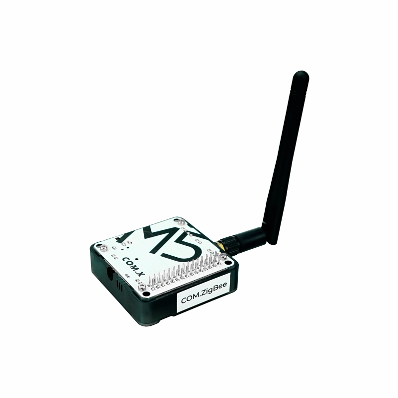
- 1 x Module COMX Zigbee
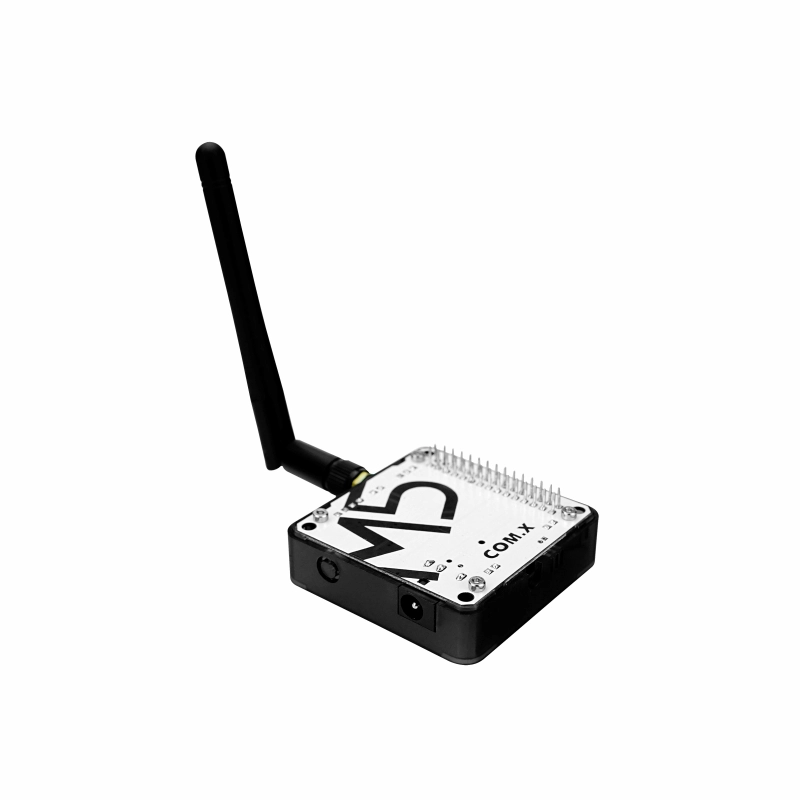
- 1 x SMA antenna
Applications
- Smart home
- IoT collection nodes
- Building automation
Specifications
| Specification | Parameter |
|---|---|
| CC2630F128 | ARM Cortex-M3 32bit |
| Communication Mode | UART 38400bps 8N1 (default) |
| Communication Distance | 1km (Open Area) |
| Operating Frequency | 2.4GHz (2405MHz-2480MHz, step 5MHz) |
| DC Interface Specification | 5.5mm |
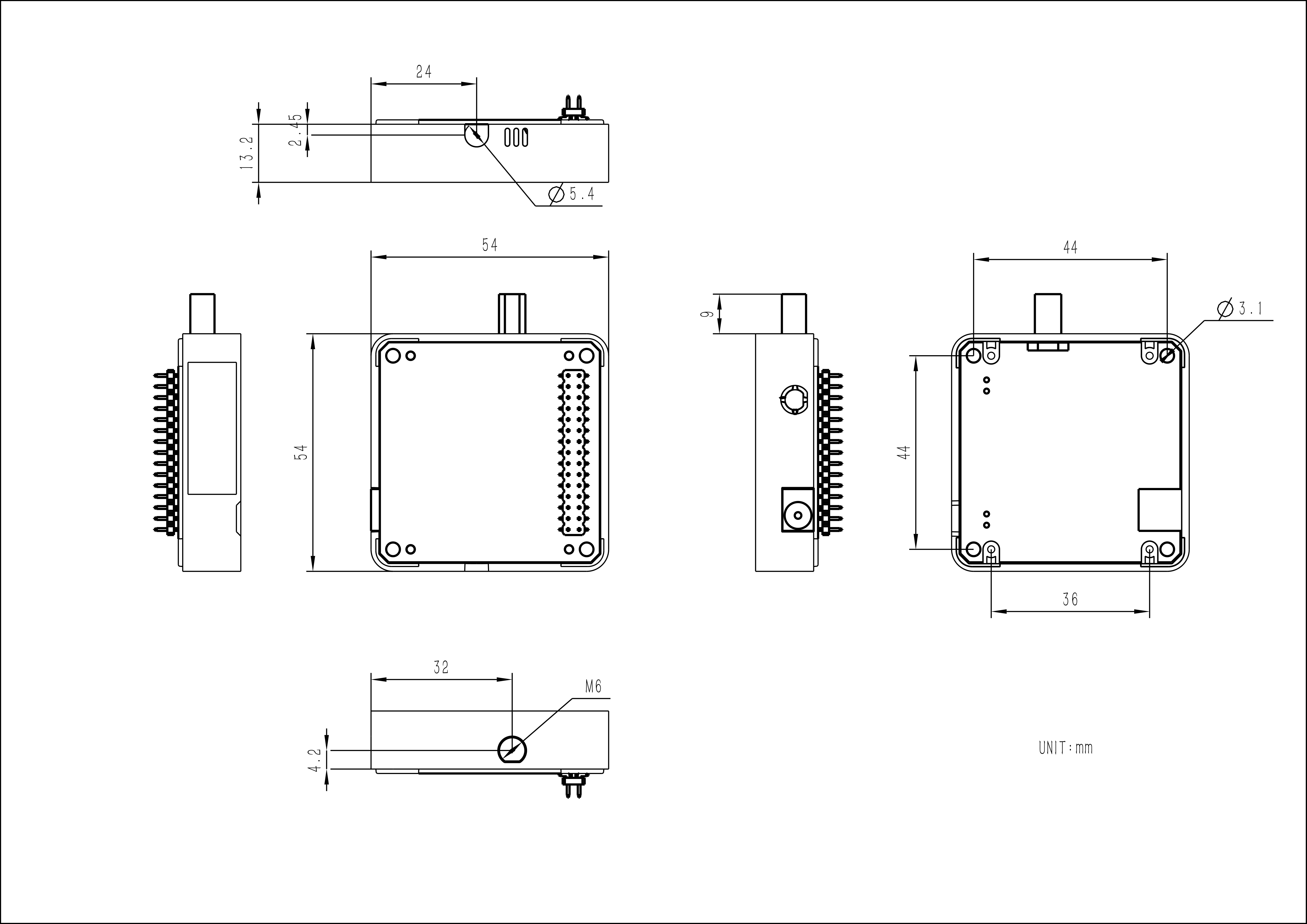
| Product Size | 54.0 x 54.0 x 13.2mm |
| Product Weight (Including Antenna) | 37.0g |
| Package Size | 165.0 x 60.0 x 36.0mm |
| Gross Weight | 70.0g |
Learn
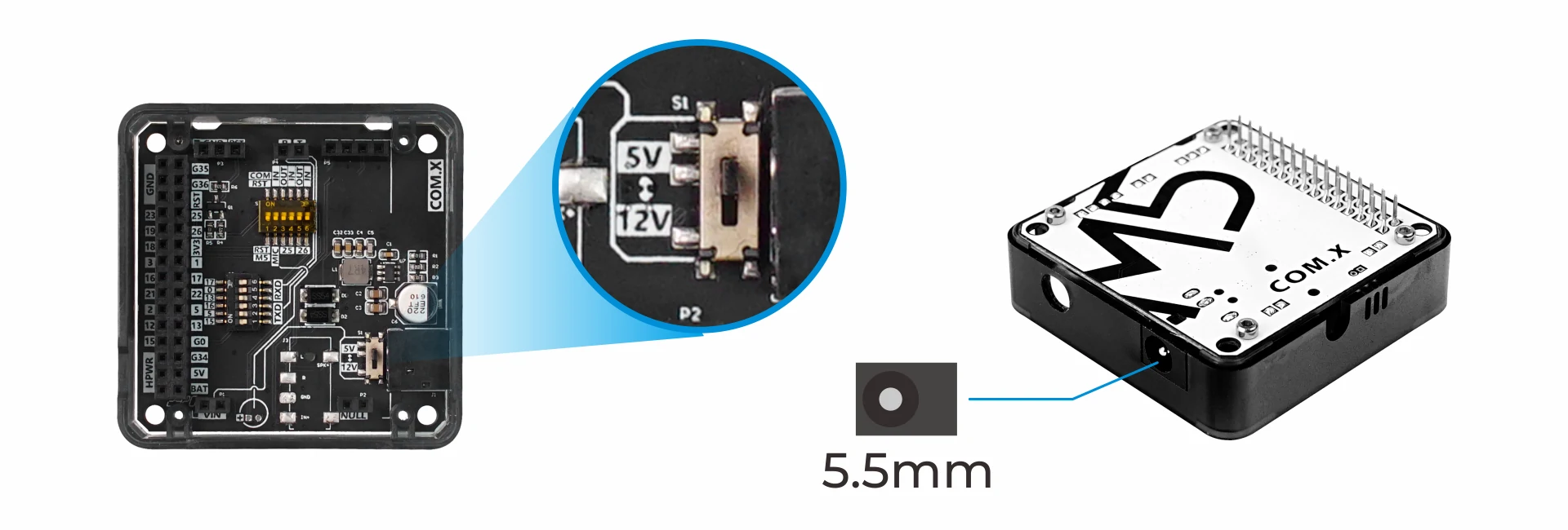
Power supply switching
The module base has a DC power input interface. When using this interface to connect to the power supply, strictly adhere to the input range (5-12V) to prevent module damage. The internal power DIP switch can adjust the voltage level of the internal terminal VIN to adapt to different modules.
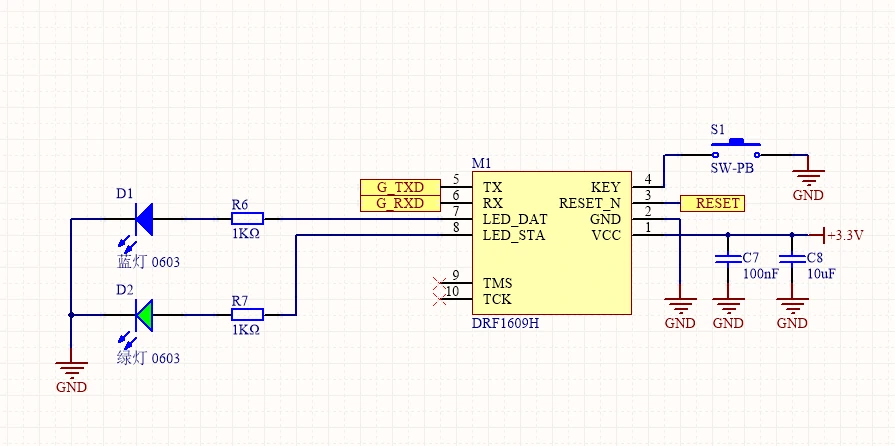
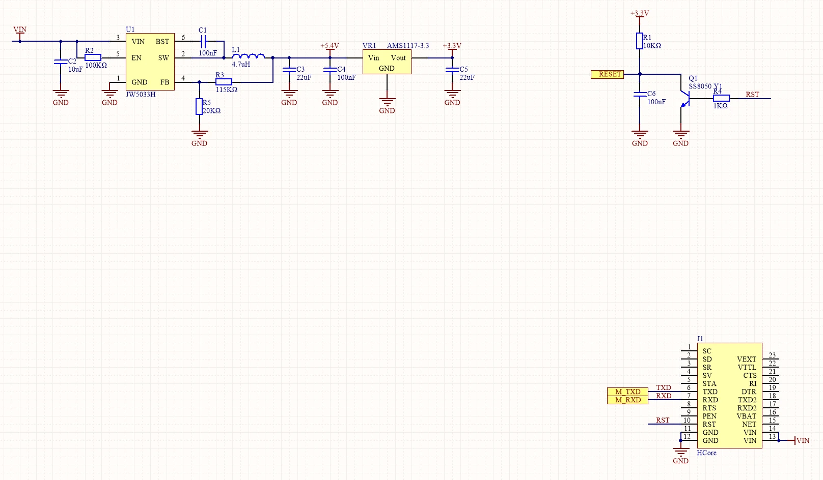
Schematics
1/2
PinMap
M5-Bus
Switch
The pins marked
SW on the M5-Bus below can be switched via DIP switches to adapt to different main controllers.| PIN | LEFT | RIGHT | PIN |
|---|---|---|---|
| GND | 1 | 2 | |
| GND | 3 | 4 | |
| GND | 5 | 6 | |
| 7 | 8 | ||
| 9 | 10 | ||
| 11 | 12 | 3V3 | |
| 13 | 14 | ||
| TXD (SW) | 15 | 16 | RXD (SW) |
| 17 | 18 | ||
| 19 | 20 | TXD (SW) | |
| 21 | 22 | RXD (SW) | |
| TXD (SW) | 23 | 24 | RXD (SW) |
| 25 | 26 | ||
| 27 | 28 | 5V | |
| 29 | 30 |
Model Size
Datasheets
Softwares
Arduino
UiFlow1
UiFlow2
Protocol
Easyloader
| Easyloader | Download Link | Notes |
|---|---|---|
| Module COMX Zigbee P2P Chat Room Example Easyloader with M5Core | download | / |
| Module COMX Zigbee Coordinator Example Easyloader with M5Core | download | / |
| Module COMX Zigbee End Device Example Easyloader with M5Core | download | / |
Video
Page Tools