

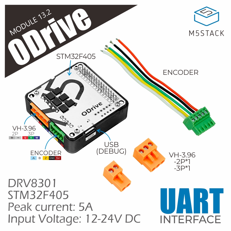
Module13.2 BLDC Drvier
SKU:M036

Description
Module13.2 BLDC Drvier is a high-performance servo motor driver module launched by M5Stack, based on the open-source motion control solution ODrive. It supports control of a single three-phase servo motor, with a peak drive current of up to 5A. While offering high-speed motor control capability, it also provides an encoder signal interface, which enables high-precision motion control and positioning. The module uses a UART communication interface and is compatible with the official ODrive configuration tool and protocol (via the host tool, various motor motion modes can be configured to make motor operation smoother and more stable).
Features
- Supports single three-phase servo motor drive
- Peak drive current 5A
- DC 12 ~ 24V power input interface (requires adapter output current up to 5A)
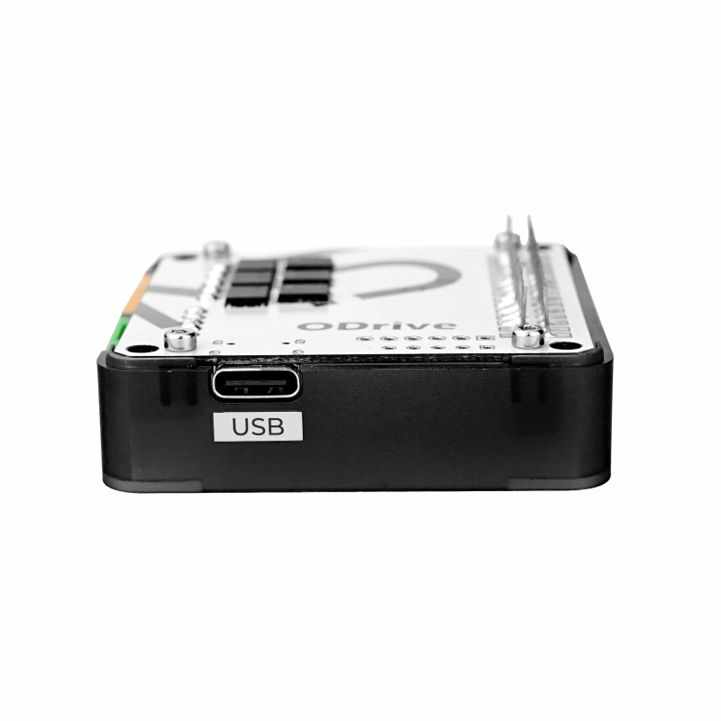
- Communication interface: UART
- Integrated encoder signal interface
Includes
- 1 x Module13.2 BLDC Drvier
- 1 x 3.96-3P Terminal
- 1 x 3.96-2P Terminal
- 1 x 2.54-5P Terminal (with cable)
Applications
- High-precision motion control
- Servo motor drive
Specifications
| Specification | Parameter |
|---|---|
| Maximum Drive Current | 5A |
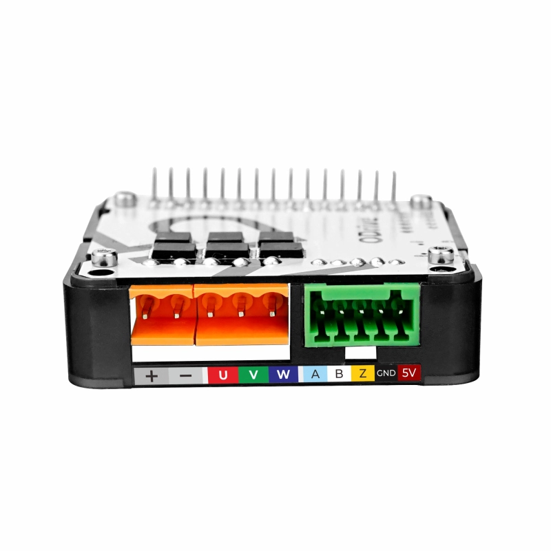
| Interface Type | 3.96-2P (Power), 3.96-3P (Motor), 2.54-5P (Encoder) |
| ODrive Hardware Version | v3.5-24V |
| ODrive Firmware Version | 0.5.1 |
| Input Power Supply | DC 12 ~ 24V |
| Product Size | 54.2 x 54.2 x 19.7mm |
| Product Weight | 22.5g |
| Package Size | 95.0 x 65.0 x 25.0mm |
| Gross Weight | 42.3g |
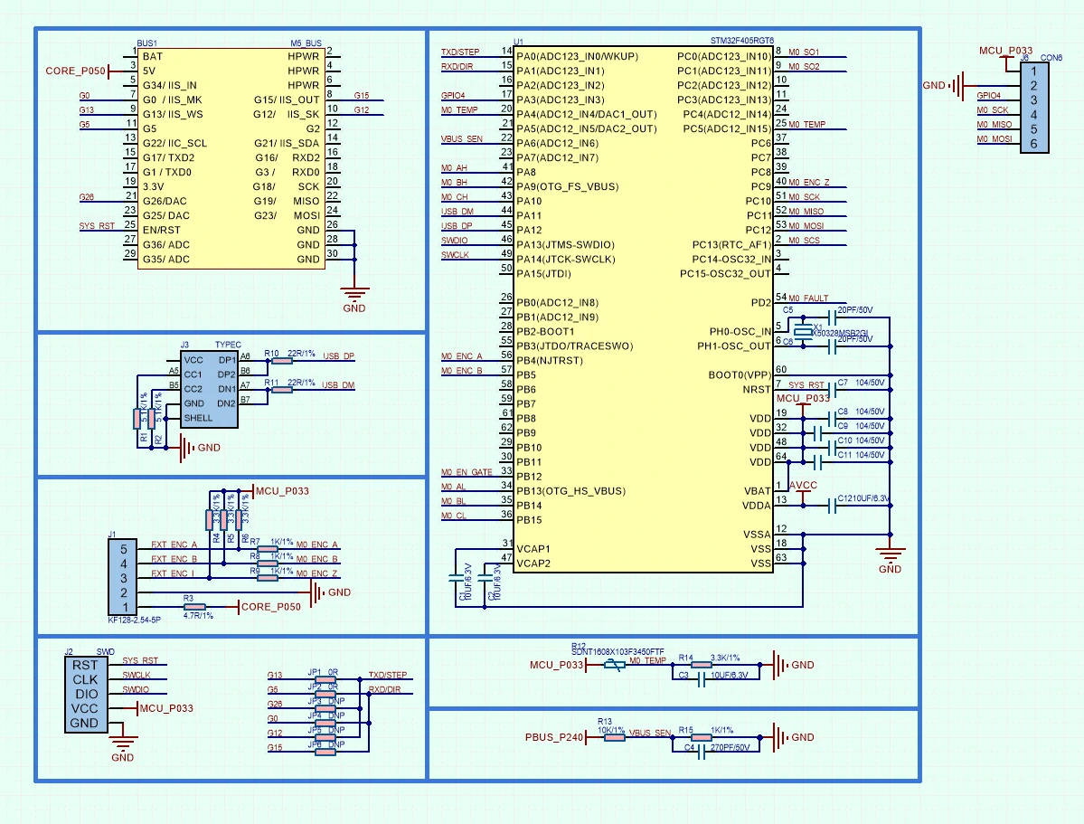
Schematics
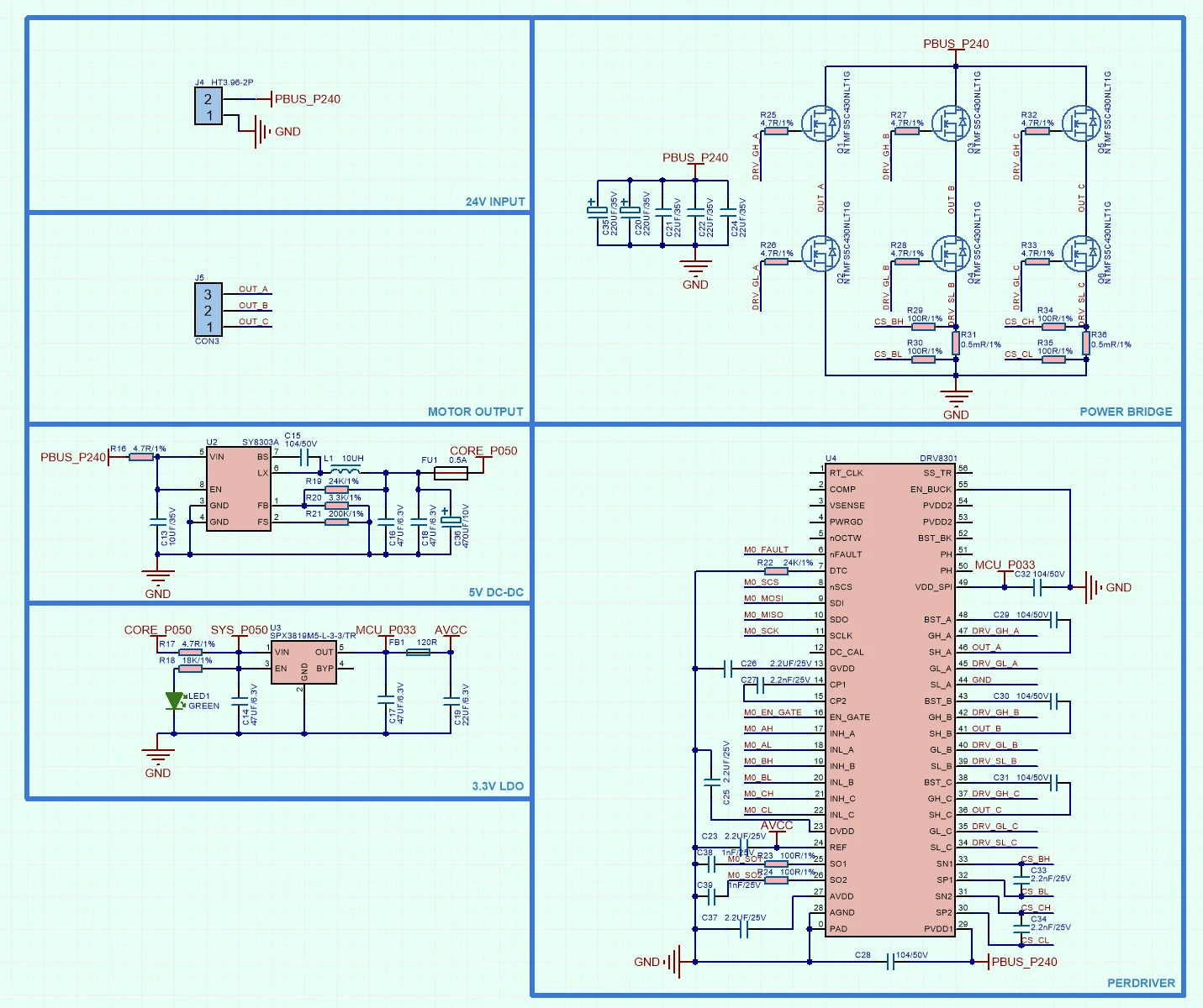
1/2
PinMap
M5-Bus
| PIN | LEFT | RIGHT | PIN |
|---|---|---|---|
| GND | 1 | 2 | |
| GND | 3 | 4 | |
| GND | 5 | 6 | RST |
| 7 | 8 | ||
| 9 | 10 | TXD / STEP | |
| 11 | 12 | ||
| 13 | 14 | ||
| 15 | 16 | ||
| 17 | 18 | ||
| 19 | 20 | RXD / DIR | |
| TXD / STEP | 21 | 22 | TXD / STEP |
| RXD / DIR | 23 | 24 | RXD / DIR |
| 25 | 26 | ||
| 27 | 28 | 5V | |
| 29 | 30 |
Model Size

Datasheets
Softwares
Arduino
Example Description
This example uses the ODrive module to control a servo motor for high-speed and precise rotation. Note: Before use, you need to configure relevant parameters using ODriveTool according to the connected motor model.
UiFlow2
ODriveTool
odrivetool is the configuration and debugging software paired with ODrive. It can be used to configure motor parameters. This tutorial demonstrates how to install and use odrivetool on the
Linux platform.- Use the following command to install odrivetool v0.5.1. Environment requirement:
python3.
pip3 install odrive==0.5.1.post0- Add
~/.local/binto the system environment variable. Execute the following command, and insertexport PATH=$PATH:~/.local/binto the end of the text.
vim ~/.bashrc- Execute
odrivetoolin the command line to run the tool. Connect the ODrive module to the computer and wait for odrivetool to recognize it. After successful connection, enterodrv0.vbus_voltageto test and get the driver board voltage.
$odrivertool

ODrive control utility v0.5.1.post0
Website: https://odriverobotics.com/
Docs: https://docs.odriverobotics.com/
Forums: https://discourse.odriverobotics.com/
Discord: https://discord.gg/k3ZZ3mS
Github: https://github.com/madcowswe/ODrive/

Please connect your ODrive.
You can also type help() or quit().

Connected to ODrive 306A396A3235 as odrv0

In [1]: odrv0.vbus_voltage- Common configuration commands.
// Configure motor current limit
odrv0.axis0.motor.config.current_lim [A].

// Configure motor speed limit
odrv0.axis0.controller.config.vel_limit

// Configure the resistance value for braking resistor
odrv0.config.brake_resistance

// Save configuration
odrv0.save_configuration()- For more details, please check the official ODrive documentation