
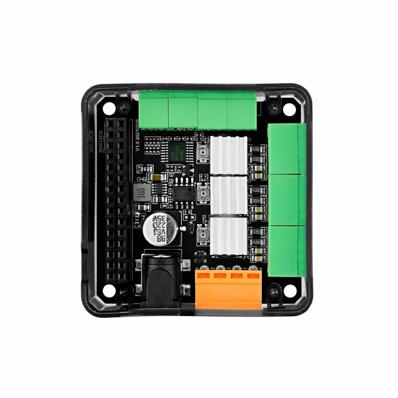
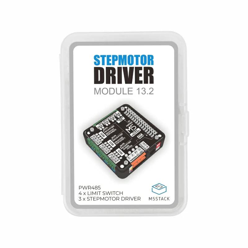
Module13.2 Stepmotor Driver
SKU:M039
Description
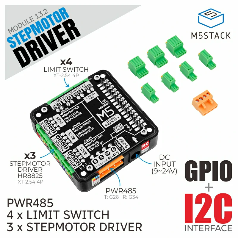
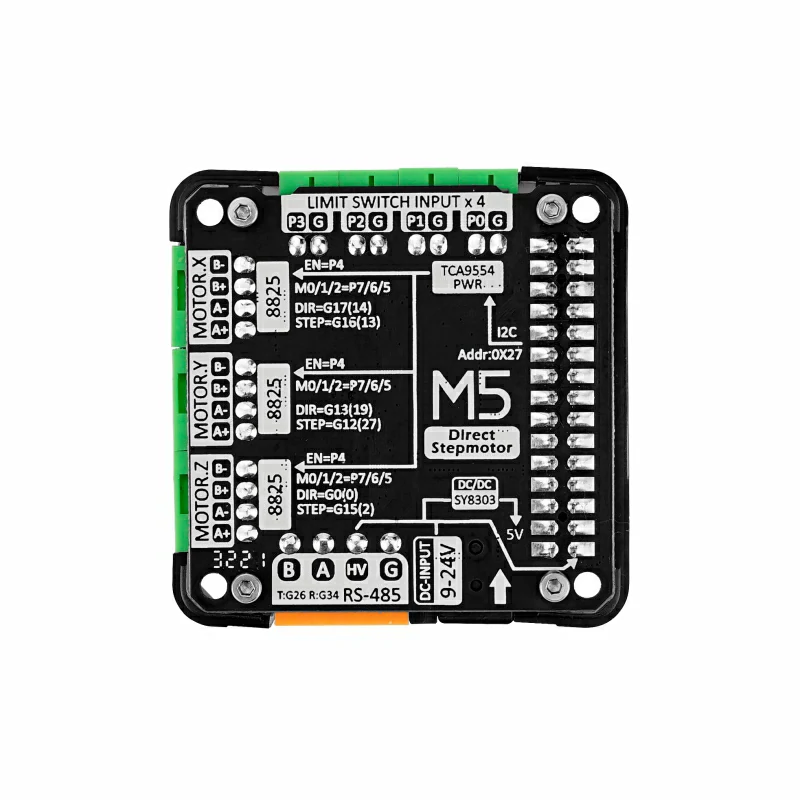
Module13.2 Stepmotor Driver is a stepper motor driver compatible with M5 controllers, utilizing the HR8825 stepper motor driver chip, providing 3 dual-channel stepper motor control interfaces. When stacked with an M5 controller, the internal ESP32 generates signals directly connected to the driver chip, enabling independent control or multi-axis motor coordination. The module integrates a TCA9554 IO expansion chip, offering 4 sets of input signal terminals + 3 sets of stepper motor microstep control + 1 set of driver chip enable control, controlled via the I2C interface. It can monitor and control the status of these 8 expanded IOs, suitable for external limit switches, dynamic microstep adjustment, and motor braking functions. The module also integrates a PWR485 communication interface (RS485 + 9-24V power input) and a DC-JACK, allowing for flexible power supply while enabling communication. It supports UIFlow graphical programming and ESP32-GRBL firmware, web control, making it easy to configure signal output for more precise control of stepper motors. This module is suitable for various stepper motor motion control scenarios, such as printers, robotic arms, etc.
Note
Features
- Three-axis HR8825 stepper motor driver
- Compatible with bipolar stepper motors
- Each channel has a current adjustment potentiometer, with a driving current of up to 1.5A
- Supports multiple microstep modes, up to
1/32STEP microstep - Multiple sets of signal input interfaces
- PWR485 communication interface (RS485 + 9-24V power input)
- DC-JACK terminal input (9-24V)
- Built-in DC-DC, integrated 9-24V to 5V circuit
- Development platforms:
- Arduino, UIFlow
Includes
- 1 x Module13.2 Stepmotor Driver
- 4 x 2.54-2P terminals
- 3 x 2.54-4P terminals
- 1 x 3.96-4P terminal
Applications
- Printers
- Scanners
- CNC engraving machine control
- Motion module control
Specifications
| Specification | Parameter |
|---|---|
| Stepper Motor Driver Chip | HR8825 |
| IO Expansion Chip | TCA9554 |
| Communication Interface | I2C @0x27 |
| Supported Microstepping Modes | FULL, 1/2, 1/4, 1/8, 1/16, 1/32 |
| Max Driving Current Per Channel | 1.5A |
| Input Signal Terminal Spec | 2.54-2P |
| Motor Wiring Terminal Spec | 2.54-4P |
| RS485 Wiring Terminal Spec | 3.96-4P |
| Product Size | 54.2 x 54.2 x 13.2mm |
| Product Weight | 40.0g |
| Package Size | 95.0 x 65.0 x 25.0mm |
| Gross Weight | 60.0g |
Learn
Microstep Truth Table
| M2 | M1 | M0 | Resolution |
|---|---|---|---|
| 0 | 0 | 0 | FULL |
| 0 | 0 | 1 | 1/2 |
| 0 | 1 | 0 | 1/4 |
| 0 | 1 | 1 | 1/8 |
| 1 | 0 | 0 | 1/16 |
| 1 | 0 | 1 | 1/32 |
| 1 | 1 | 0 | 1/32 |
| 1 | 1 | 1 | 1/32 |
TCA9554 Registers
I2C Addr: 0x27
Use register 0x00 to read status
Use register 0x01 to write status
Set the corresponding bit in register 0x02 to 1 for polarity inversion, 0 for no inversion
Set the corresponding bit in register 0x03 to 1 for input mode, 0 for output mode.
The pin correspondence for the above register bytes is shown in the table below.
| Bit | Description | R/W |
|---|---|---|
| 7 | P7 Microstep adjustment bit M0 | R/W |
| 6 | P6 Microstep adjustment bit M1 | R/W |
| 5 | P5 Microstep adjustment bit M2 | R/W |
| 4 | P4 DRV EN Driver chip enable | R/W |
| 3 | P3 Input signal 3 | R/W |
| 2 | P2 Input signal 2 | R/W |
| 1 | P1 Input signal 1 | R/W |
| 0 | P0 Input signal 0 | R/W |
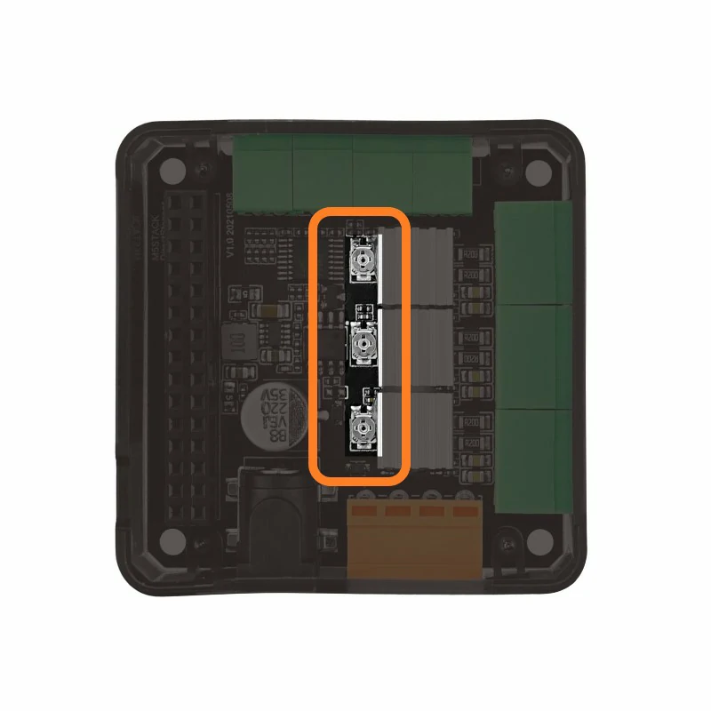
Driving Current Adjustment
Different stepper motors may require different driving currents. The current output can be adjusted using the metal knob on the module. To prevent motor overheating or damage, adjust the knob slowly and observe the motor status or use an ammeter to determine the appropriate driving current.
PinMap
M5-Bus
| PIN | LEFT | RIGHT | PIN |
|---|---|---|---|
| GND | 1 | 2 | |
| GND | 3 | 4 | |
| GND | 5 | 6 | |
| 7 | 8 | RS485_TX | |
| 9 | 10 | ||
| 11 | 12 | 3V3 | |
| 13 | 14 | ||
| STEP_X | 15 | 16 | DIR_X |
| SDA | 17 | 18 | SCL |
| 19 | 20 | ||
| STEP_Y | 21 | 22 | DIR_Y |
| STEP_Z | 23 | 24 | DIR_Z |
| HPWR | 25 | 26 | RS485_RX |
| HPWR | 27 | 28 | 5V |
| HPWR | 29 | 30 |
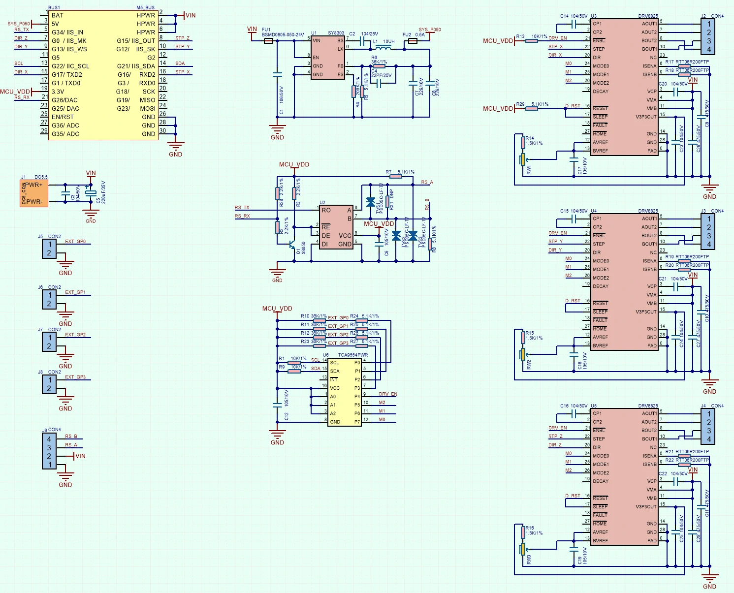
Schematics
Datasheets
Softwares
Arduino
1.0.3. Versions higher than this may cause compilation issues. For usage instructions and WEB-UI control, please refer to ESP32-GRBL-WIKIUiFlow1
Video
Product Comparison
| Feature | GRBL 13.2 MODULE | STEPMOTOR DRIVER |
|---|---|---|
| Control Method | I2C communication | Pulse signal |
| Firmware | Onboard STM32, built-in GRBL firmware | No firmware, can be directly driven by ESP32 signals |
| Stackable Modules | 2 | 1 |
| Driver Chip | DRV8825 | HR8825 |
| Microstep Adjustment | DIP switch | TCA9554 chip control |
| Interfaces | 3 sets of limit switch interfaces | 4 sets of custom signal input interfaces + RS485 communication interface |