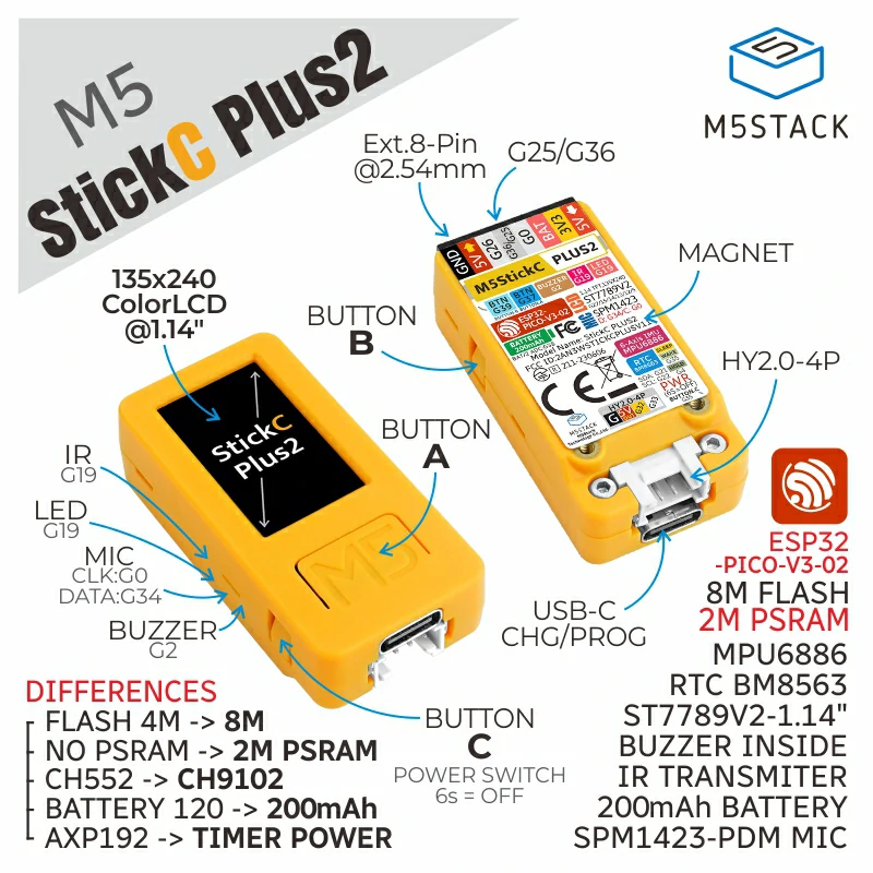
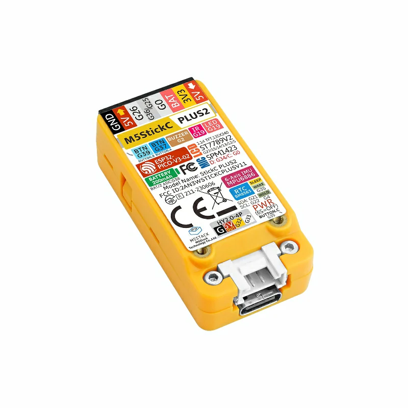
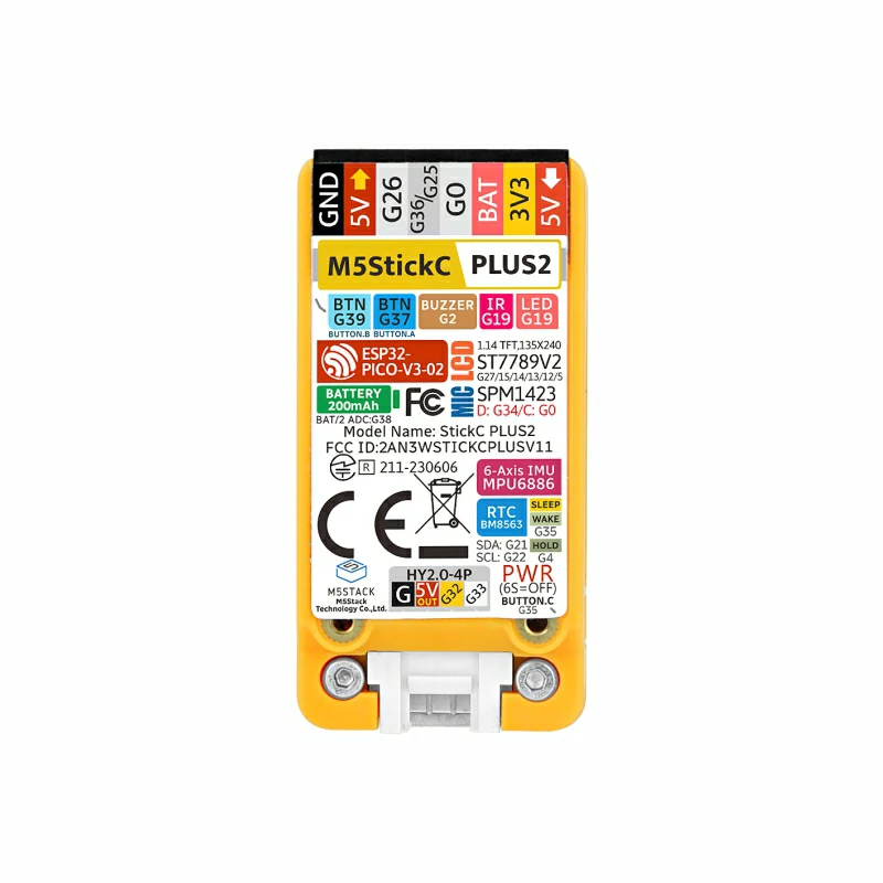
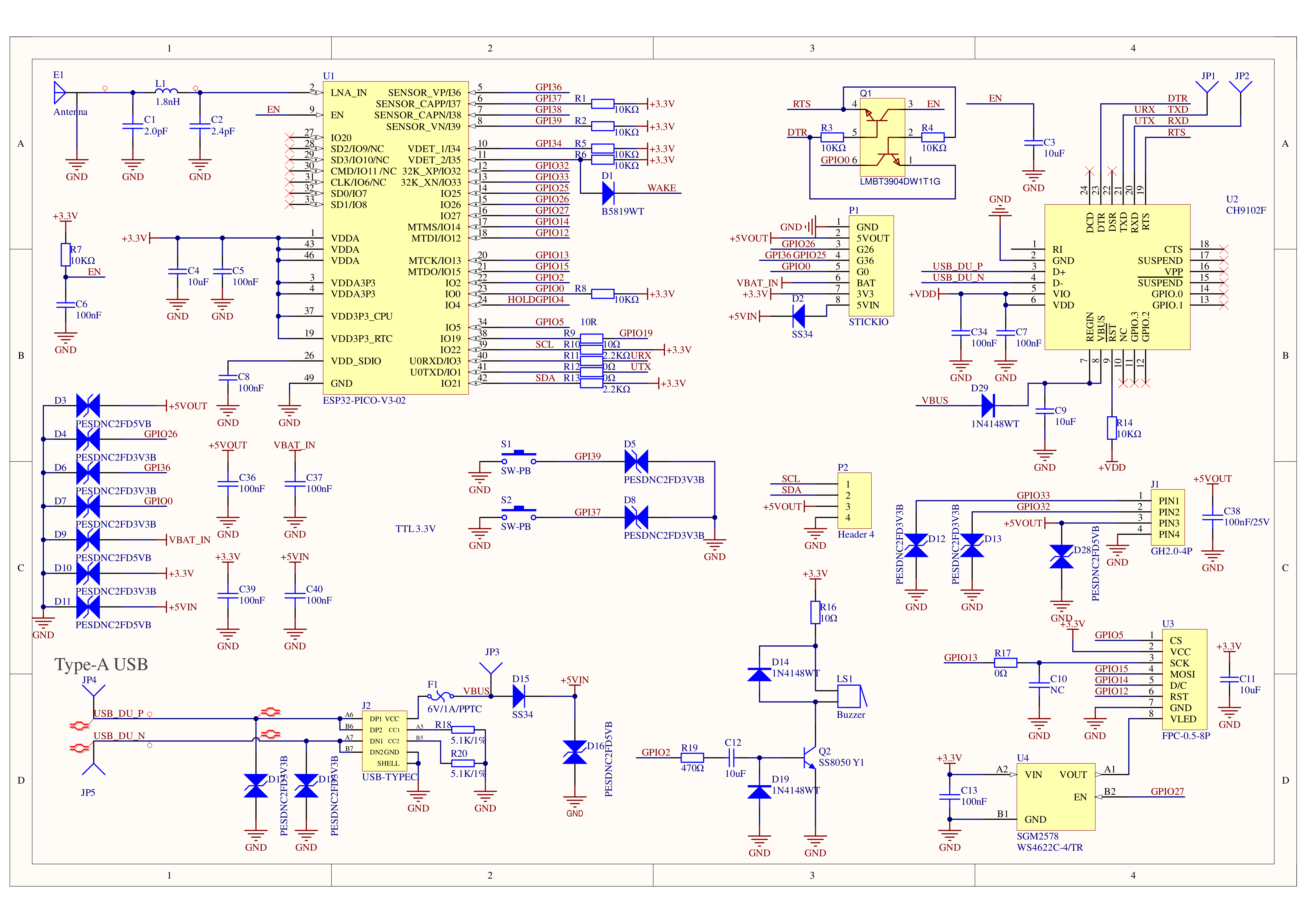
StickC-Plus2 is the iterative version of StickC-Plus. It is powered by the ESP32-PICO-V3-02 chip, providing Wi-Fi connectivity. Within its compact body, it integrates a rich variety of hardware resources, including IR emitter, RTC, microphone, LED, IMU, buttons, buzzer, and more. It features a 1.14-inch TFT display driven by the ST7789V2 with a resolution of 135 × 240.
The battery capacity has been increased to 200mAh, and the interface is compatible with both HAT and Unit series modules.
This sleek and compact development tool can ignite unlimited creativity. StickC-Plus2 helps you quickly build IoT product prototypes and greatly simplifies the entire development process. Even beginners who are new to programming can create interesting applications and apply them in real life.
This tutorial will introduce how to program and control the StickC-Plus2 device using the Arduino IDE.
Note
Port Not Recognized
When using a C-to-C cable, if the port cannot be recognized, please perform the following power-on procedure: disconnect StickC-Plus2, power it off (long-press the power button until the green LED lights up), then reconnect the USB cable to power on.
Features
Developed based on ESP32-PICO-V3-02, supports Wi-Fi
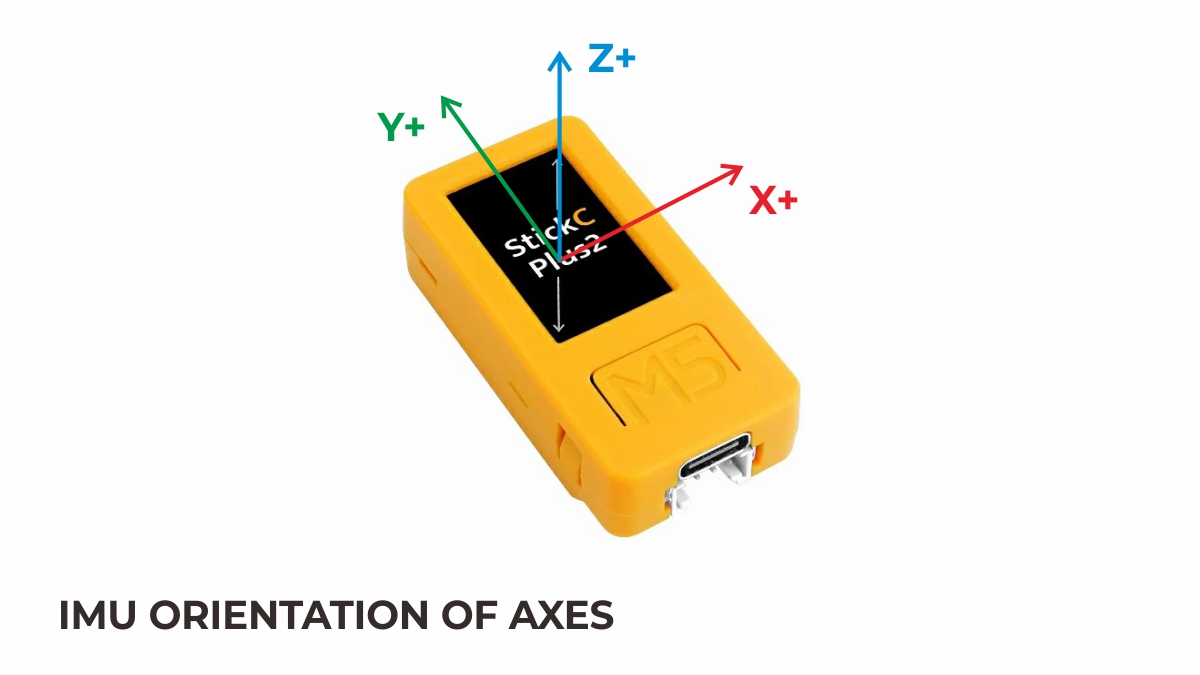
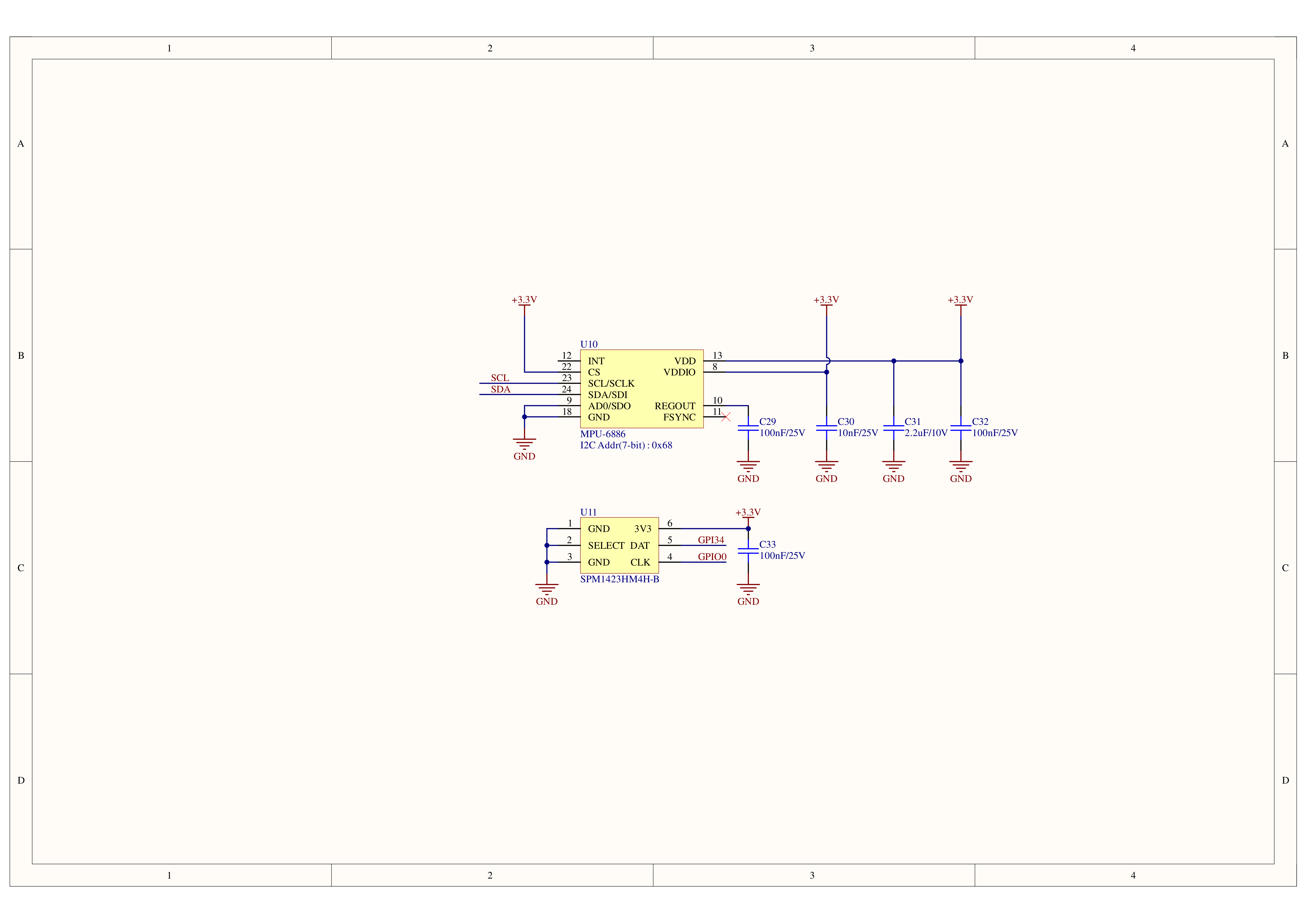
Built-in 3-axis accelerometer and 3-axis gyroscope
Integrated infrared emitter
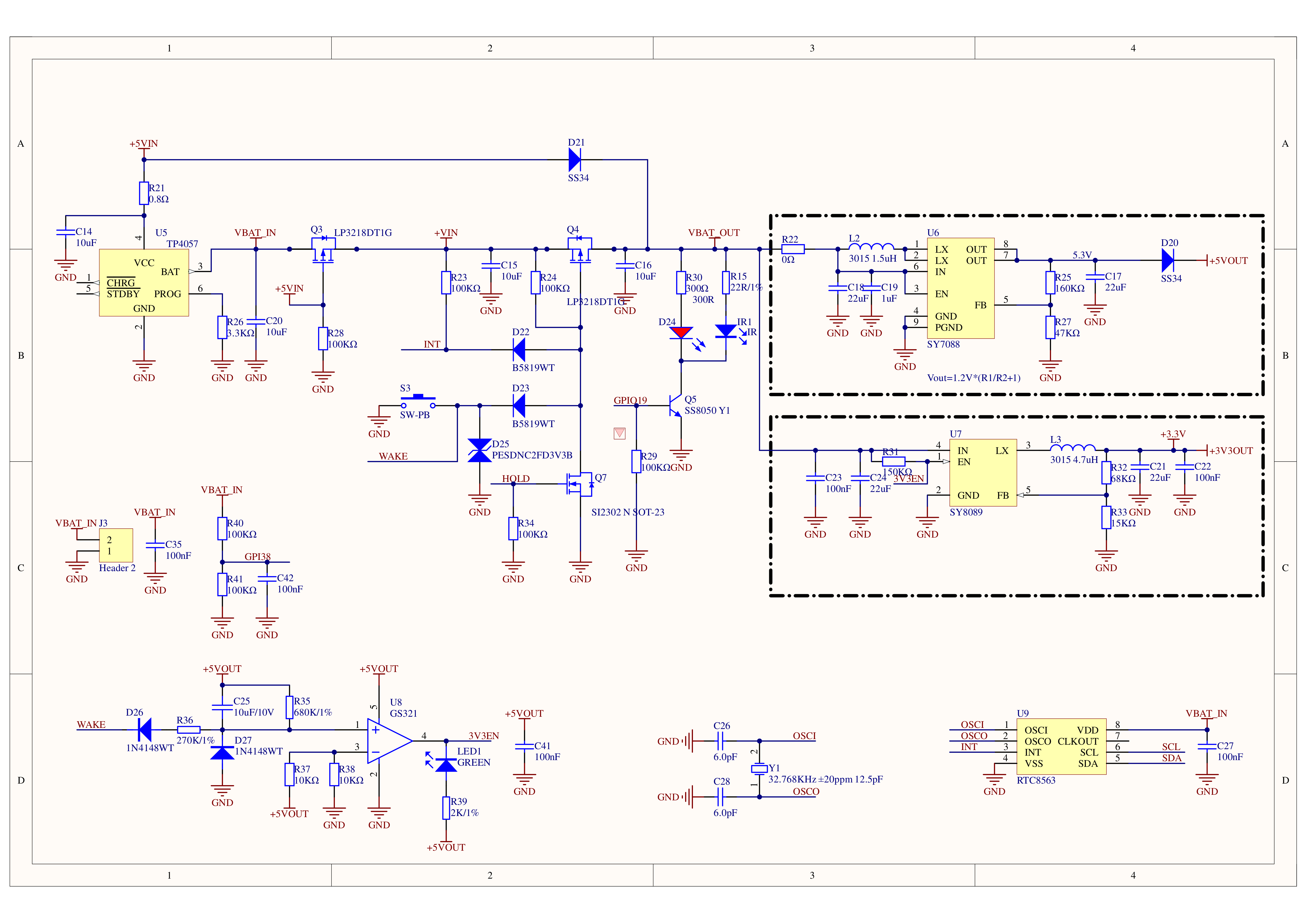
Built-in RTC
Integrated microphone
User button, LCD (1.14 inch), power/reset button
200mAh lithium battery
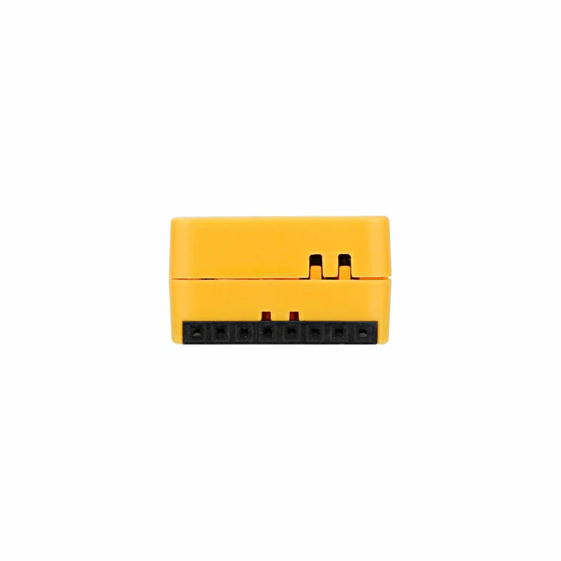
Expansion interface
Integrated passive buzzer
Wearable & mountable
Development Platform
UiFlow1
UiFlow2
Arduino IDE
ESP-IDF
PlatformIO
Includes
1 × StickC-Plus2
Applications
Wearable devices
IoT controller
STEM education
DIY projects
Smart-home devices
Specifications
Specification
Parameter
SoC
ESP32-PICO-V3-02@Dual-Core Processor, up to 240MHz
Flash
8MB
PSRAM
2MB Quad
Wi-Fi
2.4 GHz Wi-Fi
Input Voltage
5V@500mA
Interface
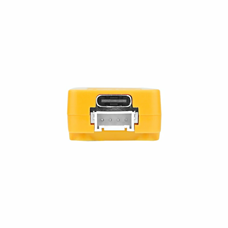
USB Type-C x 1, HY2.0-4P (I2C+I/O+UART) x 1
LCD Screen
1.14-inch, 135 x 240 Colorful TFT LCD, ST7789v2
Microphone
SPM1423
Button
Custom Button x 3
LED
Green LED x 1 (Non-programmable) (Sleep State Indicator) Red LED x 1 (Shared control pin G19 with IR emitter tube)
RTC
BM8563
Buzzer
Onboard Buzzer
IMU
MPU6886
Antenna
2.4 GHz 3D Antenna
External Pins
G0, G25/G26, G36, G32, G33
Battery
200mAh@3.7V, inside
Operating Temperature
0 ~ 40°C
Shell Material
Plastic (PC)
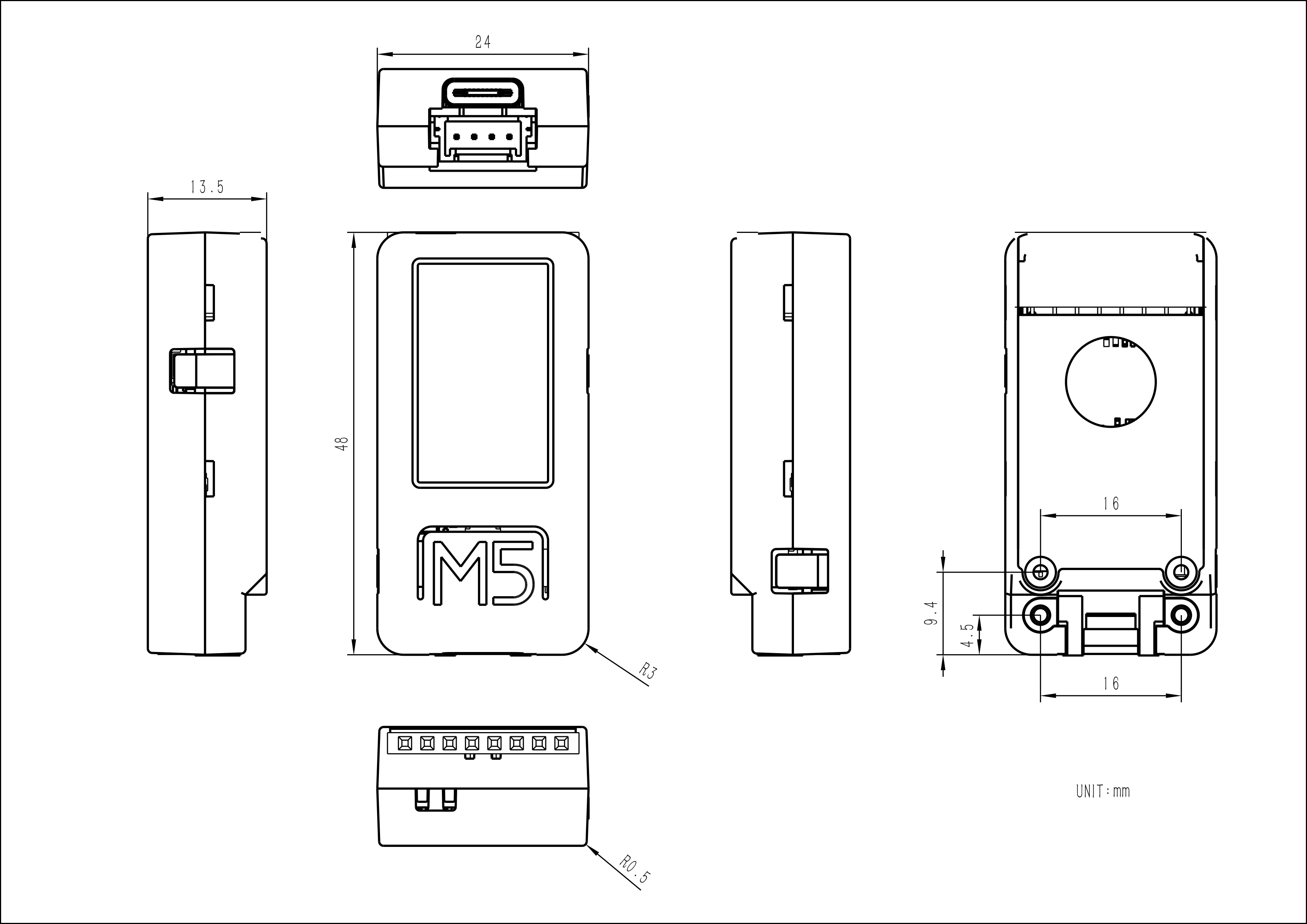
Product Size
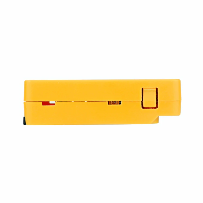
48.0 x 24.0 x 13.5mm
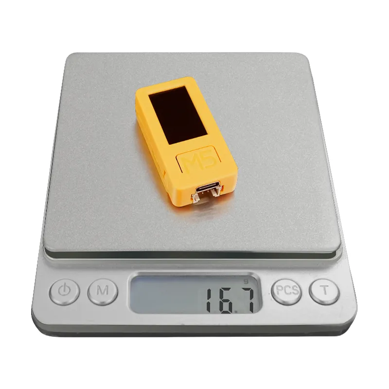
Product Weight
16.7g
Package Size
110.0 x 65.0 x 15.0mm
Gross Weight
26.3g
Operation Instructions
Power On/Off
Power-on: Press the “BUTTON C” for more than 2 seconds, or wake up via the RTC IRQ signal. After the wake-up signal is triggered, the program must set the HOLD pin (G4) to high (1) to keep the power on, otherwise the device will shut down again. Power-off: Without external USB power, press “BUTTON C” for more than 6 seconds, or set HOLD (GPIO4)=0 in the program to power off. While USB is connected, pressing “BUTTON C” for more than 6 seconds will turn off the screen and enter sleep mode (not a full power-off).
Click the links below to download the driver that matches your operating system. The package contains CP34X drivers (for CH9102). After extracting the archive, run the installer that matches your OS bit-depth. If you encounter issues such as timeout or “Failed to write to target RAM” during downloading, please try reinstalling the driver.
EasyLoader is a lightweight program flasher that comes with a demonstration firmware. By following a few simple steps, you can flash it to the controller for quick functional verification.
Removed AXP192 power management chip; main controller changed from ESP32-PICO-D4 to ESP32-PICO-V3-02; power on/off method is different
Version changed to v2
2021.12
Added sleep and wake-up functions; version changed to v1.1
/
/
First release
/
Product Comparison
To compare information on the Stick series products, you can visit the Product Selection Table, check the target products, and get the comparison results. The selection table covers key information such as core parameters and functional features, and supports comparison of multiple products simultaneously.
Hardware Differences
Product Name
SoC
Power Management
Battery Capacity
Memory
USB-UART Chip
Color
StickC-Plus
ESP32-PICO-D4
AXP192
120 mAh
520 KB SRAM + 4 MB Flash
CH522
Red-orange
StickC-Plus2
ESP32-PICO-V3-02
/
200 mAh
2 MB PSRAM + 8 MB Flash
CH9102
Orange
Pin Differences
Product Name
IR
LED
TFT
BUTTON A
BUTTON B
BUTTON C (WAKE)
HOLD
Battery Voltage Detect
M5STICKC PLUS
G9
G10
MOSI (G15) CLK (G13) DC (G23) RST (G18) CS (G5)
G37
G39
Regular button
/
Via AXP192
M5STICKC PLUS2
G19
G19
MOSI (G15) CLK (G13) DC (G14) RST (G12) CS (G5)
G37
G39
G35
G4
G38
Power On/Off Differences
Product Name
Power On
Power Off
StickC-Plus
Press reset button (BUTTON C) for at least 2 s
Press reset button (BUTTON C) for at least 6 s
StickC-Plus2
Press “BUTTON C” for more than 2 s, or wake via RTC IRQ. After wake-up, set HOLD (G4)=1 in the program to keep power on, otherwise the device will shut down again.
Without USB power, press “BUTTON C” for more than 6 s, or set HOLD (GPIO4)=0 in the program to power off. With USB connected, pressing “BUTTON C” for more than 6 s will turn off the screen and enter sleep, but not a full power-off.
Because StickC-Plus2 removes the PMIC AXP192, the power-on/off method differs from previous versions. As mentioned at the beginning of this document, the operation is largely similar, but the supported libraries will differ. Wi-Fi and IR signal strength have both been improved compared to the previous model.