Unit TimerPWR
SKU:U189


Description
Unit TimerPWR is a timed power supply unit with main functions such as "charge/discharge + timed switching + screen display + boost output". It features an embedded STM32 microcontroller for implementing RTC (Real-Time Clock) and overall control, allowing users to set automatic power-on and power-off times according to their needs.
The unit is powered via a Type-C interface and can be connected to a rechargeable battery through a 1.25-2P interface. It includes a built-in battery charging circuit that supports a charging current of 330mA. Additionally, it features a built-in DC-DC boost circuit, which can provide a 5V/800mA (1400mA@1C battery-powered) power output to external devices through the Grove port. Moreover, it includes an INA3221 sensor for real-time monitoring of input and output current and voltage.
This unit is equipped with a 0.66-inch OLED display and two side buttons for user interaction, enabling users to easily view the system's real-time status and modify settings. Users can configure settings using the side buttons or via I2C commands through the Grove interface. This product is suitable for applications such as smart homes, industrial automation, and timed control devices.
Features
- RTC cyclic timing control
- Battery-powered
- Built-in DC-DC boost circuit
- Current/voltage monitoring
- OLED display
- Grove interface
- Button-controlled power on/off mode
Includes
- 1 x Unit TimerPWR
- 1 x HY2.0-4P Grove cable (20cm)
Applications
- Timed control devices
- Portable electronic devices
- Sensor node power supply
Specifications
| Specification | Parameters |
|---|---|
| MCU | STM32G031G8U6 |
| Input Voltage | Supports 5V DC input (via Type-C interface) |
| Output Voltage | Built-in DC-DC boost circuit, outputs 5V for external devices |
| Battery Power | 3.7V polymer lithium battery |
| Display | 0.66-inch OLED display, 64x48 resolution, SPI communication |
| Interfaces | Type-C interface: for battery charging (cannot directly power the Grove port) Grove interface: for external sensors and module expansion, supports communication and external power supply Battery interface: 1.25mm@2P |
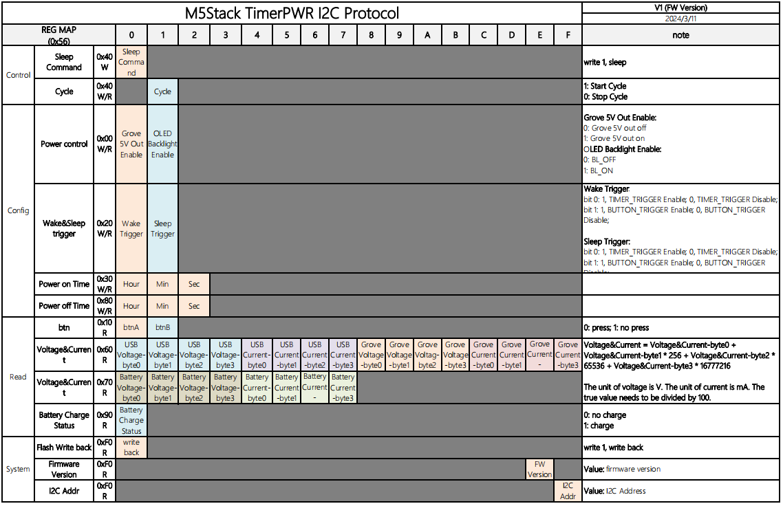
| I2C Communication Address | 0x56 |
| Current Sensor | INA3221 |
| Charging Current | DC 5V@330mA |
| Charging Chip | LGS4056H |
| Charging Temperature | 55°C |
| Grove Port Max Output Current | Related to battery capacity and discharge capability, e.g.: 1400mAh@1C 3.7V:DC4.96V@800mA 500mAh@1C 3.7V: DC4.97V@700mAh 110mAh@1C 3.7V: DC5.03V@400mAh |
| Standby Current | DC4.2V@36.67uA |
| Operating Temperature | 0 ~ 40°C |
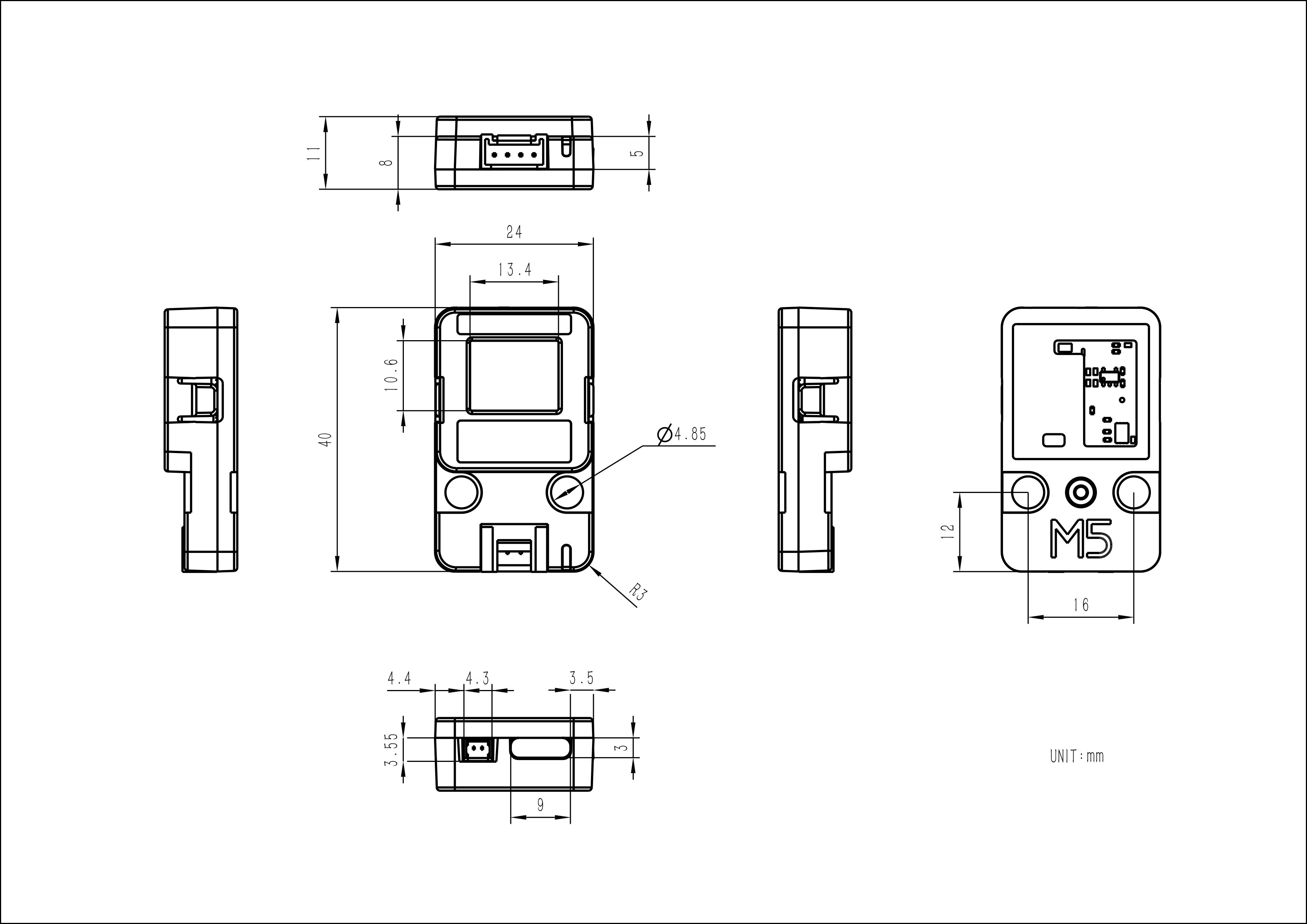
| Product Size | 40.0 x 24.0 x 11.0mm |
| Product Weight | 7.5g |
| Package Size | 138.0 x 93.0 x 12.0mm |
| Gross Weight | 13.2g |
Learn
Power Supply
Schematics


PinMap
Unit TimerPWR
| HY2.0-4P | Black | Red | Yellow | White |
|---|---|---|---|---|
| PORT.A | GND | 5V | SDA | SCL |
STM32G031G8U6
| STM32G031G8U6 | PB6 | PB7 | PA11 | PA12 | PB4 | PA0 | PA4 |
|---|---|---|---|---|---|---|---|
| I2C1 (GROVE) | SCL1 | SDA1 | |||||
| I2C2 (INA3221) | SCL2 | SDA2 | |||||
| LED (Charging Indicator) | CHAG | ||||||
| Button A | BTN_A | ||||||
| Button B | BTN_B |
OLED
| STM32G031G8U6 | PA2 | PA1 | PA6 | PA7 | PB0 | PB1 |
|---|---|---|---|---|---|---|
| OLED | OLED_MOSI | OLED_SCK | OLED_DC | OLED_RST | OLED_CS | BL_EN |
Model Size

Datasheets
Softwares
Arduino
UiFlow1
UiFlow2
Internal Firmware
Protocol

Video
- Unit TimerPWR Product Introduction and Case Demonstration
- UiFlow2 Use