
Unit Catch
SKU:U102
Description
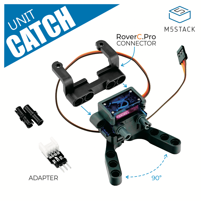
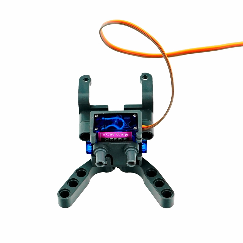
Unit Catch is a gripper powered by the SG92R servo motor. The servo uses a PWM signal to drive the gear rotation, allowing control of the gripper for gripping and releasing actions. Structurally, it features a design compatible with LEGO 8 mm round holes. You can integrate it with other LEGO components to build creative control structures such as robotic arms and gripper vehicles.
Note
Rotation Angle
Since the opening and closing angle of the gripper is 90°, please control the servo rotation angle within 0-45° (PWM: frequency 50Hz, 0°-45° (pulse: 0.5ms-1ms)) to prevent stalling that may cause the servo to burn out.
Features
- SG92R servo motor
- PWM signal drive
- LEGO hole compatible
- Gripper opening/closing angle of 90°
- Compatible with RoverC
- Supported input voltage: 4.2-6V
- Development platforms: UiFlow, MicroPython, Arduino
Includes
- 1 x Unit Catch
- 1 x HY2.0-4 Adapter
- 1 x RoverC.Pro Connector
Applications
- Gripper robot
- Servo robotic arm gripper
Specifications
| Specification | Parameter |
|---|---|
| Servo Model | SG92R |
| Drive Signal | PWM: frequency 50Hz, 0°-45° (pulse:0.5ms-1ms) ° |
| Operating Frequency | 50Hz |
| Gripper Angle | 90° |
| Input Voltage Range | 4.2-6V |
| Dead Band | 10us |
| Output Torque | 2.5kg/cm at 4.8V |
| Output Speed | 0.1sec/60° at 4.8V |
| Operating Temperature | 0 ~ 55°C |
| Product Size (Open) | 72.0 x 56.0 x 37.0mm |
| Product Weight | 22.1g |
| Package Size | 147.0 x 90.0 x 40.0mm |
| Gross Weight | 50.0g |
PinMap
When the Unit Catch is connected to PortB, the pin mapping is as follows
| M5Core (PORT B) | G26 | 5V | GND |
|---|---|---|---|
| Unit Catch | SIGNAL | 5V | GND |
Model Size
Softwares
Arduino
/*
    Description: Control Unit Catch through PWM.
*/

#include <M5Stack.h>

// Set control pin
const int servoPin = 26;
// Set frequency
int freq = 50;
// Set PWM channel
int ledChannel = 0;
// Set pulse resolution
int resolution = 10;

void setup() {
  // put your setup code here, to run once:
  M5.begin();
  M5.Power.begin();
  M5.Lcd.setCursor(100, 50, 4);
  M5.Lcd.println("Unit Catch");
  M5.Lcd.setCursor(40, 120, 4);
  ledcSetup(ledChannel, freq, resolution);
  ledcAttachPin(servoPin, ledChannel);
}

void loop() {
  // High level 0.5ms is angle 0°
  // duty = 0.5/20ms = 0.025, 0.025 x 10²³≈25
  ledcWrite(ledChannel, 25);
  delay(2000);
  // High level 1ms is angle 45°
  // duty = 1/20ms = 0.05, 0.05 x 10²³≈50
  ledcWrite(ledChannel, 50);
  delay(2000);
}UiFlow2
Video
Page Tools