


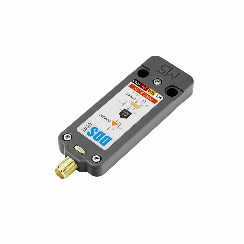
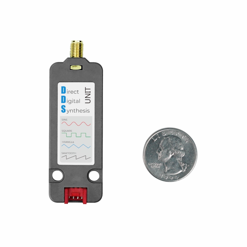
Unit DDS
SKU:U105
Description
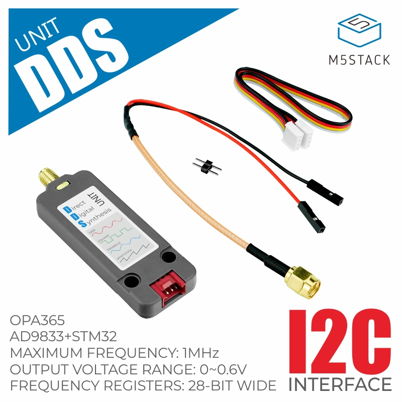
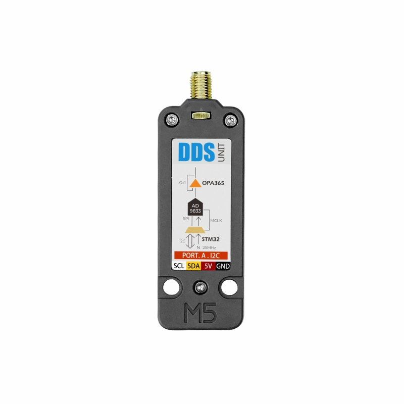
Unit DDS is a signal source Unit. It uses the AD9833 programmable waveform generator + STM32F0 control scheme. It provides an I2C communication interface (addr: 0x31) and operates by configuring registers in practical use. It allows easy control of the signal source to output various waveforms (sine wave, triangle wave, square wave output, sawtooth wave, signal output amplitude 0-0.6V), and to adjust frequency and phase. It also supports sleep strategies to further reduce power consumption when idle. This Unit is suitable for use as a signal source in the electronic circuit prototyping of various test instruments.
Features
- Digitally programmable frequency and phase
- Signal output amplitude 0-0.6V
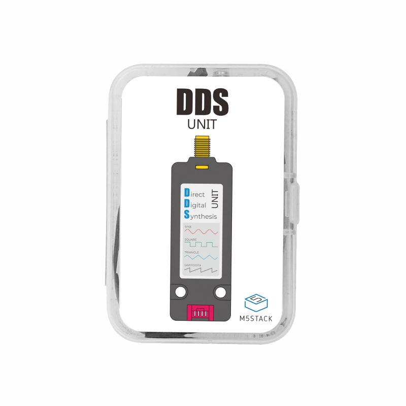
- Sine wave/triangle wave/square wave/sawtooth wave (fixed frequency: 13.6KHz)/DC output
- Output frequency range: 0MHz to 1MHz (10MHz reference clock)
- 28-bit frequency resolution
- 11-bit phase resolution
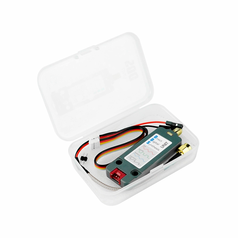
Includes
- 1 x Unit DDS
- 1 x HY2.0-4P Grove cable (20cm)
- 1 x SMA-2.54mm cable
Applications
- Frequency stimulation/waveform generation
- Liquid and gas flow measurement
- Sensor applications: proximity, motion, and defect detection
- Line loss/attenuation
- Testing and medical equipment
- Sweep/clock generator
- Time-domain reflection (TDR) applications
Specifications
| Specification | Parameter |
|---|---|
| MCU | STM32F031G4U6 |
| Communication Interface | I2C @0x31 |
| Supported Waveforms | Sine wave/triangle wave/square wave/sawtooth wave (fixed frequency: 13.6KHz)/DC output |
| Signal Output Amplitude | 0-0.6V |
| Output Frequency Range | 0 MHz to 1MHz (10 MHz reference clock) |
| Frequency Resolution | 28-bit |
| Phase Resolution | 11-bit |
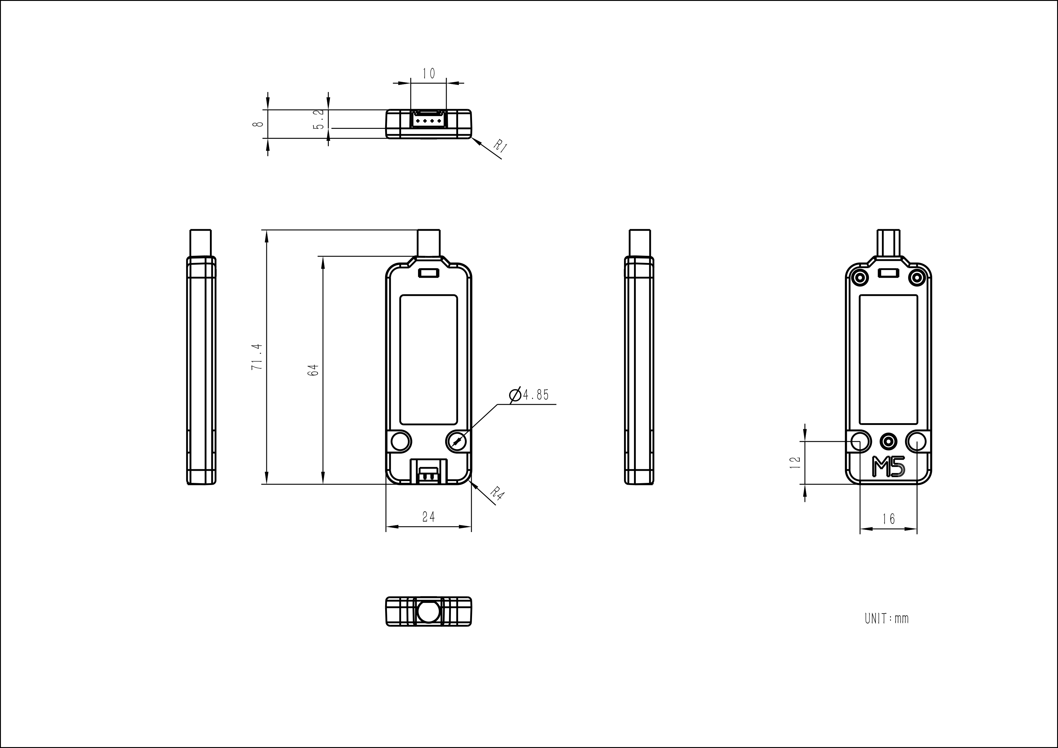
| Product Size | 71.4 x 24.0 x 8.0mm |
| Product Weight | 11.2g |
| Package Size | 88.0 x 60.0 x 21.0mm |
| Gross Weight | 34.0g |
Schematics
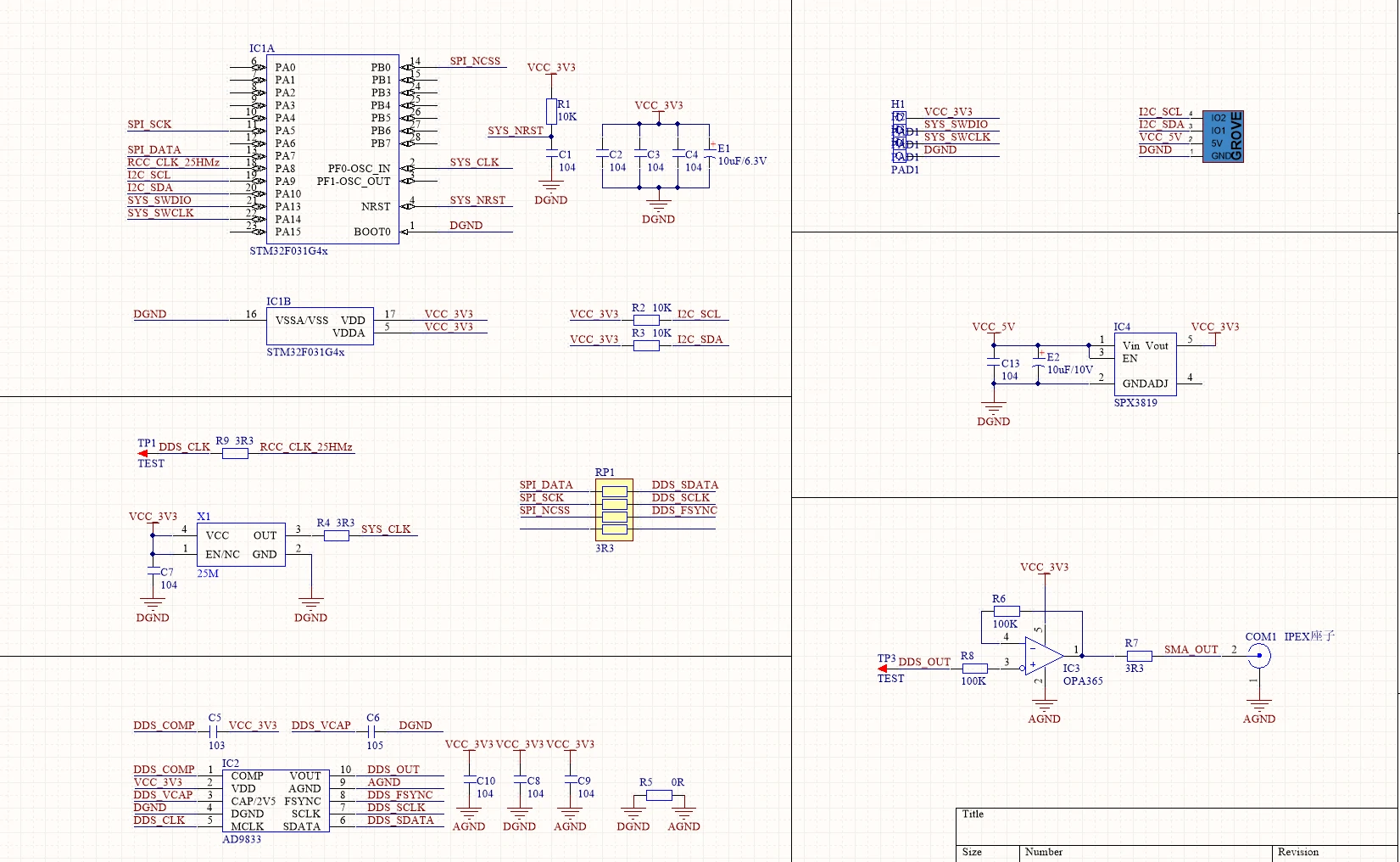
PinMap
Unit DDS
| HY2.0-4P | Black | Red | Yellow | White |
|---|---|---|---|---|
| PORT.A | GND | 5V | SDA | SCL |
Model Size
Datasheets
Softwares
Arduino
UiFlow2
Protocol
- Protocol Type: I2C
- I2C Address: 0x31
Note: When writing to a register, the highest bit needs to be set to 1. Setting mclk to 1 will maintain the last signal amplitude output, and setting DAC to 1 will stop the Unit from outputting.

EasyLoader
| Easyloader | Download Link | Note |
|---|---|---|
| Unit DDS Easyloader | download | / |
Video
Control Unit DDS to output sine wave/triangle wave/square wave/sawtooth wave.