M5Camera-X
SKU:U038
Description
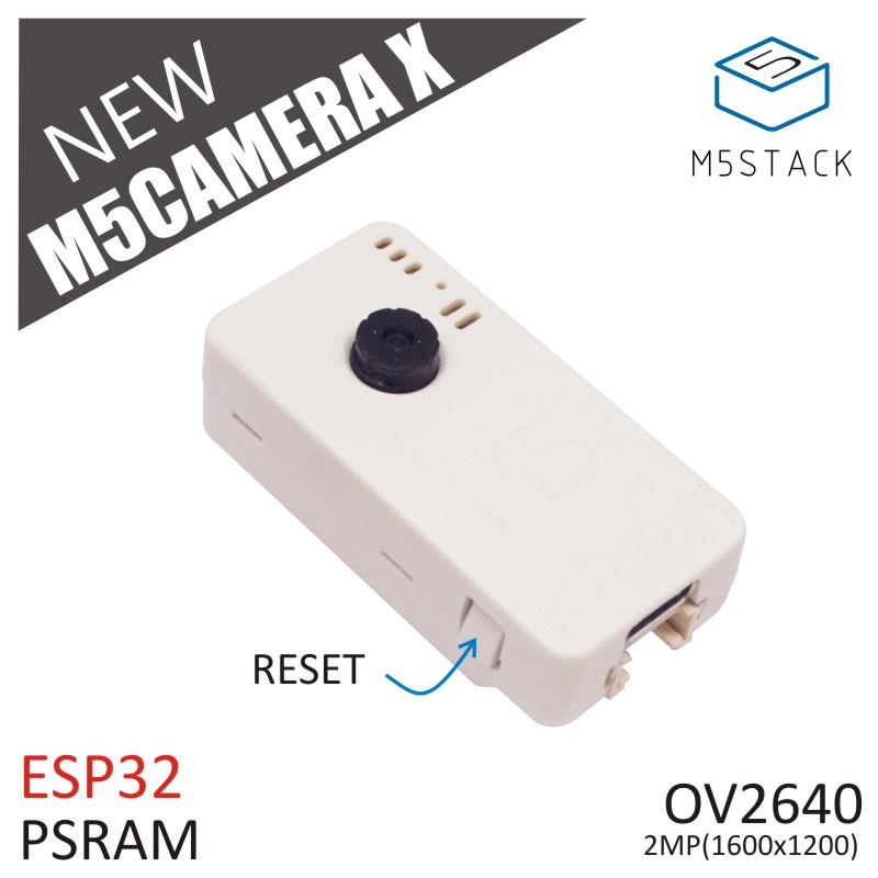
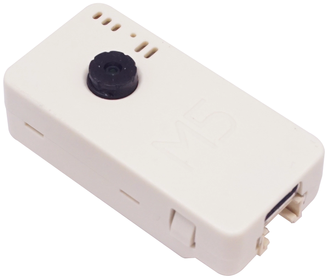
M5Camera-X is an image recognition development board that integrates the ESP32 (4M Flash + 520K RAM + 4M PSRAM) chip and a 2MP camera (OV2640). It supports Wi-Fi image transmission and USB port debugging.
The hardware comes preloaded with firmware, developed using ESP-IDF programming, running a Wi-Fi camera application. The default program outputs an image size of 600 x 800, but you can optimize the program to output larger sizes.
How to use this program?
- Turn on the phone's Wi-Fi and scan to connect to an AP hotspot with a name starting with "m5stack-".
- Open the phone browser and visit 192.168.4.1 to enter the monitoring page and retrieve the live video.
- The video frame rate is about 5-6 frames per second.
Since the module can generate a Wi-Fi hotspot (AP), you can use a phone, PC, or other devices to wirelessly obtain camera images via Wi-Fi, or use the HY2.0-4P interface of the module to get camera images via a wired connection. It currently supports functions such as network camera, color recognition, and face recognition.
Features
- Designed based on ESP32
- Wi-Fi image transmission
- CP2104 USB TTL
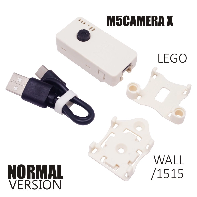
Includes
- 1 x M5Camera-X
- 1 x LEGO-compatible back clip
- 1 x Wall-1515
- 1 x USB Type-C Cable (20cm)
Specifications
| Specification | Parameter |
|---|
| RAM | 4MB |
| Flash | 4M |
| Image Sensor | OV2640 |
| Max Resolution | 2MP |
| Output Format | YUV (422/420) / YCbCr422, 8-bit compressed data, RGB565/555, 8-/10-bit Raw RGB data |
| Field of View | 65° |
| Product Weight | 14g |
| Gross Weight | 38g |
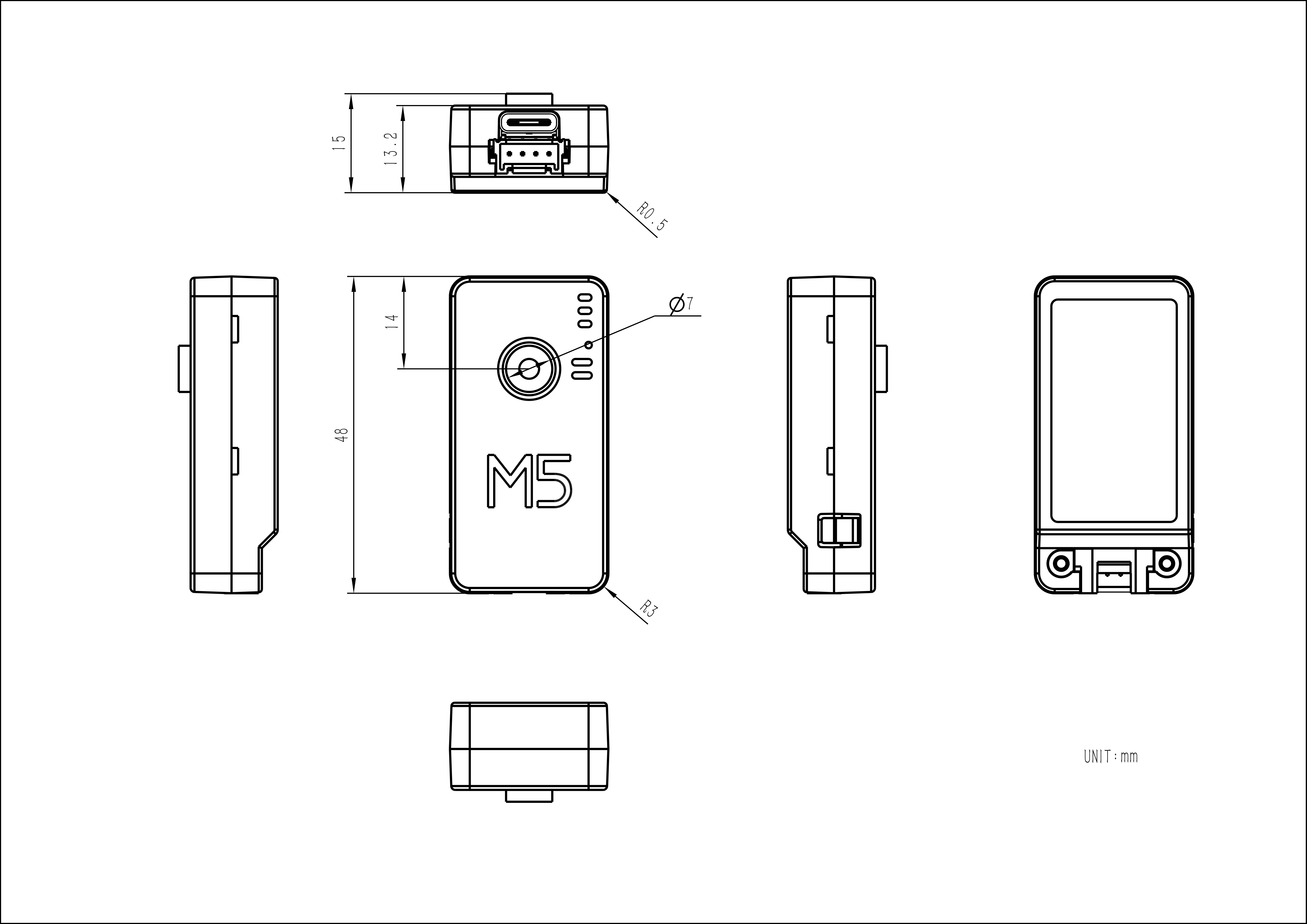
| Product Size | 24 x 48 x 13mm |
| Package Size | 75 x 45 x 30mm |
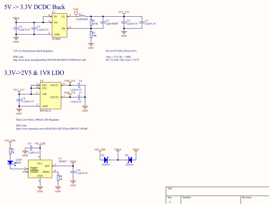
Schematics
Power Circuit
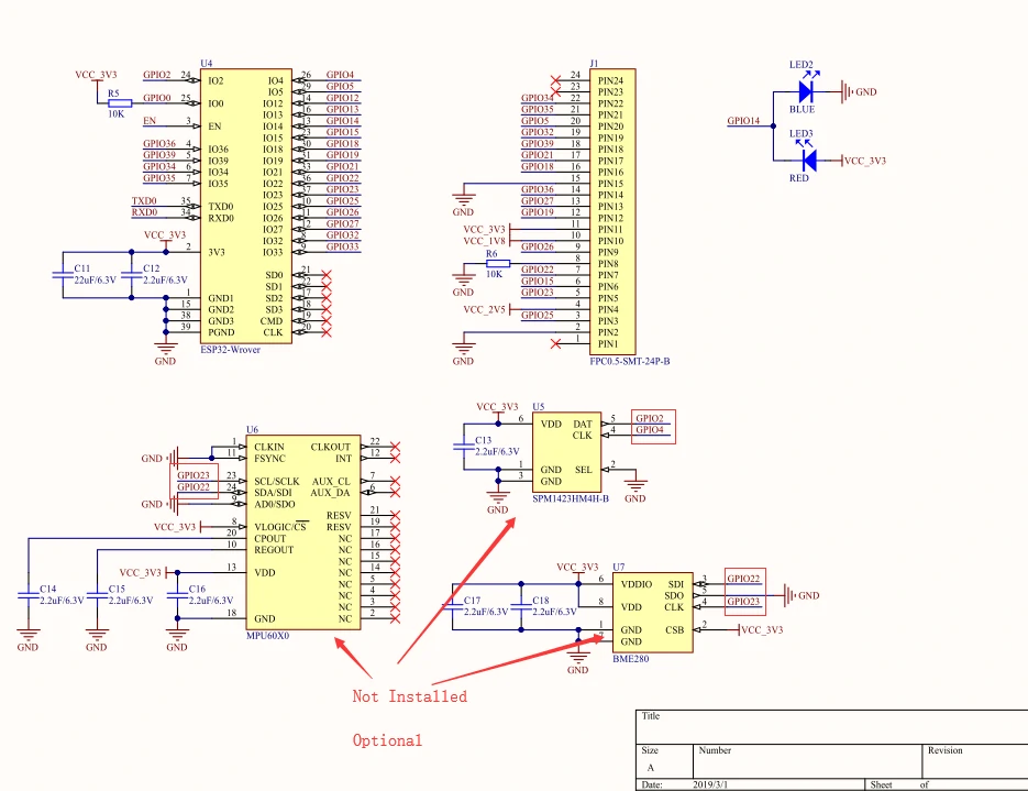
Chip Peripheral Circuit
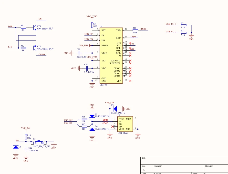
USB to Serial Circuit
PinMap
Camera Driver Chip OV2640 Interface
| Interface | Camera Pin | M5Camera |
|---|
| SCCB Clock | SIOC | G23 |
| SCCB Data | SIOD | G22 |
| System Clock | XCLK | G27 |
| Vertical Sync | VSYNC | G25 |
| Horizontal Reference | HREF | G26 |
| Pixel Clock | PCLK | G21 |
| Pixel Data Bit 0 | D2 | G32 |
| Pixel Data Bit 1 | D3 | G35 |
| Pixel Data Bit 2 | D4 | G34 |
| Pixel Data Bit 3 | D5 | G5 |
| Pixel Data Bit 4 | D6 | G39 |
| Pixel Data Bit 5 | D7 | G18 |
| Pixel Data Bit 6 | D8 | G36 |
| Pixel Data Bit 7 | D9 | G19 |
| Camera Reset | RESET | G15 |
| Camera Power Down | PWDN | See Note1 |
| Power Supply 3.3V | 3V3 | 3V3 |
| Ground | GND | GND |
Note1
The PIN8 (PDWN) pin of the OV2640 chip is the enable pin. On this board, it is connected to ground through a 12KΩ pull-down resistor to enable and enter working mode. When the PIN8 (PDWN) pin is pulled high, it will enter Camera Power Down mode.
HY2.0-4P Interface
| HY2.0-4P | M5Camera |
|---|
| SCL | G13 |
| SDA | G4 |
| 5V | 5V |
| GND | GND |
LED Interface
The following are PCB reserved interfaces, without actual soldered components.
BME280 Interface
| BME280 | M5Camera |
|---|
| SCL | G23 |
| SDA | G22 |
MPU6050 Interface
| MPU6050 | M5Camera |
|---|
| SCL | G23 |
| SDA | G22 |
MIC (SPM1423) Interface
| MIC (SPM1423) | M5Camera |
|---|
| CLK | G4 |
| DATA | G2 |
Model Size
Datasheets
Softwares
Arduino
ESP-IDF
Easyloader
| Easyloader | Download | Note |
|---|
| M5Camera-X AP Firmware Easyloader | download | / |
Product Comparison