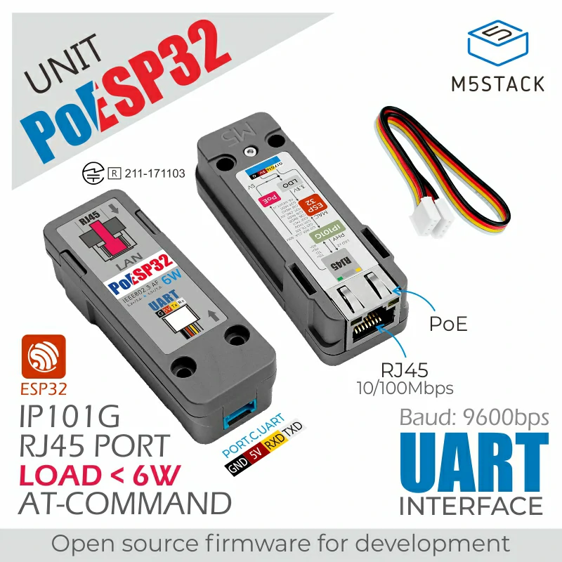
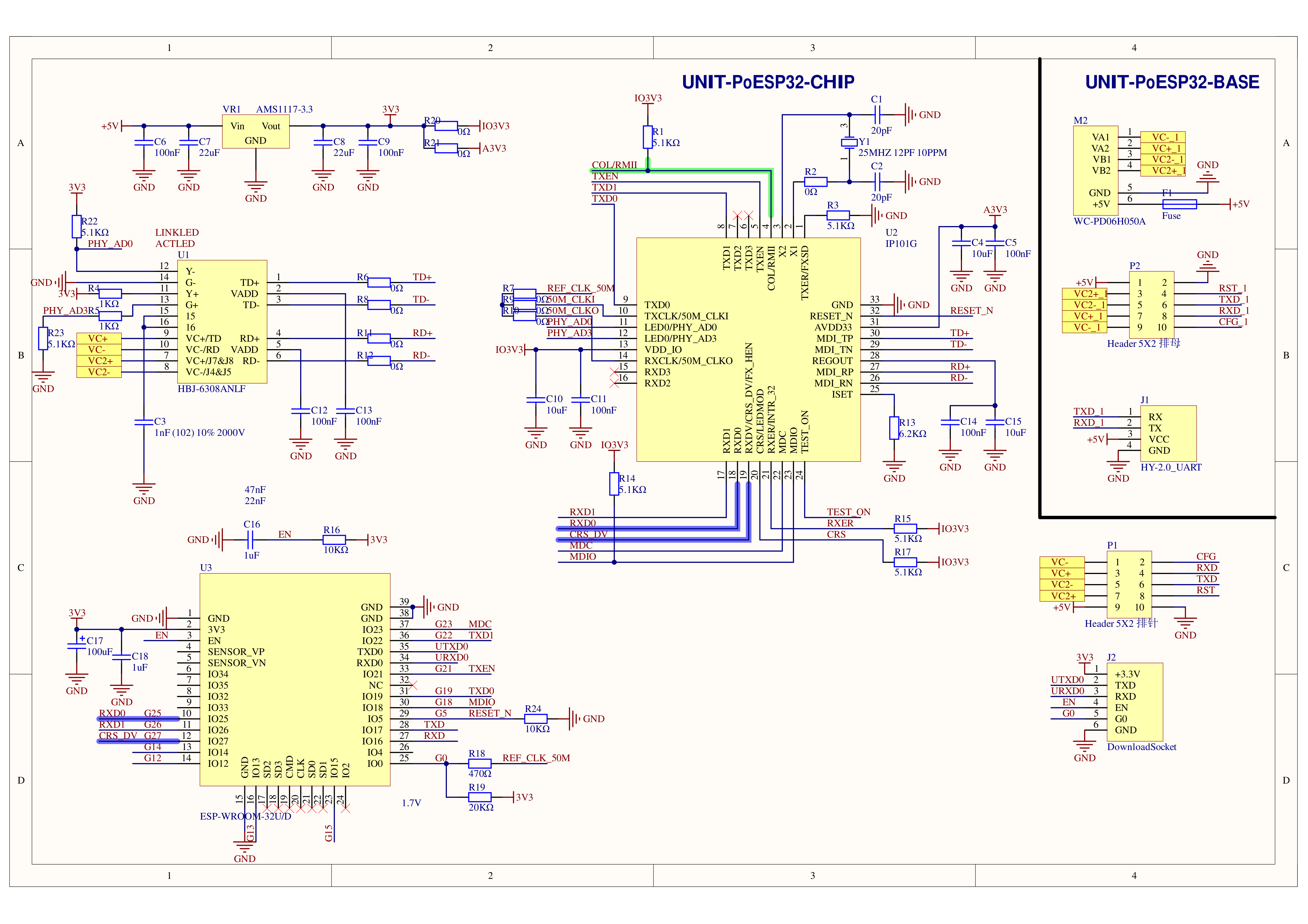
Unit PoESP32 is an ESP32 Ethernet controller integrated with PoE (Power Over Ethernet) functionality. It adopts the ESP32 built-in MAC + IP101G physical layer transceiver solution. The module comes preloaded with ESP-AT firmware, supporting various protocol stack control commands such as TCP, MQTT, and HTTP. Through serial communication, simple AT commands can be used to achieve server connection, data communication, and remote control functions. With PoE power supply, it not only saves unnecessary power cables but also provides a certain load capacity for your devices. The module reserves secondary development interfaces, and with the rich examples and protocol stack support in the ESP32 development platform, it can quickly achieve customized functions according to your usage scenarios.
Features
Embedded ESP32 main control core
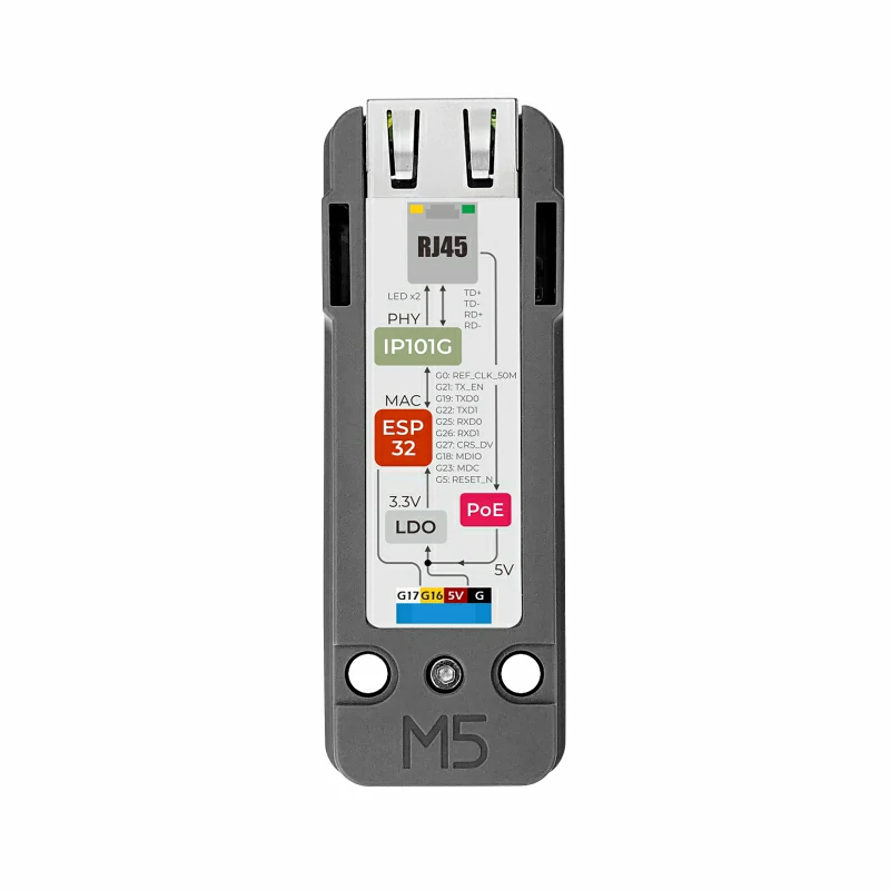
PHY solution:
Transceiver model: IP101G
IEEE 802.3/802.3u standard
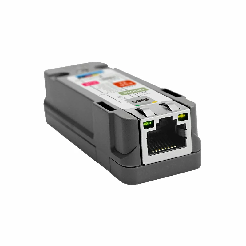
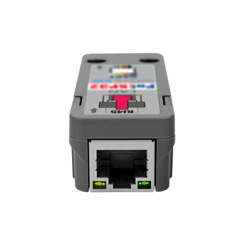
Ethernet interface:
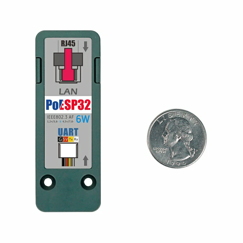
PoE standard: PoE IEEE802.3 AF / Supports a maximum load power of 6W
RJ45 port 10/100Mbps
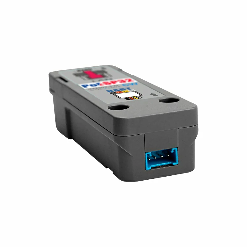
Communication/Download interface:
Default firmware: ESP-AT / Supports secondary development for TCP Client/HTTP/CoAP and other protocol stacks
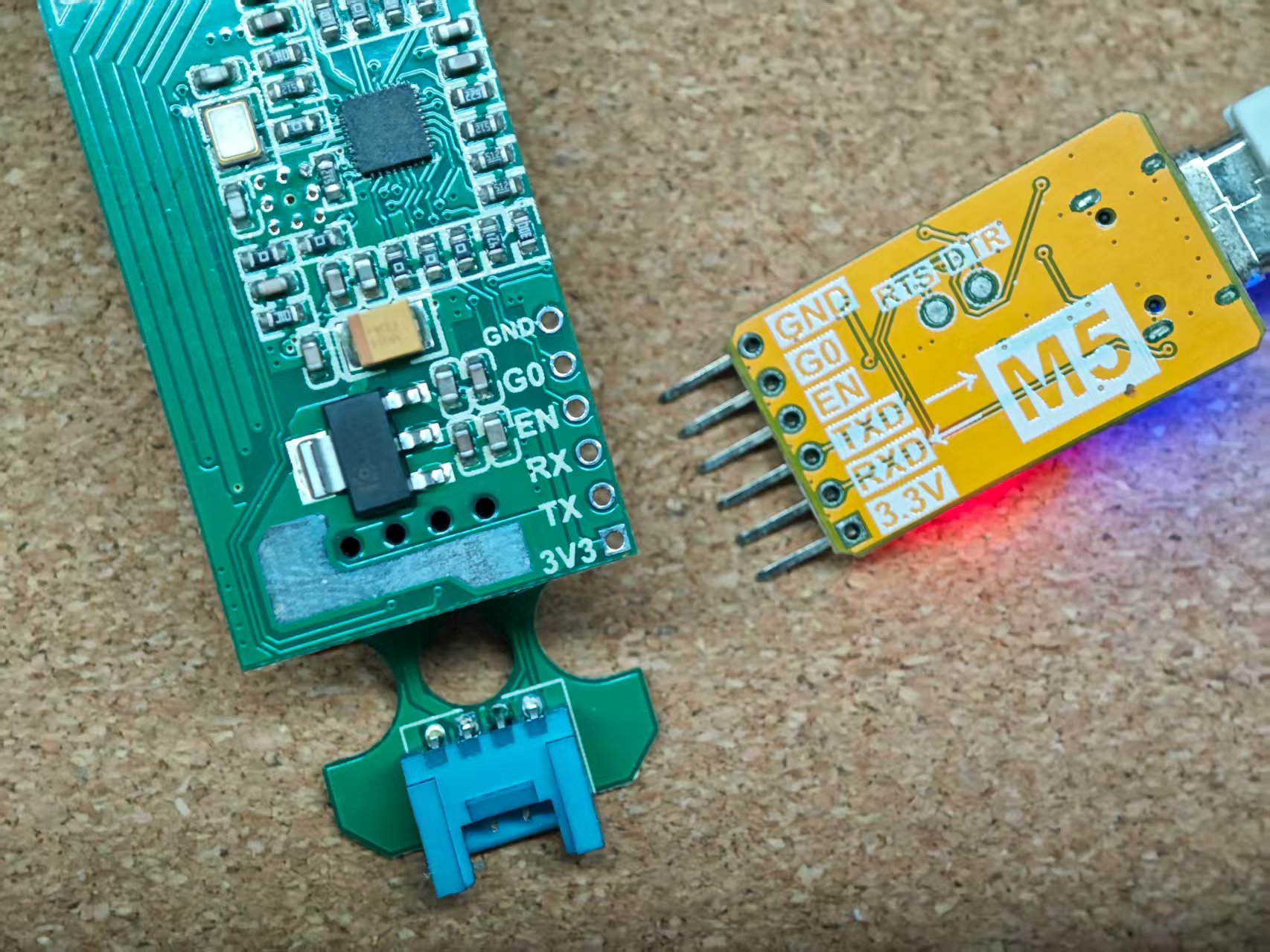
Programmable / Supports secondary development, with reserved program download interface
Power supply methods:
HY2.0-4P interface 5V power supply
PoE power supply (PoE IEEE802.3 AF)
Development methods:
AT commands, UART: 9600bps default
Development platforms: UIFlow (coming soon), Arduino, ESP-IDF
Includes
1 x Unit PoESP32
1 x HY2.0-4P Grove cable (20cm)
Applications
Ethernet controller
Data communication and remote control
Specifications
Specification
Parameter
ESP32-WROOM-32U
240MHz dual core, 600 DMIPS, 520KB SRAM (no 3D antenna, no WiFi & BLE wireless)
Flash
4MB
PHY
IP101G: IEEE 802.3/802.3u
MAC-PHY interface type
RMII
PoE standard
PoE IEEE802.3 AF standard / Maximum power 6W / Supply voltage DC 37-57V
Ethernet interface spec
RJ45 10/100Mbps
Reserved interfaces
1x HY2.0-4P interface, 1x program download interface
Communication interface
UART 9600bps 8N1 AT command control
Communication logic level
3.3V
Net weight
26.2g
Gross weight
32.8g
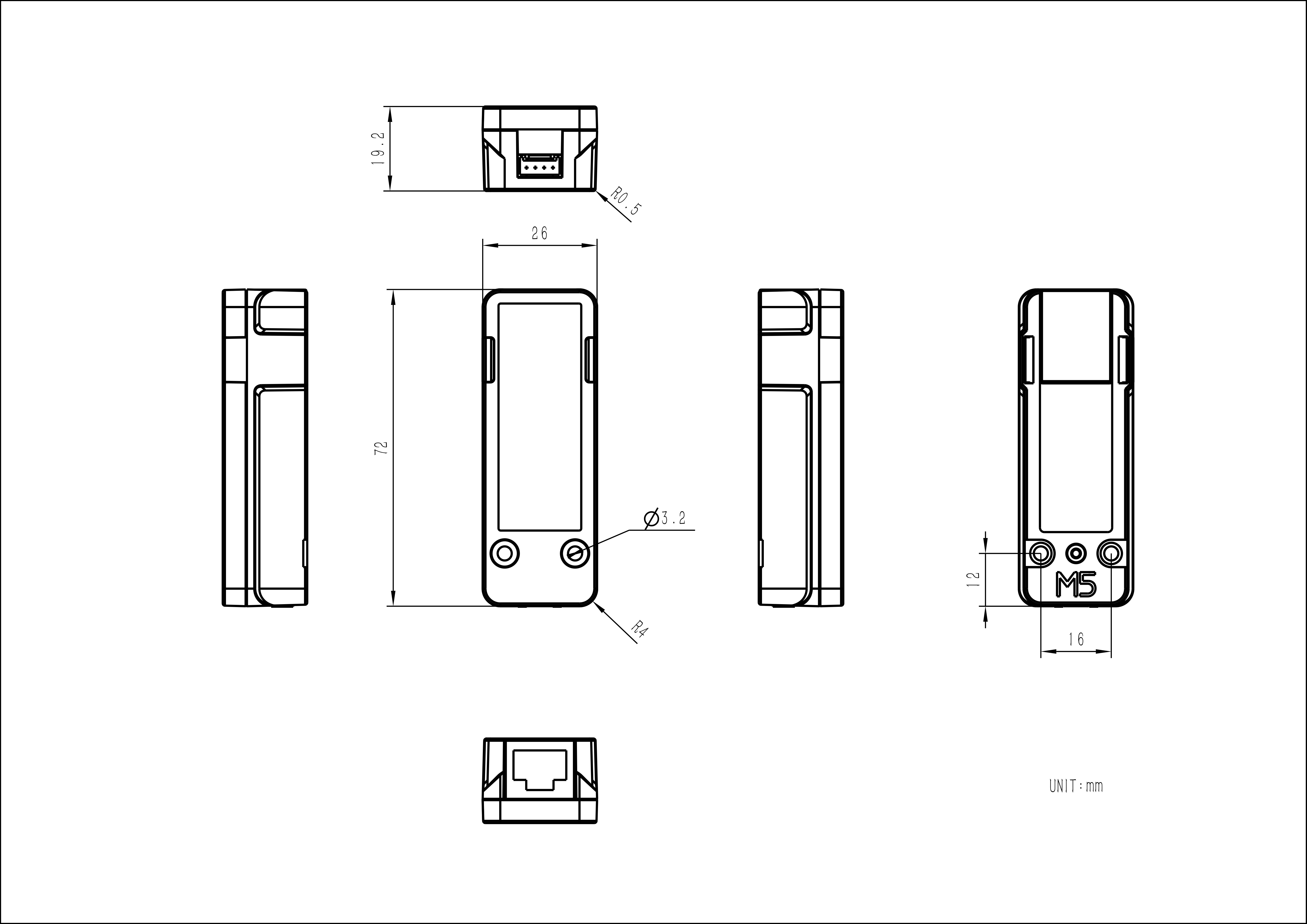
Product Size
72 x 26 x 19.2mm
Package Size
75 x 36 x 20.5mm
Learn
Program Download
If secondary development is required, you can remove the device casing and connect the ESP32 Downloader through the reserved secondary development interface for program downloading.