pdf-icon

Unit RFID-UHF

SKU:U107
Description

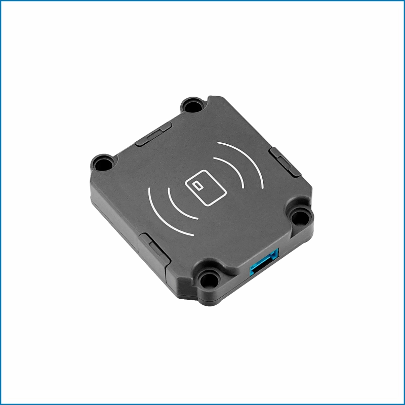
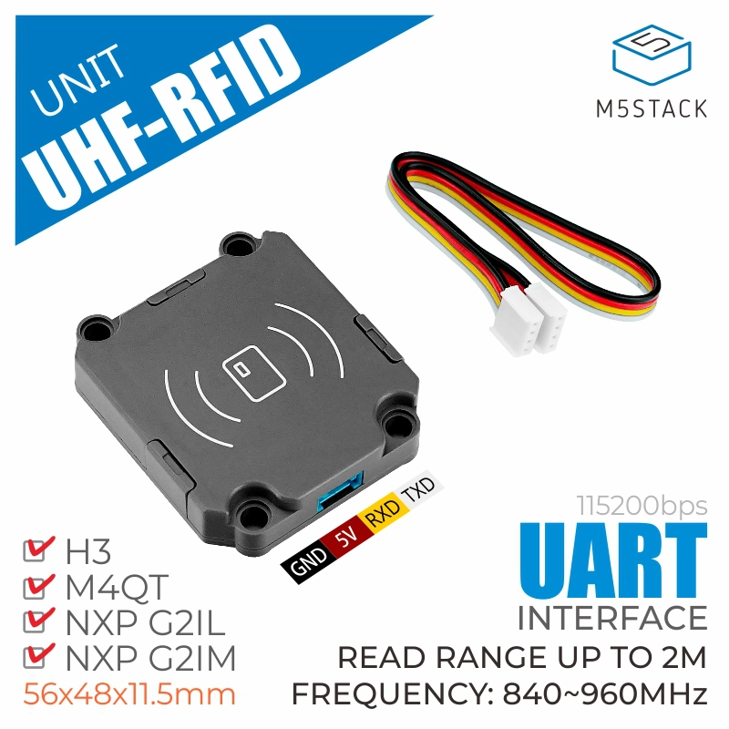
UHF-RFID is an ultra-high frequency (UHF) embedded wireless radio frequency reader module. The JRD-4035 module solution with built-in ceramic antenna completely eliminates the technical uncertainty that ordinary uhf rfid reader modules need to be equipped with additional antennas for users. Optimize the RF design to realize the low power consumption and high performance of the module, and the transmission power of 100mW can reach the effective distance of more than 1.5M. Use serial communication interface, cooperate with built-in encapsulated AT command set, realize plug and play, provide good development and use experience. It is suitable for application scenarios such as warehousing logistics management and smart retail, and meets the application requirements of monitoring and reading multiple product tags.

Features

  • Detection distance: up to 2M
  • Working spectrum range: 840-960MHz
  • Air interface protocol:
    • EPCglobal UHF Class 1 Gen 2
    • ISO 18000-6C
  • UART communication interface (baud rate: 115200bps)
  • The buffer area can hold up to 200 tags
  • Tag recognition is sensitive and stable

Includes

  • 1x UHF-RFID
  • 1x HY2.0 cable (20CM)

Applications

  • Warehouse logistics pallet management
  • Vehicle management
  • Smart retail

Specifications

Specifications Parameters
Air interface protocol EPCglobal UHF Class 1 Gen 2 / ISO 18000-6C
Work area support US, Canada and other regions following U.S.FCC. Europe and other regions following ETSI EN 302 208, Mainland China, Japan, Korea, Malaysia, Taiwan
Working spectrum range 840-960MHz
Output power range 18-26 dBm
Tag cache area 200 tags
Communication protocol UART (Baud rate: 115200bps)
Net weight 41g
Gross weight 58.8g
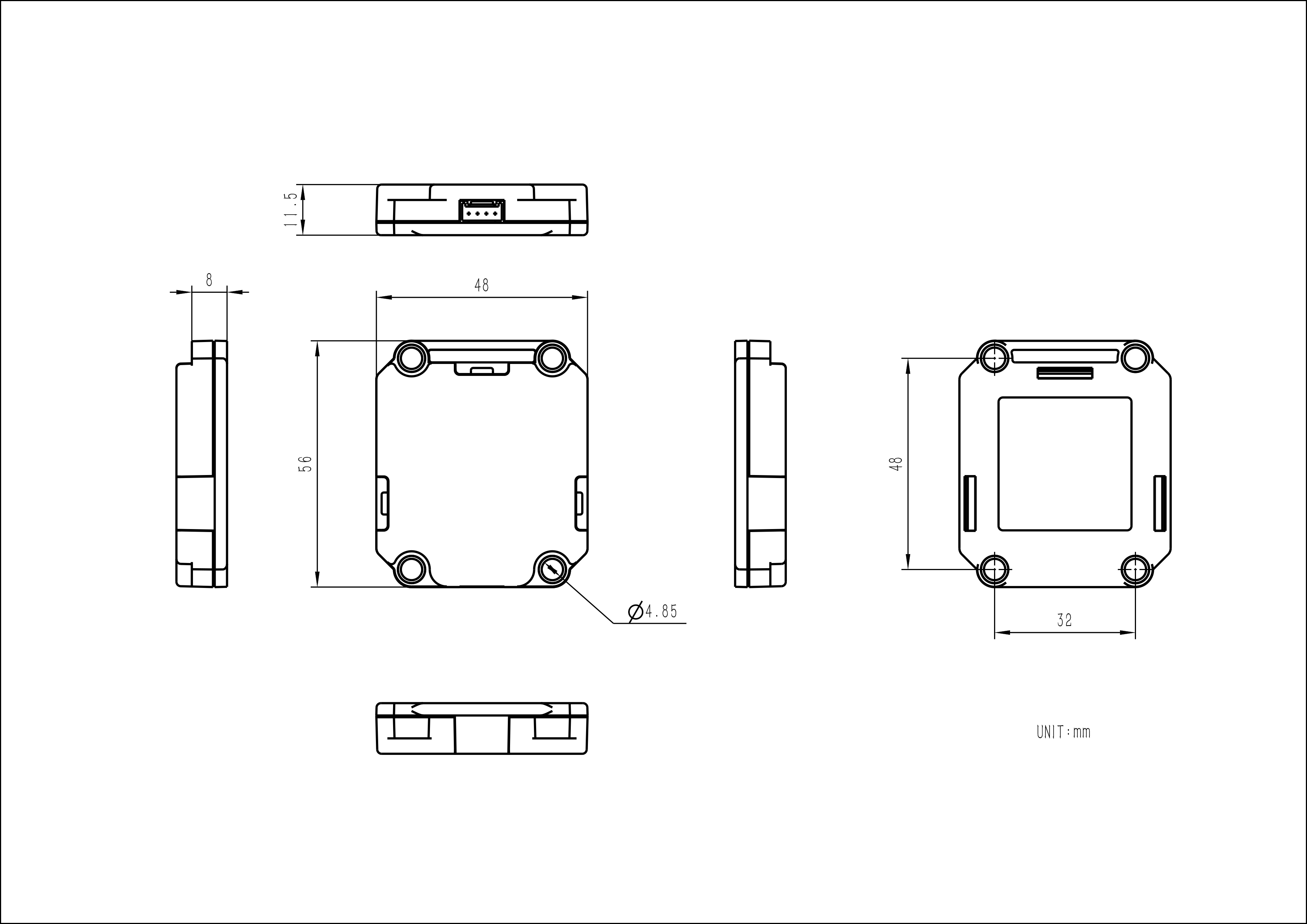
Product size 56*48*11.5mm
Package size 88*61*21mm
Shell material Plastic (PC )

EasyLoader

Pin mapping

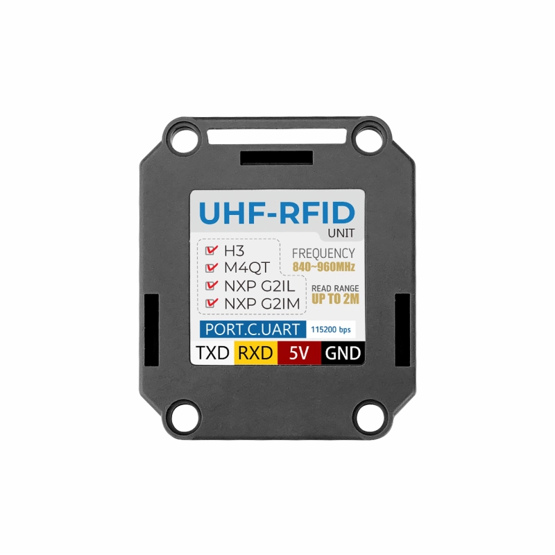
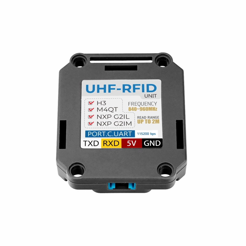
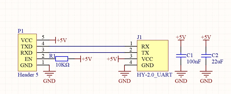
When connecting UHF-RFID Unit to PortC, the pin mapping is as follows

M5Core(PORT C) GPIO16 GPIO17 5V GND
UHF-RFID Unit TXD RXD 5V GND

Schematics

Caution:
Please set the appropriate frequency to comply with your local laws and regulations.

Datasheetss

Softwares

Arduino


//0. Hardware version
BB 00 03 00 01 00 04 7E

//1. Software version
BB 00 03 00 01 01 05 7E

//2.manufacturers
BB 00 03 00 01 02 06 7E

//3. Single polling instruction
BB 00 22 00 00 22 7E

//4. Multiple polling instructions
BB 00 27 00 03 22 27 10 83 7E

//5. Stop multiple polling instructions
BB 00 28 00 00 28 7E

//6. Set the SELECT parameter instruction
BB 00 0C 00 13 01 00 00 00 20 60 00 30 75 1F EB 70 5C 59 04 E3 D5 0D 70 AD 7E

//7. Get the SELECT parameter
BB 00 0B 00 00 0B 7E

//8. Set the SELECT mode
BB 00 12 00 01 01 14 7E

//9. Read label data storage area
BB 00 39 00 09 00 00 FF FF 03 00 00 00 02 45 7E

//10. Write the label data store
BB 00 49 00 0D 00 00 FF FF 03 00 00 00 02 12 34 56 78 6D 7E

//11. Lock the LOCK label data store
BB 00 82 00 07 00 00 FF FF 02 00 80 09 7E,

//12. Inactivate the kill tag
BB 00 65 00 04 00 00 FF FF 67 7E

//13. Set communication baud rate
BB 00 11 00 02 00 C0 D3 7E

//14. Get parameters related to the Query command
BB 00 0D 00 00 0D 7E

//15. Set the Query parameter
BB 00 0E 00 02 10 20 40 7E

//16. Set up work area
BB 00 07 00 01 01 09 7E

//17. Acquire work locations
BB 00 08 00 00 08 7E

//18. Set up working channel
BB 00 AB 00 01 01 AC 7E

//19. Get the working channel
BB 00 AA 00 00 AA 7E

//20. Set to automatic frequency hopping mode
BB 00 AD 00 01 FF AD 7E

//21. Insert the working channel
BB 00 A9 00 06 05 01 02 03 04 05 C3 7E

//22. Acquire transmitting power
BB 00 B7 00 00 B7 7E

//23. Set the transmitting power
BB 00 B6 00 02 07 D0 8F 7E

//24. Set up transmitting continuous carrier
BB 00 B0 00 01 FF B0 7E

//25. Gets the receiving demodulator parameters
BB 00 F1 00 00 F1 7E

//26. Set the receiving demodulator parameters
BB 00 F0 00 04 03 06 01 B0 AE 7E

//27. Test the RF input block signal
BB 00 F2 00 00 F2 7E

//28. Test the RSSI signal at the RF input
BB 00 F3 00 00 F3 7E

//30. Module hibernation
00 BB 00 17 00 00 17 7E

//31. Idle hibernation time of module
BB 00 1D 00 01 02 20 7E

//32. The IDLE mode
BB 00 04 00 03 01 01 03 0C 7E

//33.NXP G2X label supports ReadProtect/Reset ReadProtect command
BB 00 E1 00 05 00 00 FF FF 00 E4 7E

//34. The NXP G2X label supports the CHANGE EAS directive
BB 00 E3 00 05 00 00 FF FF 01 E7 7E

//35. The NXP G2X tag supports the EAS_ALARM directive
BB 00 E4 00 00 E4 7E

//36.NXP G2X label 16bits config-word
BB 00 E0 00 06 00 00 FF FF 00 00 E4 7E

//37.Impinj Monza 4 Qt tags support Qt instructions
BB 00 E5 00 08 00 00 FF FF 01 01 40 00 2D 7E

//38.The BlockPermalock directive permanently locks blocks of a user's Block
BB 00 D3 00 0B 00 00 FF FF 01 03 00 00 01 07 00 E8 7E

Model Size

Video