

Atom DTU LoRaWAN915
SKU: K061
Tutorial

Description
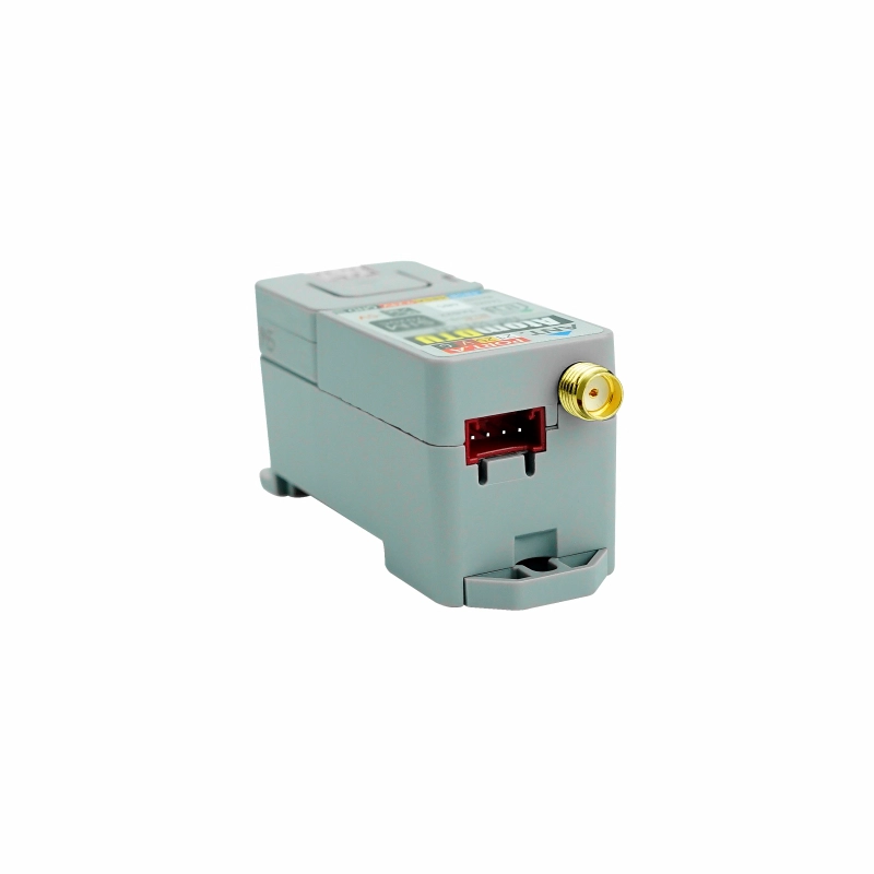
Atom DTU LoRaWAN915 is a programmable data transmission unit (DTU) suitable for the 915MHz frequency LoRaWAN. The module adopts the ASR6501 solution, supporting long-distance communication while featuring ultra-low power consumption and high sensitivity. The module integrates the LoRaWAN protocol stack and uses a serial communication interface (controlled by AT commands). It can be used as a collection node to connect to gateways in large numbers for data collection and management. The integrated SMA external antenna interface enhances the communication quality and signal stability of the device. Unlike general DTUs that only have data transmission functions, the Atom DTU LoRaWAN915 series adopts a more open architecture design. The Atom-Lite controller can modify the program according to actual business needs, and the device reserves multiple interfaces (RS485, I2C, custom interfaces) for user expansion, facilitating the quick connection of sensors and actuators. It comes with a rail clamping structure, perfectly embedding into various industrial control sites.
Features
- ASR6501
- Supports US915
- Serial communication: UART 115200bps (AT commands)
- Strong anti-interference capability, able to work normally in complex interference environments
- RS485 communication interface (with 12V input interface, internally integrated DC-DC step-down to 5V)
- Modbus Master/slave
- Strong signal access capability
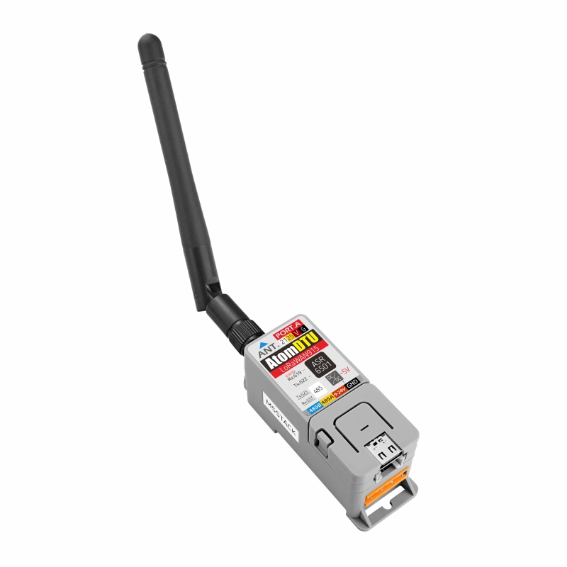
- External antenna: SMA antenna interface
- Grove expansion interface:
- I2C x1
- Custom x1
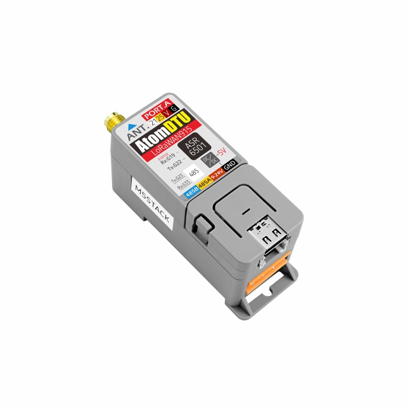
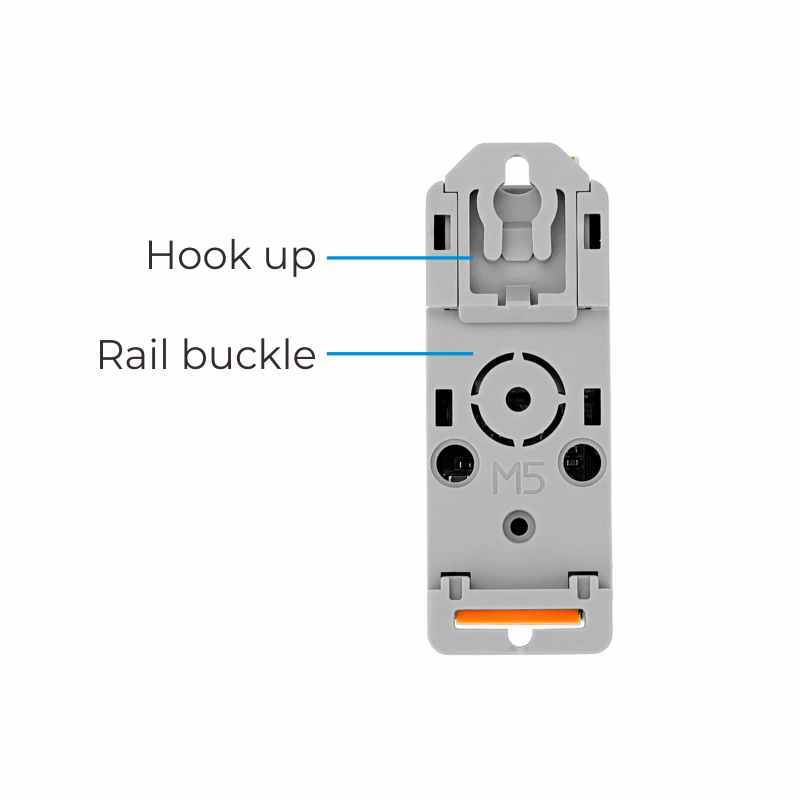
- Comes with rail clamping
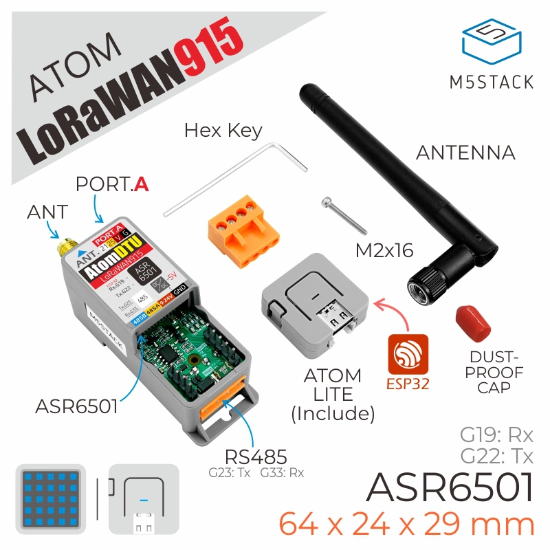
Includes
- 1 x Atom-Lite
- 1 x Atomic DTU LoRaWAN915 Base
- 1 x SMA antenna
- 1 x SMA red cap
- 1 x M2 hex wrench
- 1 x M2x16 screw
- 1 x HT3.96-4P terminal
Applications
- Automatic remote meter reading
- Smart transportation and smart parking
- Remote irrigation and environmental monitoring
Specifications
| Specification | Parameter |
|---|---|
| Communication chip | ASR6501 |
| Operating frequency | 915MHz |
| LoRaWAN version | v1.0.1 |
| Minimum receive sensitivity | -137dBm (SF=12/BW=125KHz) |
| Maximum transmit power | +21dBm |
| Communication method | UART 115200bps |
| Product Size | 64 x 24 x 29mm |
| Product weight | 32g |
| Package Size | 91 x 42 x 24.5mm |
| Gross weight | 40g |
Learn
This product supports the
US915 frequency band by default and does not support AU915.Supported US915 Countries and Regions
Argentina/Canada/Chile/Colombia/Ecuador/Greece Guatemala/Jamaica/Mexico/Nicaragua/Panama/United States/Uruguay
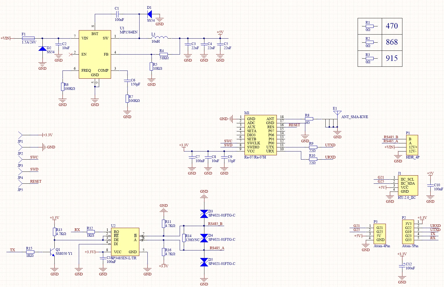
Schematics
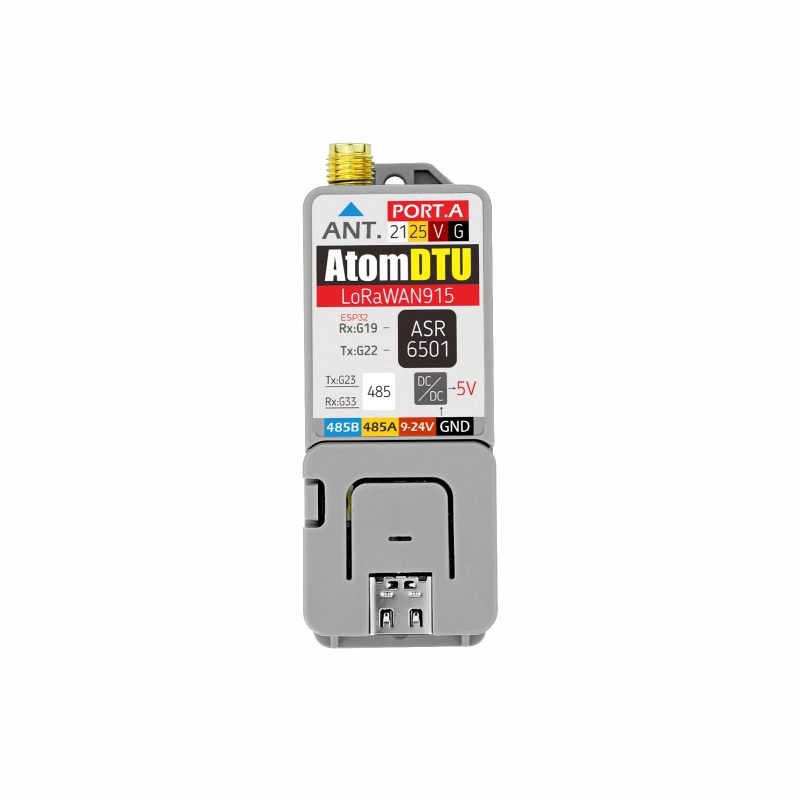
PinMap
| PIN | LEFT | RIGHT | PIN |
|---|---|---|---|
| 1 | 3V3 | ||
| PORT.A | 2 | 3 | UART_RX |
| PORT.A | 4 | 5 | UART_TX |
| 5V | 6 | 7 | RS485_RX |
| GND | 8 | 9 | RS485_TX |
- LoRaWAN915
| Atom | G22(TX) | G19(RX) | 5V | GND |
|---|---|---|---|---|
| LoRaWAN915 | RX | TX | VIN | GND |
- RS485
| Atom | G23 | G33 | 5V | GND |
|---|---|---|---|---|
| RS485 | TX | RX | VIN | GND |
- I2C
| Atom | G25 | G21 | 5V | GND |
|---|---|---|---|---|
| I2C | SDA | SCL | VIN | GND |
Datasheets
Softwares
Arduino
- Examples
- Libraries