M5GO-Lite
SKU:K022
Description
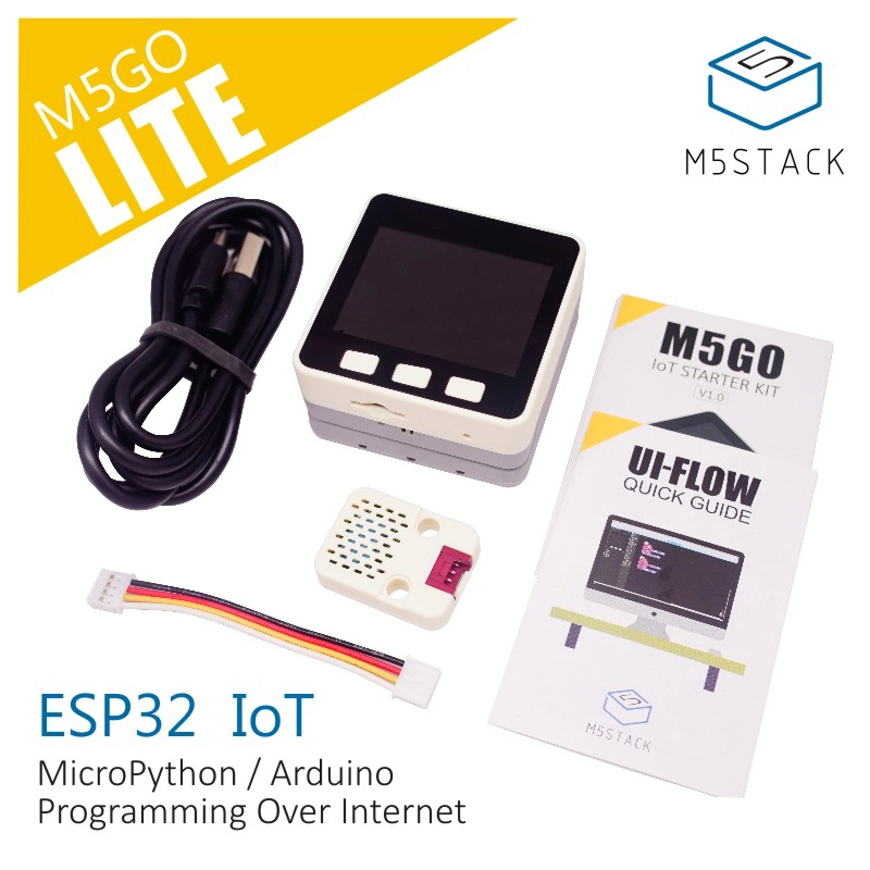
M5GO-Lite is a lightweight STEM education kit in the M5Stack development kit series. M5GO Lite provides 1 ENV Unit (for environment temperature, humidity, and atmospheric pressure detection). Compared with the "M5GO IoT Kit", it reduces the number of Units and accessories in exchange for certain flexibility in pairing, making it a good choice for users who wish to purchase other Units themselves or conduct small-scale STEM courses.
It offers an online version of the WebIDE UIFlow programming platform, enabling students to experience the power of IoT by pushing programs over the network. It supports multiple programming methods, helping students gradually progress from graphical programming to understanding actual code.
As a kit designed specifically for STEM education, M5GO aims to allow students to gain knowledge while having fun, and to enjoy the sense of achievement from turning their ideas step-by-step into reality. It empowers students to freely explore the world of engineering, create their own IoT products, and integrate exciting ideas into real life.
Tutorial
This tutorial will introduce you to controlling the M5GO device via the UIFlow graphical programming platform
This tutorial will introduce you to controlling the M5GO device via the UiFlow2 graphical programming platform
This tutorial will introduce you to programming and controlling the M5GO device via the Arduino IDE
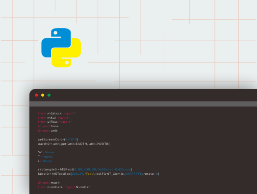
This tutorial will introduce you to programming and controlling the M5GO device via Micropython
Features
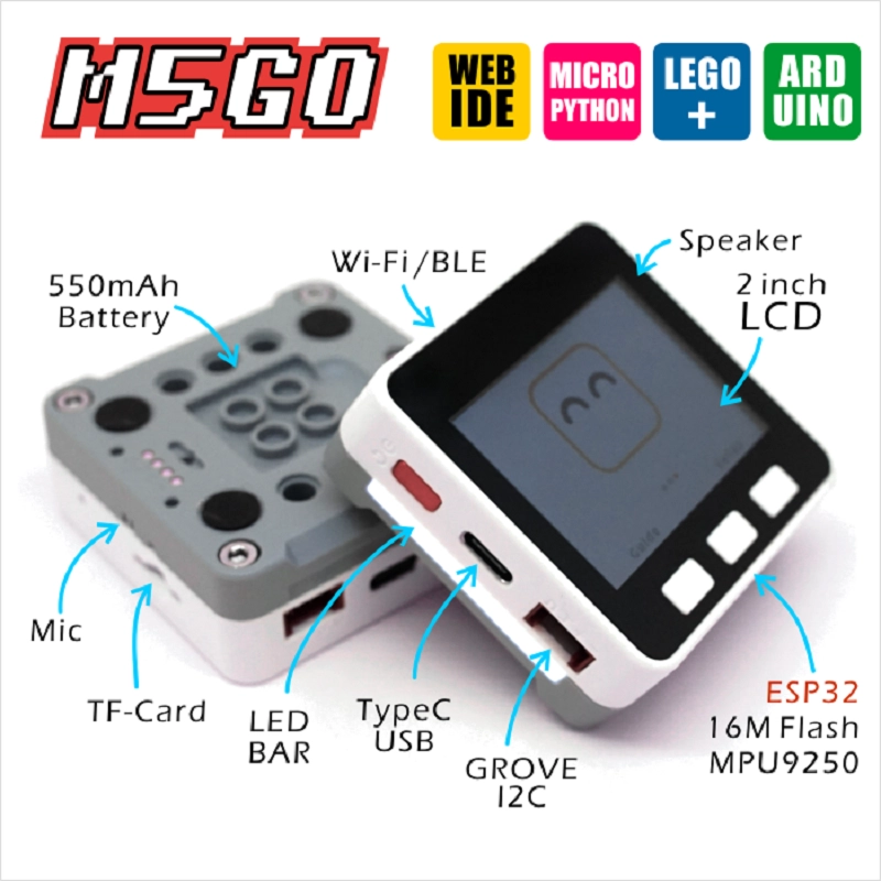
- Based on ESP32 development
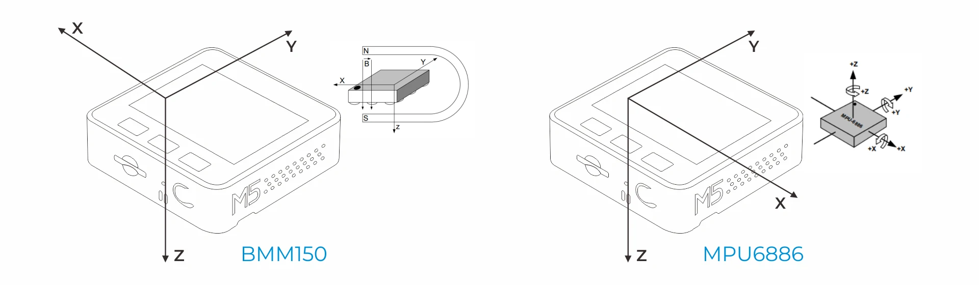
- Integrated 3-axis accelerometer, 3-axis gyroscope, and 3-axis magnetometer
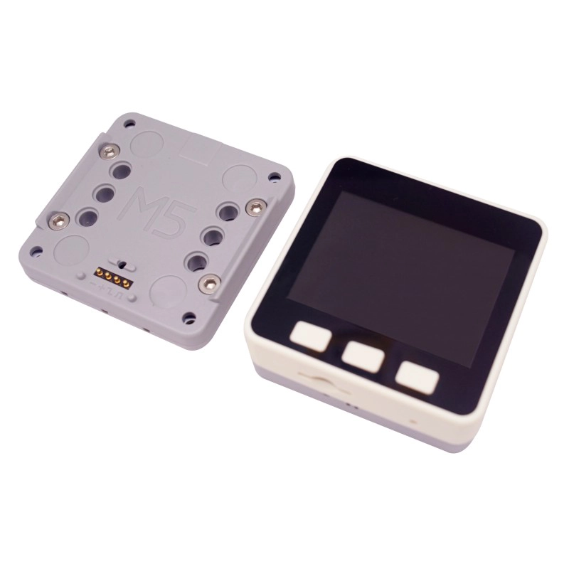
- Built-in speaker, buttons, LCD screen, power/reset button
- TF card slot (supports up to 16GB expansion)
- Expandable pins and interfaces
- M5-Bus bus socket
- Built-in lithium battery
- Magnetic rear charging design
- Development Platform
- UiFlow1
- UiFlow2
- Arduino IDE
- ESP-IDF
- PlatformIO
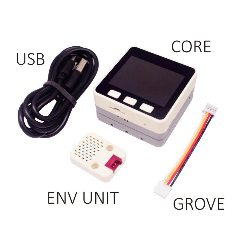
Includes
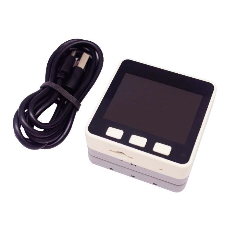
- 1 x M5GO
- 1 x ENV Unit
- 1 x GROVE Cable
- 1 x USB Type-C Cable (20cm)
- 1 x User Manual
Applications
- IoT controller
- STEM education
- DIY projects
- Smart home devices
Specifications
| Specification | Parameter |
|---|
| SoC | ESP32-D0WDQ6-V3@dual-core processor, 240MHz main frequency |
| DMIPS | 600 |
| SRAM | 520KB |
| Flash | 16MB |
| Wi-Fi | 2.4 GHz Wi-Fi |
| Input Voltage | 5V@500mA |
| Host Interface | USB Type-C x 1, GROVE (I2C+I/O+UART) x 1 |
| IPS Display | 2 inch, 320x240 Colorful TFT LCD, ILI9342C, max brightness 853nit |
| Speaker | 1W-0928 |
| Microphone | MEMS Analog BSE3729 Microphone |
| Buttons | Custom buttons x 3 |
| LED | SK6812 3535 RGB LED x 10 |
| MEMS | BMM150 + MPU6886 |
| Antenna | 2.4G 3D antenna |
| Base Interface | PORT.A (I2C), PORT.B (GPIO), PORT.C (UART) |
| Battery | 500mAh@3.7V, inside vb |
| Operating Temperature | 0 ~ 60°C |
| Case Material | Plastic (PC) |
| Product Size | 54.0 x 54.0 x 21.0mm |
| Product Weight | 56.4g |
| Package Size | 105.0 x 65.0 x 40.0mm |
| Gross Weight | 159.0g |
Learn
BMM150 Magnetic Field Interference
Products with magnets may interfere with the BMM150 magnetic field sensor, causing abnormal readings. When using M5 host devices containing magnets, remove the magnets and avoid placing the BMM150 sensor near strong magnetic fields.
Power On/Off
Power On/Off Operation
Power on: Click the red power button on the left
Power off: Quickly double-click the red power button on the left
Note: By default, it is not possible to power off when USB powered
Schematics
PinMap
LCD & TF card
LCD: 320x240
TF card Maximum size 16GB
| ESP32-D0WDQ6-V3 | G23 | G19 | G18 | G14 | G27 | G33 | G32 | G4 |
|---|
| ILI9342C | MOSI/MISO | / | CLK | CS | DC | RST | BL | |
| TF Card | MOSI | MISO | CLK | | | | | CS |
| ESP32-D0WDQ6-V3 | G39 | G38 | G37 | G25 |
|---|
| Button Pin | BUTTON A | BUTTON B | BUTTON C | |
| Speaker | | | | Speaker Pin |
GROVE Port A & IP5306
We've used a customized I2C version of IP5306 in power management.
Its I2C address is 0x75. Click here to check its datasheet.
| ESP32-D0WDQ6-V3 | G22 | G21 | 5V | GND |
|---|
| GROVE A | SCL | SDA | 5V | GND |
| IP5306 | SCL | SDA | 5V | GND |
IP5306 charging/discharging, Voltage parameter
| charging | discharging |
|---|
| 0.00 ~ 3.40V -> 0% | 4.20 ~ 4.07V -> 100% |
| 3.40 ~ 3.61V -> 25% | 4.07 ~ 3.81V -> 75% |
| 3.61 ~ 3.88V -> 50% | 3.81 ~ 3.55V -> 50% |
| 3.88 ~ 4.12V -> 75% | 3.55 ~ 3.33V -> 25% |
| 4.12 ~ / -> 100% | 3.33 ~ 0.00V -> 0% |
6-Axis MotionTracking Sensor MPU6886
MPU6886 I2C address 0x68
| ESP32-D0WDQ6-V3 | G22 | G21 | 5V | GND |
|---|
| MPU6886 | SCL | SDA | 5V | GND |
3-Axis Geomagnetic Sensor BMM150
BMM150 I2C address 0x10
| ESP32-D0WDQ6-V3 | G22 | G21 | 5V | GND |
|---|
| BMM150 | SCL | SDA | 5V | GND |
M5GO Base
Click to view details
Peripheral PinMap
LCD Screen & TF Card
_LCD Resolution: 320x240_
TF card supports up to 16GB
| ESP32-D0WDQ6-V3 | G23 | G19 | G18 | G14 | G27 | G33 | G32 | G4 |
|---|
| ILI9342C | MOSI/MISO | / | CLK | CS | DC | RST | BL | |
| TF Card | MOSI | MISO | CLK | | | | CS | |
| ESP32-D0WDQ6-V3 | G39 | G38 | G37 | G25 |
|---|
| Button Pins | BUTTON A | BUTTON B | BUTTON C | |
| Speaker | | | | Speaker Pin |
GROVE Port A & IP5306
Power management chip (IP5306) is a customized I2C version, with I2C address 0x75.
Click here to view the IP5306 register manual.
| ESP32-D0WDQ6-V3 | G22 | G21 | 5V | GND |
|---|
| GROVE A | SCL | SDA | 5V | GND |
| IP5306 | SCL | SDA | 5V | GND |
IP5306 charging/discharging, Voltage parameter
| Charging | Discharging |
|---|
| 0.00 ~ 3.40V -> 0% | 4.20 ~ 4.07V -> 100% |
| 3.40 ~ 3.61V -> 25% | 4.07 ~ 3.81V -> 75% |
| 3.61 ~ 3.88V -> 50% | 3.81 ~ 3.55V -> 50% |
| 3.88 ~ 4.12V -> 75% | 3.55 ~ 3.33V -> 25% |
| 4.12 ~ /-> 100% | 3.33 ~ 0.00V -> 0% |
MPU6886 Gyroscope & Accelerometer
MPU6886 I2C address 0x68
| ESP32-D0WDQ6-V3 | G22 | G21 | 5V | GND |
|---|
| MPU6886 | SCL | SDA | 5V | GND |
BMM150 3-Axis Magnetometer
BMM150 I2C address 0x10
| ESP32-D0WDQ6-V3 | G22 | G21 | 5V | GND |
|---|
| BMM150 | SCL | SDA | 5V | GND |
M5GO Base PinMap
LED Strip & Microphone MIC & Speaker
| ESP32-D0WDQ6-V3 | G15 | G34 | G25 |
|---|
| LED Strip | SIG Pin | | |
| Microphone MIC | | MIC Pin | |
| Speaker | | | Speaker Pin |
ESP32 ADC/DAC
| ADC1 | ADC2 | DAC1 | DAC2 |
|---|
| 8 ch | 10 ch | 2 ch | 2 ch |
| G32-39 | G0/2/4/12-15/25-27 | G25 | G26 |
HY2.0-4P
| HY2.0-4P | Black | Red | Yellow | White |
|---|
| PORT.A | GND | 5V | G21 | G22 |
| PORT.B | GND | 5V | G26 | G36 |
| PORT.C | GND | 5V | G16 | G17 |
M5-Bus
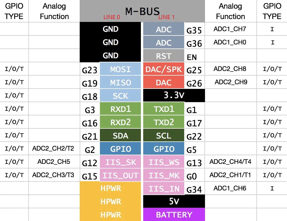
When using the RGB LED on GPIO15, it is recommended to initialize the pin with pinMode(15, OUTPUT_OPEN_DRAIN);
For more information about pin assignment and remapping, please refer to ESP32 datasheet
Datasheets
Softwares
Arduino
UiFlow1
UiFlow2
Easyloader
| Easyloader | Download | Note |
|---|
| M5GO User Demo Easyloader | download | / |
USB Driver
Click the link below to download the driver that matches the operating system. There are currently two driver chip versions (CP210X/CH9102). Please download the corresponding driver compressed package according to the version you are using. After decompressing the compressed package, select the installation package corresponding to the operating system to install. (If you are not sure of the USB chip used by your device, you can install both drivers at the same time. During the installation process of CH9102_VCP_SER_MacOS v1.7, an error may occur, but the installation is actually completed, just ignore it.)
| Driver Name | Applicable Driver Chip | Download Link |
|---|
| CP210x_VCP_Windows | CP2104 | Download |
| CP210x_VCP_MacOS | CP2104 | Download |
| CP210x_VCP_Linux | CP2104 | Download |
| CH9102_VCP_SER_Windows | CH9102 | Download |
| CH9102_VCP_SER_MacOS v1.7 | CH9102 | Download |
\
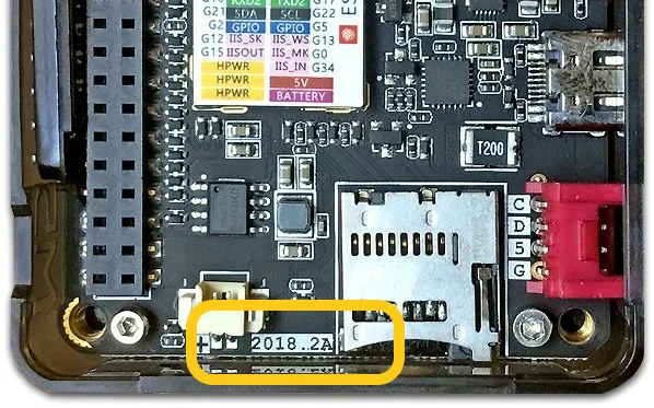
Note: Devices with PCB version
2018.2A do not support C2C (Type-C to Type-C) connection and PD power supply.
Version Change
| Release Date | Product Changes | Note |
|---|
| 2019.11 | Battery capacity changed from 600mAh to 500mAh | / |
| 2019.7 | TN screen changed to IPS screen | Please upgrade your M5Stack library to the latest version (v0.2.8 or above) to solve the screen color inversion problem. |
| 2019.6 | MPU9250 changed to MPU6886+BMM150 | / |
| 2018.4 | First release | / |