

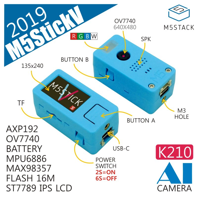
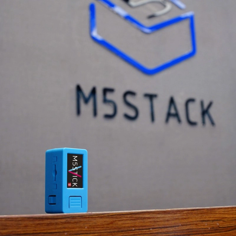
StickV
SKU:K027
Description
StickV is an AIOT (AI + IoT) camera equipped with the Kendryte K210, integrating a dual-core 64-bit RISC-V CPU and a neural network processor edge computing system-on-chip (SoC).
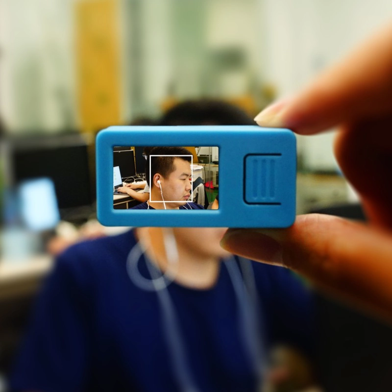
The StickV AI camera has machine vision capabilities, featuring the OmniVision OV7740 image sensor with OmniPixel®3-HS technology, offering superior low-light sensitivity compared to similar products. It supports various visual recognition functions, such as real-time acquisition of the size and coordinates of detected targets, as well as real-time identification of target types. Additionally, the camera can perform convolutional neural network computations with low power consumption, making StickV an excellent zero-threshold embedded machine vision solution.
Moreover, it supports the MicroPython development environment, which makes the program code more concise and refined when developing projects with StickV.
Features
- Dual-core 64-bit RISC-V RV64IMAFDC (RV64GC) CPU / 400MHz (Normal)
- Double-precision FPU
- Neural Network Processor (KPU) / 0.8Tops
- Programmable IO Array (FPIOA)
- Dual hardware 512-point 16-bit complex FFT
- SPI, I2C, UART, I2S, RTC, PWM, timer support
- AES, SHA256 accelerator
- Direct Memory Access Controller (DMAC)
- Supports MicroPython
- Firmware encryption support
- Development Platform
- PlatformIO
Includes
- 1 x StickV
- 1 x USB Type-C (100cm)
- 1 x Stand
- 1 x Hex Wrench
Applications
- Face recognition/detection
- Object detection/classification
- Real-time acquisition of target size and coordinates
- Real-time acquisition of detected target types
- Shape recognition
- Video/display
- Game emulator
Specifications
| Specification | Parameter |
|---|---|
| SoC | Kendryte K210@Dual-Core 64-bit RISC-V RV64GC, Main Frequency 400MHz |
| SRAM | 8MB |
| Flash | 16MB |
| Input Voltage | 5V@500mA |
| KPU Neural Network Parameter Size | 5.5MiB - 5.9MiB |
| Host Interface | USB Type-C x 1, HY2.0-4P (I2C+I/O+UART) x 1 |
| RGB LED | RGBW x 1 |
| Buttons | Custom Buttons x 2 |
| IPS Screen | 1.14 TFT, 135 x 240, ST7789 |
| Camera | OV7740 (0.3MP) |
| FOV | 55° |
| PMU | AXP192 |
| Lithium Battery | 200mAh |
| External Storage | TF-card (microSD) |
| MEMS 6-Axis Sensor | MPU6886 |
| Shell Material | Plastic (PC) |
| Product Size | 48.0 x 24.0 x 22.0mm |
| Product Weight | 23.0g |
| Package Size | 144.0 x 44.0 x 43.0mm |
| Gross Weight | 82.0g |
Learn
Power On/Off Operations
Power On: Press the reset button for at least 2 seconds.
Power Off: Press the reset button for at least 6 seconds.
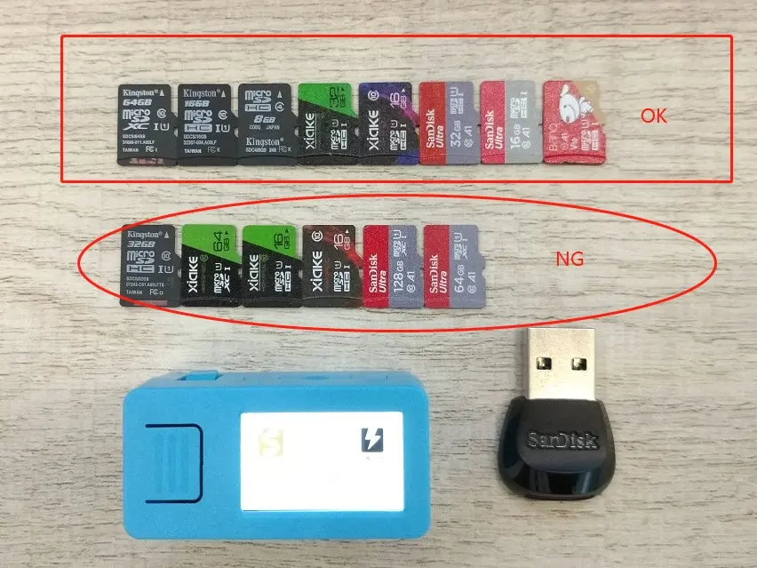
TF-card (microSD) Test
M5StickV currently does not recognize all types of TF-cards (microSD). We have tested some common TF-cards, and the results are as follows.
| Brand | Memory | Type | Transfer Speed | Partition Format | Test Result |
|---|---|---|---|---|---|
| Kingston | 8G | HC | Class4 | FAT32 | OK |
| Kingston | 16G | HC | Class10 | FAT32 | OK |
| Kingston | 32G | HC | Class10 | FAT32 | NO |
| Kingston | 64G | XC | Class10 | exFAT | OK |
| SanDisk | 16G | HC | Class10 | FAT32 | OK |
| SanDisk | 32G | HC | Class10 | FAT32 | OK |
| SanDisk | 64G | XC | Class10 | / | NO |
| SanDisk | 128G | XC | Class10 | / | NO |
| XIAKE | 16G | HC | Class10 | FAT32 | OK (Purple) |
| XIAKE | 32G | HC | Class10 | FAT32 | OK |
| XIAKE | 64G | XC | Class10 | / | NO |
| TURYE | 32G | HC | Class10 | / | NO |
KENDRYTE K210
Kendryte K210 is a system-on-chip (SoC) with integrated machine vision capabilities. Using TSMC's ultra-low-power 28nm advanced process, it features a dual-core 64-bit processor with excellent power efficiency, stability, and reliability. This solution aims for zero-threshold development, enabling rapid deployment into user products, empowering them with artificial intelligence.
- Machine vision capabilities
- Better low-power vision processing speed and accuracy
- Convolutional neural network hardware accelerator KPU for high-performance convolutional neural network computations
- TSMC 28nm advanced process, temperature range -40°C to 125°C, stable and reliable
- Supports firmware encryption, difficult to crack using ordinary methods
- Unique programmable IO array, making product design more flexible
- Low voltage, lower power consumption compared to systems with the same processing power
- 3.3V/1.8V dual voltage support, no level conversion required, cost-saving
CPU
This chip features a dual-core 64-bit high-performance low-power CPU based on the RISC-V ISA, with the following characteristics:
- Core count: Dual-core processor
- Processor width: 64-bit CPU 400MHz
- Nominal frequency: 400MHz
- Instruction set extension: IMAFDC
- Floating-point unit (FPU): Double precision
- Platform interrupt management: PLIC
- Local interrupt management: CLINT
- Instruction cache: 32KiB x 2
- Data cache: 32KiB x 2
- On-chip SRAM: 8MiB
OV7740
- Supported output formats: RAW RGB and YUV
- Supported image sizes: VGA, QVGA, CIF, or smaller sizes
- Supports sunspot elimination
- Supports internal and external frame synchronization
- Standard SCCB serial interface
- Digital video port (DVP) parallel output interface
- Embedded one-time programmable (OTP) memory
- On-chip phase-locked loop (PLL)
- Embedded 1.5 V regulator for the core
- Array size: 656 x 488
- Power supply: - Core: 1.5VDC±5% - Analog: 3.3V±5% - I/O: 1.7~3.47V
- Temperature range: - Operating: -30°C to 70°C - Stable image: 0°C to 50°C
- Output formats: - 8/10-bit raw RGB data - 8-bit YUV
- Lens size: 1/5"
- Input clock frequency: 6~27 MHz
- Maximum image transfer rate: VGA (640x480): 60 fps - QVGA (320 x 240): 120 fps
- Sensitivity: 6800 mV / (Lux-sec)
- Maximum exposure interval: 502 x tROW
- Pixel size: 4.2μm×4.2μm
- Image area: 2755.2μm×2049.6μm
- Package/die size: - CSP3: 4185μm×4345 μm-COB: 4200μm×4360μm
MAX98357
- Single power supply operation (2.5V to 5.5V)
- 3.2W output power: 4Ω, 5V
- 2.4mA quiescent current
- 92% efficiency (RL = 8Ω, POUT = 1W)
- 22.8µVRMS output noise (AV = 15dB)
- 0.015% THD+N at 1kHz
- No MCLK required
- 8kHz to 96kHz sampling rate
- Supports left channel, right channel, and (left channel/2 + right channel/2) output
- Mature edge rate control allows D-class amplifier output without filtering
- 77dB PSRR at 1kHz
- Low RF sensitivity, suppresses GSM emission TDMA noise
- Click-and-pop suppression circuit
AXP192
- Configurable intelligent power selection system
- Adaptive current and voltage limits for USB or AC adapter input
- Internal ideal diode resistance below 100mΩ
MPU6886
Gyroscope Function
- Digital output X, Y, and Z-axis angular rate sensor (gyroscope), user-programmable full-scale range of ±250 dps, ±500 dps, ±1000 dps, and ±2000 dps, integrated 16-bit ADC
- Digital programmable low-pass filter
- Low-power gyroscope operation
- Factory-calibrated sensitivity scale factor
- Lens size: 1/5"
- Self-test
Accelerometer Function
- Digital output X, Y, and Z-axis accelerometer, programmable full-scale range of ±2g, ±4g, ±8g, and ±16g, integrated 16-bit ADC
- User-programmable interrupt
- Wake-on-motion interrupt for low-power operation of application processor
- Self-test
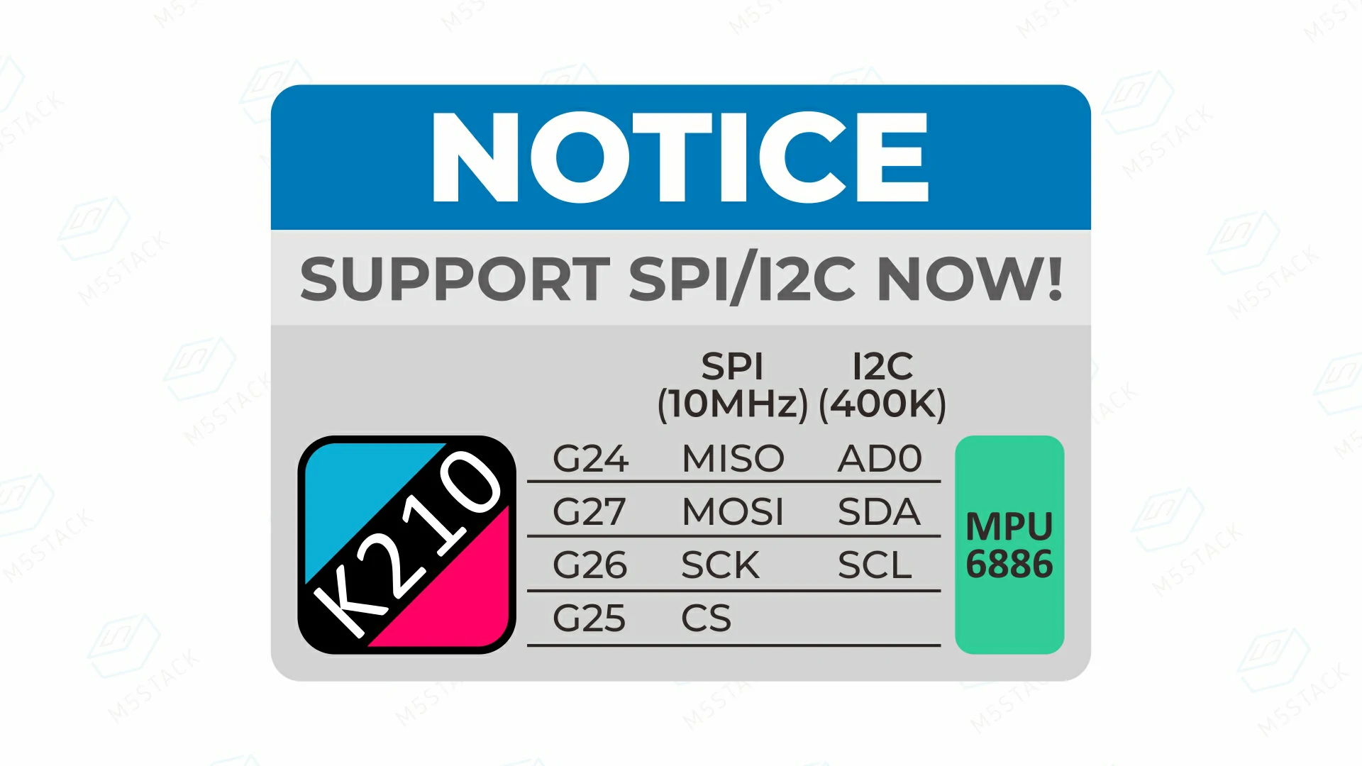
SPI/I2C Dual Communication Mode
Note: Currently, M5Stack has released two versions of M5StickV. Users need to configure the corresponding pin mapping according to the version when programming. The specific differences are as follows.
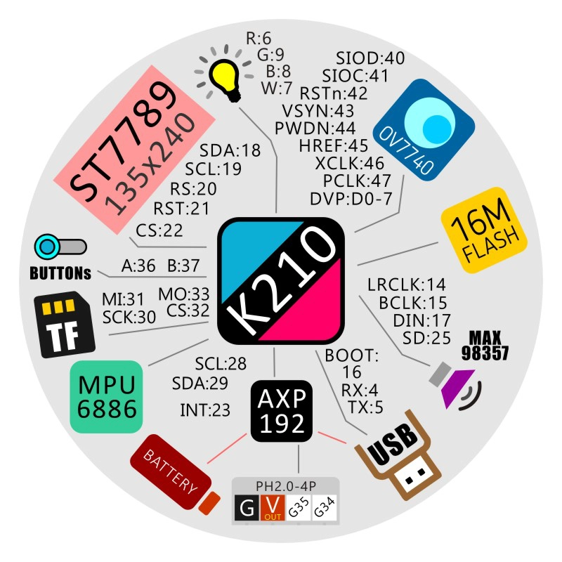
I2C Single Mode (Blue PCB) version of M5StickV: In the circuit design, MPU6886 only supports I2C communication mode, with pin mapping SCL-28, SDA-29.
SPI/I2C Dual Mode (Black PCB) version of M5StickV: In the circuit design, MPU6886 supports both SPI and I2C communication modes, with pin mapping SCL-26, SDA-27. The mode can be switched by toggling the CS pin level (high level 1 for I2C mode, low level 0 for SPI mode).
The specific pin mapping is shown below:
Schematics

Datasheets
Softwares
Quick Start
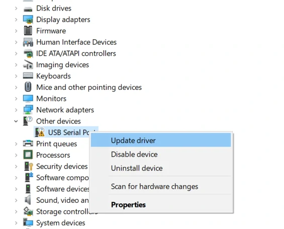
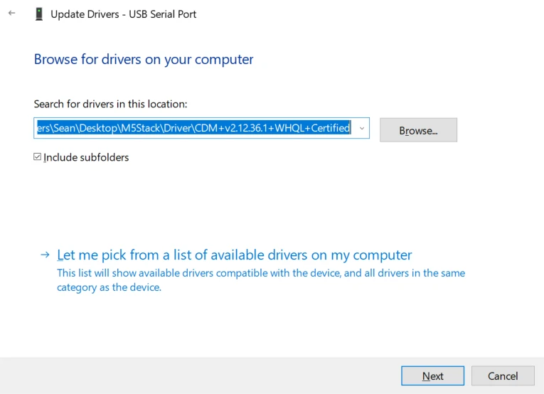
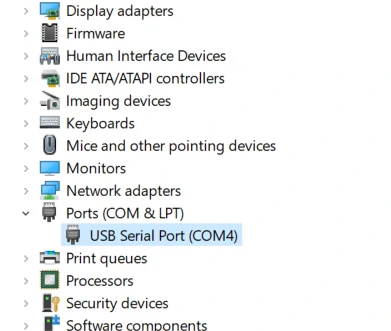
USB Driver
1500000 bps / 750000 bps / 500000 bps / 250000 bps / 115200 bps
Connect the device to a PC, open Device Manager, and install the FTDI driver. For example, in a Windows 10 environment, download the driver file matching the operating system, extract it, and install it via Device Manager. (Note: In some system environments, the driver may need to be installed twice to take effect. The unrecognized device name is usually M5Stack or USB Serial. Windows recommends using the driver file to install directly in Device Manager (custom update). The executable installation method may not work properly). Click here to download the FTDI driver
Easyloader
| Easyloader | Download Link | Notes |
|---|---|---|
| StickV Test Easyloader | download | / |
Video
- Equipped with Maixpy firmware, testing camera and screen graphics display functions. Click the HOME button to turn the backlight on/off.
Product Comparison
To compare information on the UnitV series products, you can visit the Product Selection Table, check the target products, and get the comparison results. The selection table covers key information such as core parameters and functional features, and supports comparison of multiple products simultaneously.
Version Change
| Release Date | Product Changes | Note |
|---|---|---|
| 2020.4 | Added bracket accessory | / |
| 2020.3 | Circuit supports configuring MPU6886 to communicate using SPI or I2C protocol. I2C pins changed: SCL (28=>26), SDA (29=>27) | Drive chip-select pin CS in software to change modes: high level 1 is I2C mode, low level 0 is SPI mode. |
| 2020.3 | Added microphone | / |
| 2019.7 | First release | / |