Station-485
SKU:K123
Description
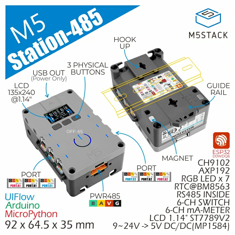
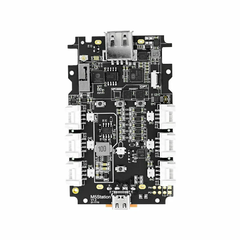
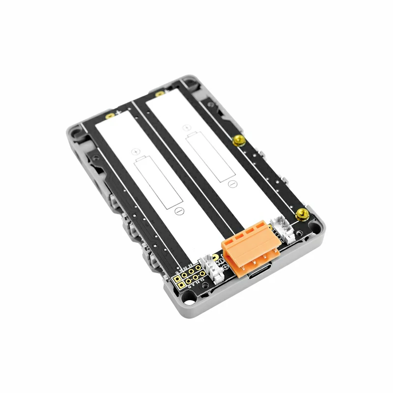
Station-485 is a versatile industrial-grade programmable embedded controller. It uses the Espressif ESP32 as the main control chip, integrates a Wi-Fi solution, and is equipped with a dual-core low-power Xtensa® 32-bit LX6 microprocessor with a clock speed of up to 240MHz. It comes with 16MB Flash and integrates a 240 x 135 1.14-inch full-color HD IPS display panel, physical button panel, rich peripherals, and two sets of six expansion interfaces. It also features low-power sleep/timed wake-up functionality.
It supports multiple power supply methods, including USB Type-C, PWR485, and an internal rechargeable battery (battery socket reserved on the board). The board integrates a high-power-density fully integrated boost DC/DC converter SCT12A0DHKR, ensuring stability in complex application scenarios.
This controller is suitable for various application scenarios such as industrial field control, smart buildings, multi-channel data acquisition nodes, and developer prototyping.
Tutorial
This tutorial will introduce how to control the Station device via the UIFlow graphical programming platform
This tutorial will introduce how to control the Station device via the UiFlow2 graphical programming platform
This tutorial will introduce how to program and control the Station device using the Arduino IDE.
Features
Interactive Design:
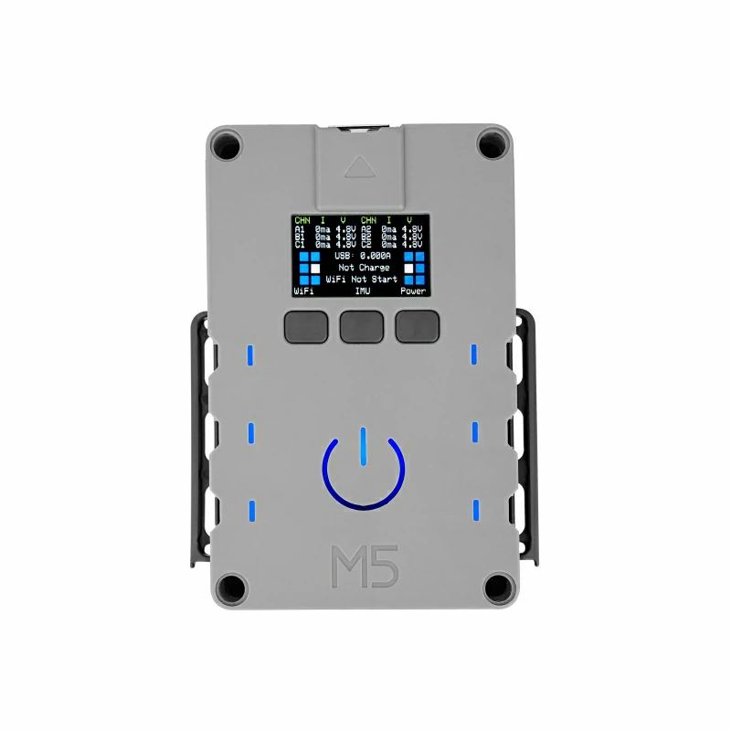
- 1.14-inch IPS display panel
- 3 programmable physical buttons
- 1 power button
- 7 programmable RGB LEDs
Power Design:
- Input:
- Integrated 9~24V to 5V DC/DC SY8303 step-down circuit
- AXP192 power management chip
- Output:
- Each interface (5 Grove, 1 USB-A) uses an electronic switch SGM2553D for independent on/off control
- 6 Grove interfaces use INA3221 for voltage/current monitoring, and USB-A uses INA199 for current monitoring
- Integrated high-power-density fully integrated boost DC/DC converter SCT12A0DHKR
- Low Power Consumption:
- Integrated RTC BM8563 for low-power sleep/timed wake-up
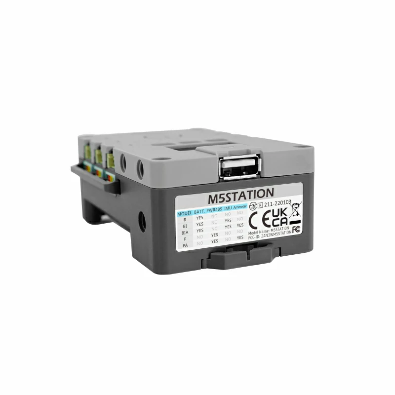
Port Design:
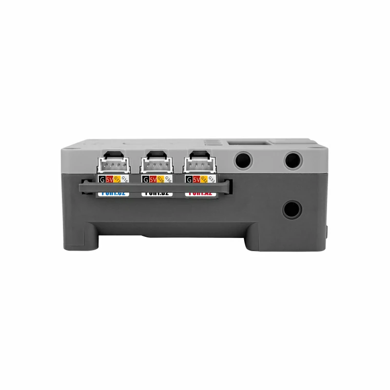
- 6 Grove expansion interfaces
- Port A1/A2 share power and signal pins
- Port B1/B2/C1/C2 have independent power and signal pins
- PWR485 interface (4-wire HT3.96)
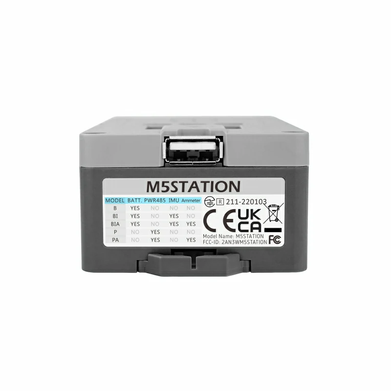
- USB Type-A is for power output only, with no signal pins
Structural Design:
- DIN rail
- Magnetic
- Wall-mounted
- Screws
- Cable ties
Development Platform
- UiFlow1
- UiFlow2
- Arduino IDE
- ESP-IDF
- PlatformIO
Includes
- 1 x Station-485
- 1 x USB Type-C cable (100cm)
- 1 x Hex key
- 1 x I/O Sticker
Applications
- IoT controller
- Multi-channel data acquisition
- IoT product prototyping
- DIY projects
Specifications
| Specification | Parameters |
|---|
| SoC | ESP32-D0WDQ6-V3@dual-core processor, main frequency 240MHz |
| DMIPS | 600 |
| SRAM | 520KB |
| Flash | 16MB |
| Wi-Fi | 2.4 GHz Wi-Fi |
| USB Power | 5V@1A |
| RS485 Power | 9 ~ 24V@1A |
| Host Ports | USB Type-C x 1, HY2.0-4P (I2C+I/O+UART) x 6, Full-Size USB Type-A (OUTPUT), PWR485 |
| LED | SK6812 x 7 |
| Buttons | Power button, physical buttons x 3 |
| IPS LCD Screen | 1.14"@240 x 135 ST7789V2 |
| RTC | BM8563 |
| PMU | AXP192 |
| Voltage/Current Monitor | INA3221 + INA199 |
| USB Chip | CH9102F |
| TTL-RS485 | SP3485 |
| Step-Down Chip | SY8303 |
| DC/DC Boost | SCT12A0DHKR |
| Power Distribution Switch | SGM2553D |
| Antenna | 2.4G 3D antenna |
| Operating Temperature | 0 ~ 60°C |
| Base Screw Specification | M2 x 8 hex socket screws |
| Internal PCB Reserved Interfaces | Battery interface (1.25mm-4P), USB line interface (1.25mm-4P) |
| Housing Material | ABS+PC |
| Product Size | 88.0 x 65.0 x 35.0mm |
| Product Weight | 63.6g |
| Package Size | 104.0 x 73.0 x 54.5mm |
| Gross Weight | 105.3g |
Learn
Power On/Off Operation:
Power On: Click the central power button
Power Off: Long press the central power button for 4 seconds
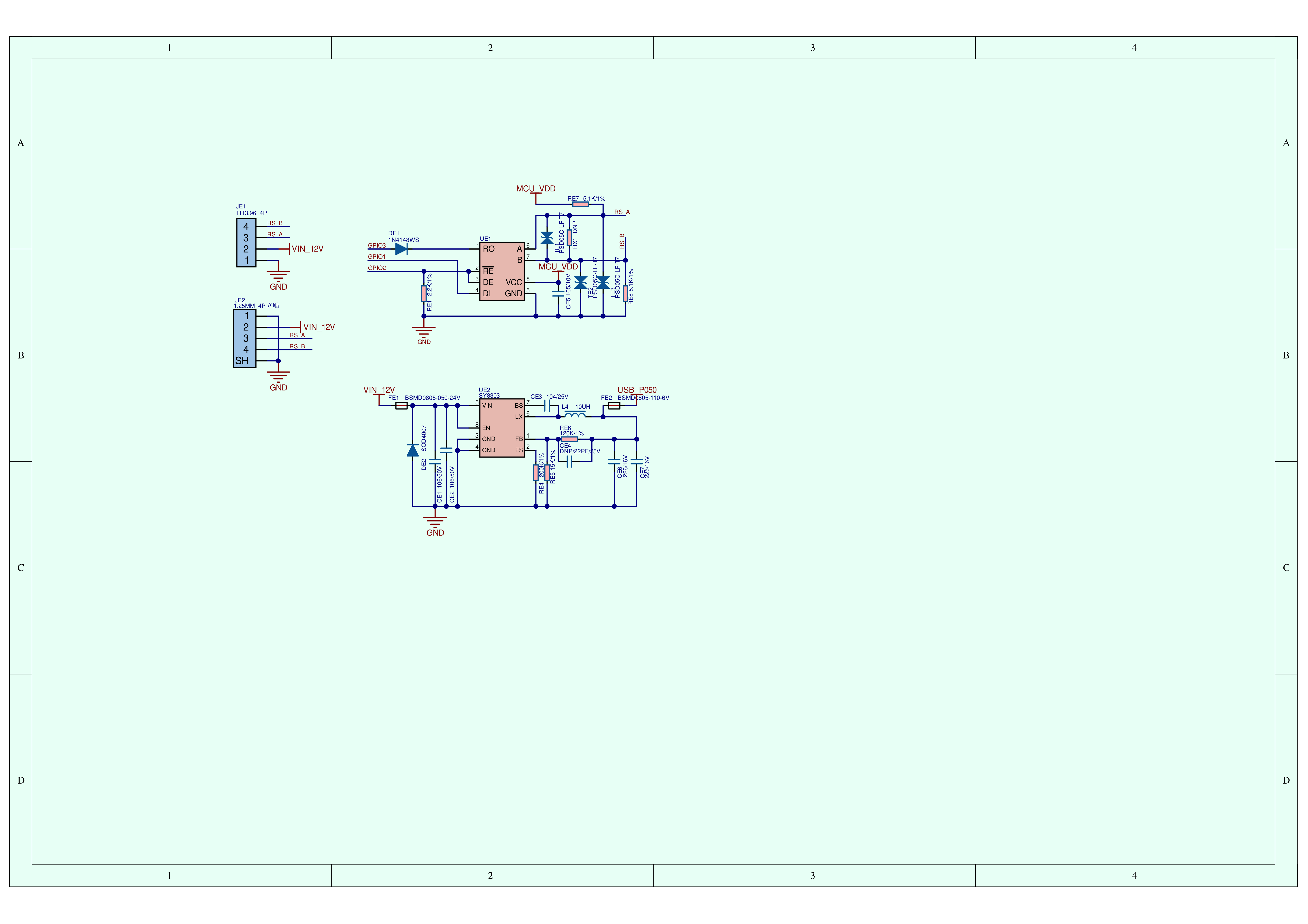
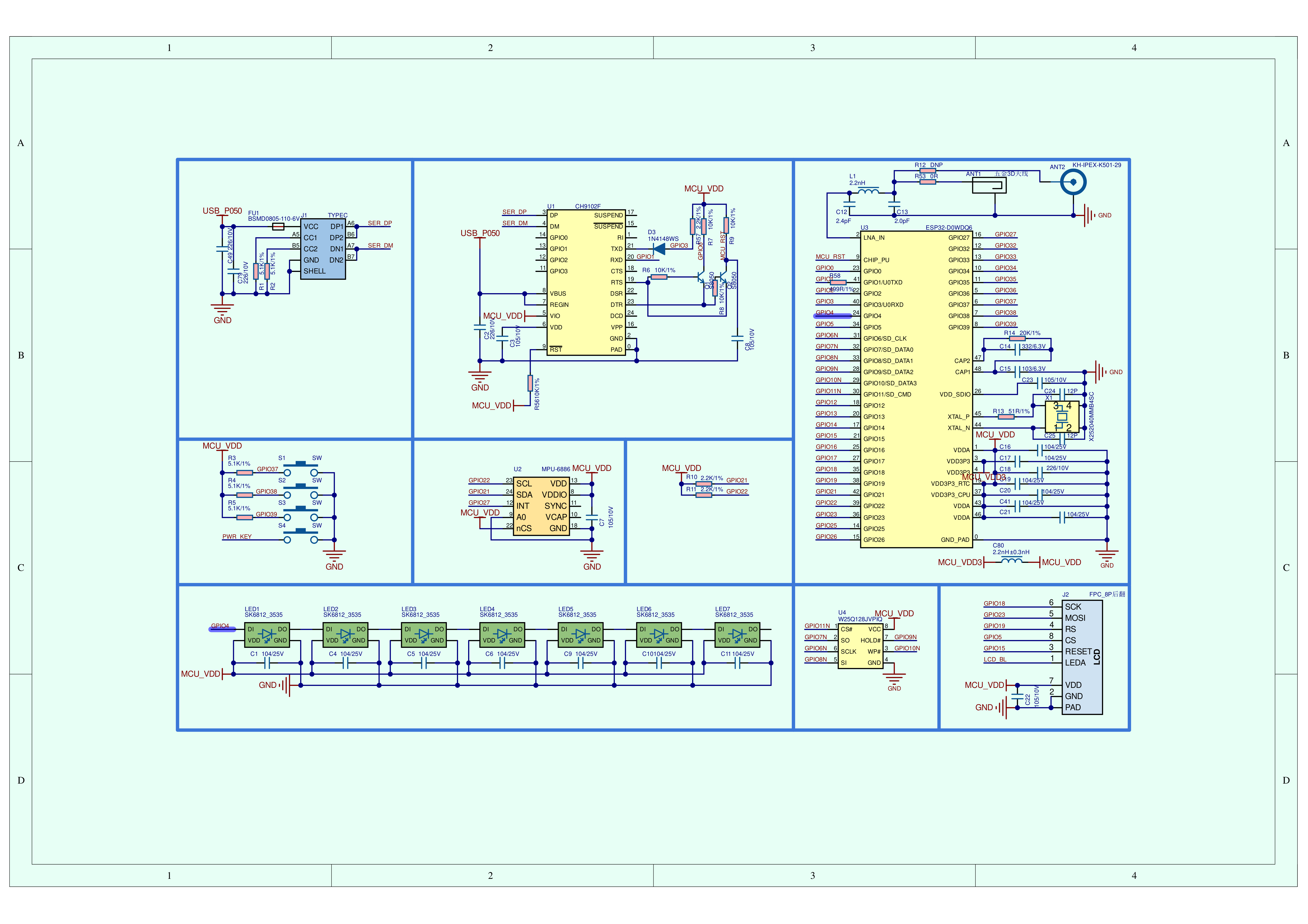
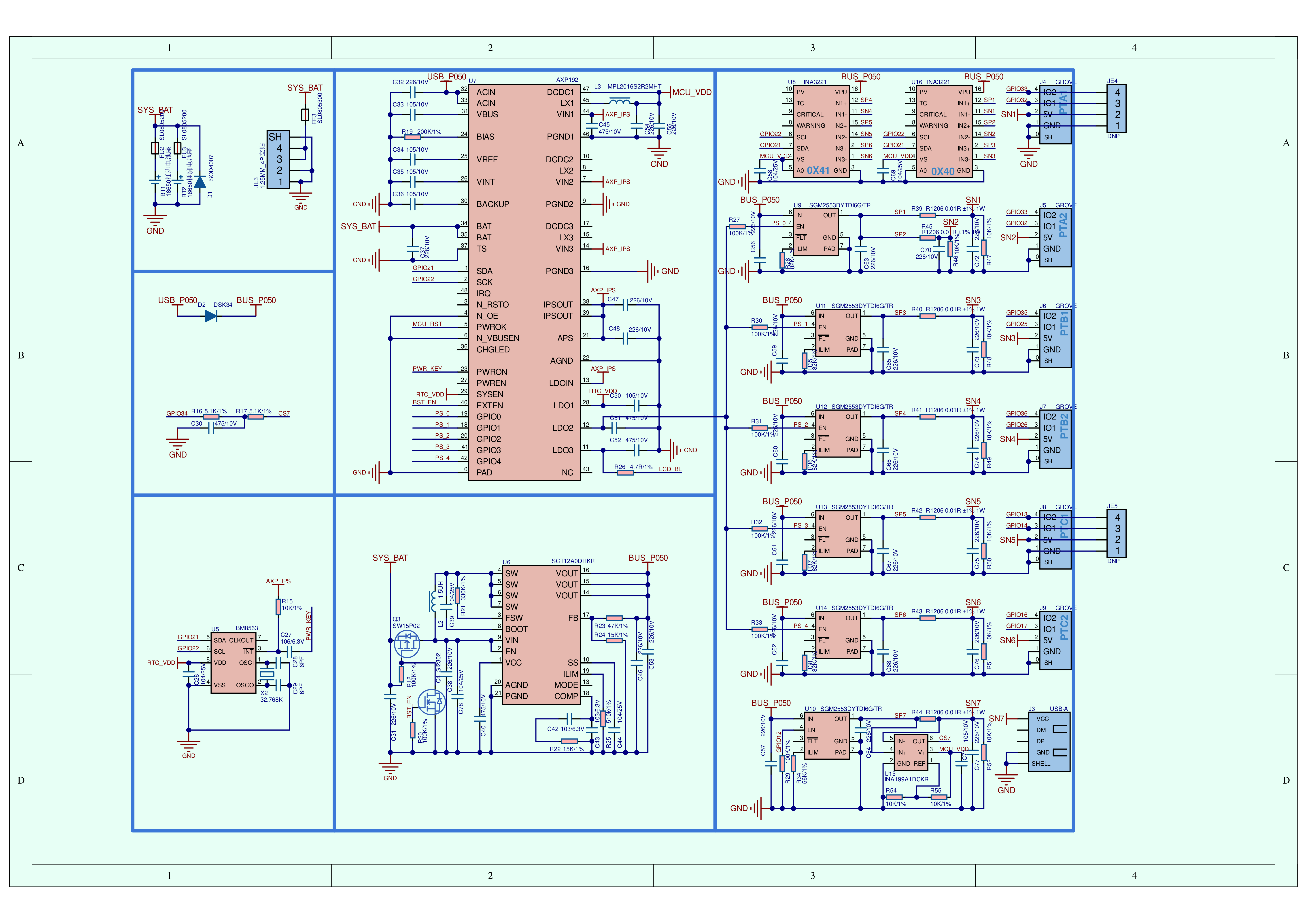
Schematics
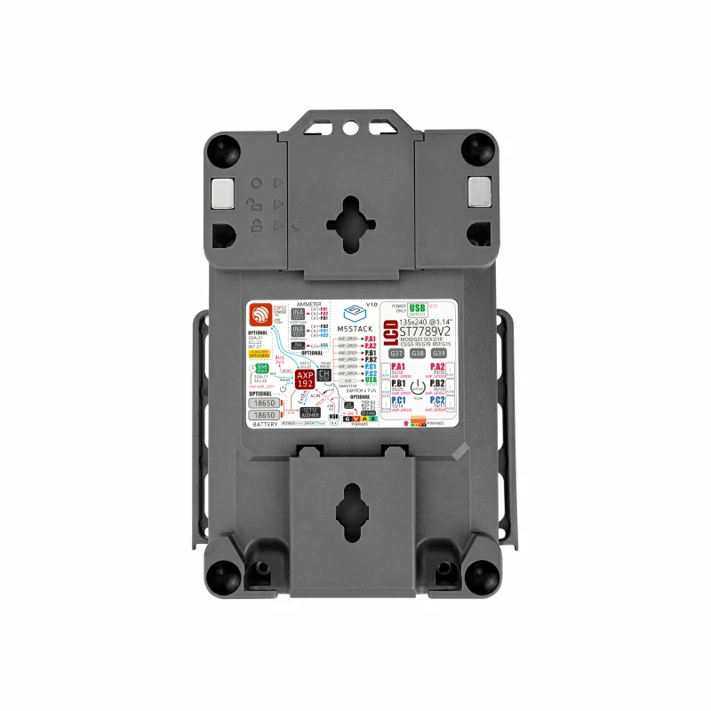
PinMap
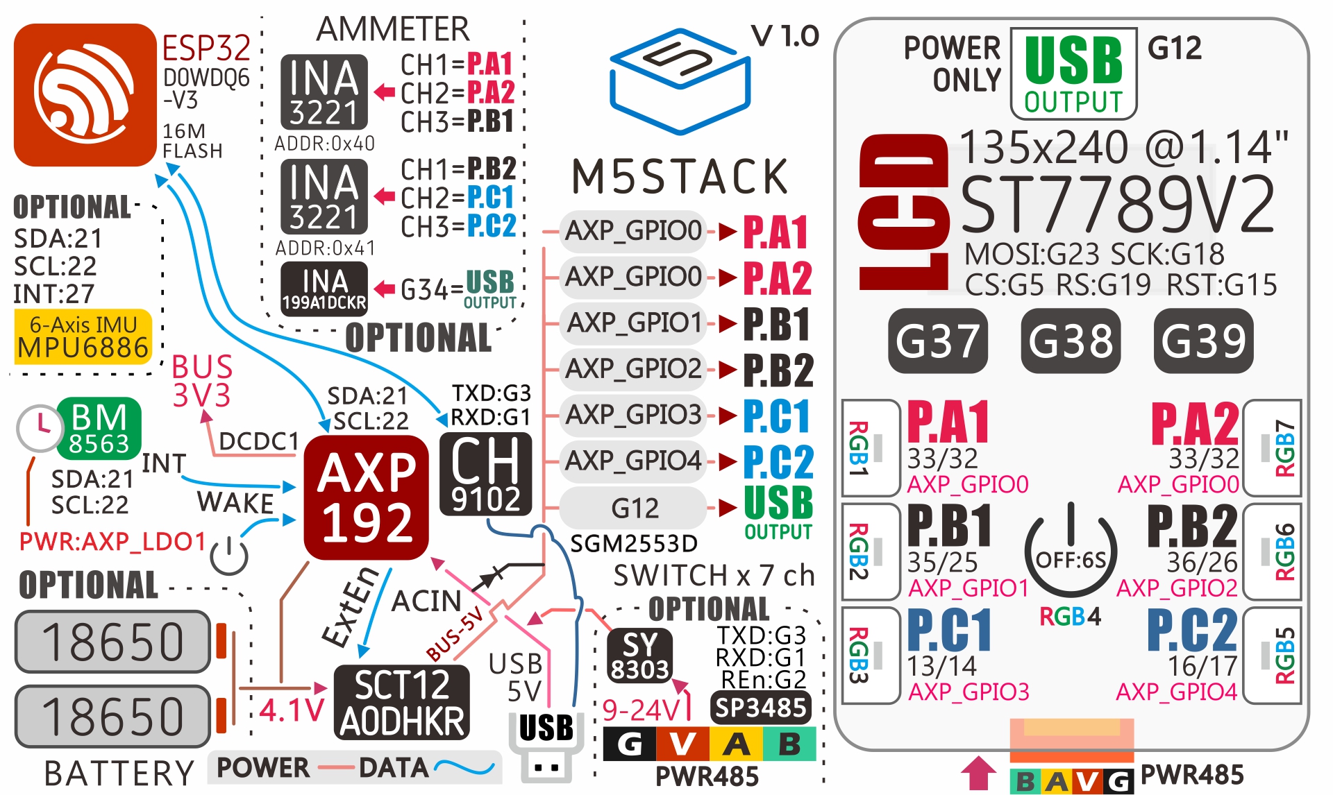
| ESP32-D0WDQ6-V3 | G37 | G38 | G39 |
|---|
| Buttons | BUTTON A | BUTTON B | BUTTON C |
Color TFT Screen
Driver Chip: ST7789v2
Resolution: 135 x 240 @1.14"
| ESP32-D0WDQ6-V3 | G5 | G15 | G18 | G19 | G23 |
|---|
| AXP192 Chip | | | | | |
| LCD | CS(Chip Select) | RESET | SCK(SCLK) | RS(Date/Command) | MOSI |
| AXP192 Chip | AXP_LDO3 |
|---|
| LCD | LCD_BL |
RTC
| ESP32-D0WDQ6-V3 | G21 | G22 |
|---|
| BM8563 | SDA | SCL |
| AXP192 | | |
Current/Voltage Monitor
| ESP32-D0WDQ6-V3 | G21 | G22 | Control Channel |
|---|
| INA3221 (0x40) | SDA | SCL | AXP_GPIO0, AXP_GPIO1 |
| INA3221 (0x41) | SDA | SCL | AXP_GPIO2, AXP_GPIO3, AXP_GPIO4 |
Internal I2C Connection
| ESP32-D0WDQ6-V3 | G21 | G22 |
|---|
| AXP192(0x34) | SDA | SCL |
| BM8563(0x51) | SDA | SCL |
| INA3221(0x40、0x41) | SDA | SCL |
PWR485
| Chip | G3 | G1 | G2 | (DC-DC 9~24V to 5V) | GND |
|---|
| SP3485 | TXD | RXD | Send-High Active/Receive-Low Active | | GND |
| SY8303 | | | | VIN_12V | |
Power Management Chip (AXP192)
| RTC | LCD BackLight | ESP32-3.3V SK6812, INA3221, CH902F |
|---|
| LDO1 | LDO3 | DC-DC1 |
USB to Serial
| ESP32-D0WDQ6-V3 | G3 | G1 |
|---|
| CH9102F | TXD | RXD |
HY2.0-4P
| HY2.0-4P | Black | Red | Yellow | White |
|---|
| PORT.A1 | GND | 5V | G32 | G33 |
| PORT.A2 | GND | 5V | G32 | G33 |
| PORT.B1 | GND | 5V | G25 | G35 |
| PORT.B2 | GND | 5V | G26 | G36 |
| PORT.C1 | GND | 5V | G14 | G13 |
| PORT.C2 | GND | 5V | G17 | G16 |
Power Consumption Test
| Operating Current (LCD, LED, Wi-Fi On) | Standby Current (LCD, LED On) |
|---|
| 161mA | 105mA |
Model Size

Structure
Datasheets
Softwares
Arduino
UiFlow1
UiFlow2
USB Driver
Click the link below to download the driver for your operating system. After extracting the compressed file, select the installation package corresponding to your operating system's bit version. (CH9102_VCP_SER_MacOS v1.7 may report an error during installation, but it is actually installed successfully. Ignore the error.) If you encounter issues such as timeout or "Failed to write to target RAM" when downloading the program, try reinstalling the device driver.
| Driver Name | Applicable Driver Chip | Download Link |
|---|
| CH9102_VCP_SER_Windows | CH9102 | Download |
| CH9102_VCP_SER_MacOS v1.7 | CH9102 | Download |
Easyloader
| Easyloader | Download Link | Remarks |
|---|
| Station-485 Test Easyloader | Download | / |
Product Comparison
| Station-485 | Station-BAT |
|---|
| Equipped with PWR485 (RS485 + Power Input) | Onboard MPU6886, can be equipped with two 18650 batteries (parallel) |
To compare information on the Station series products, you can visit the Product Selection Table, check the target products, and get the comparison results. The selection table covers key information such as core parameters and functional features, and supports comparison of multiple products simultaneously.