

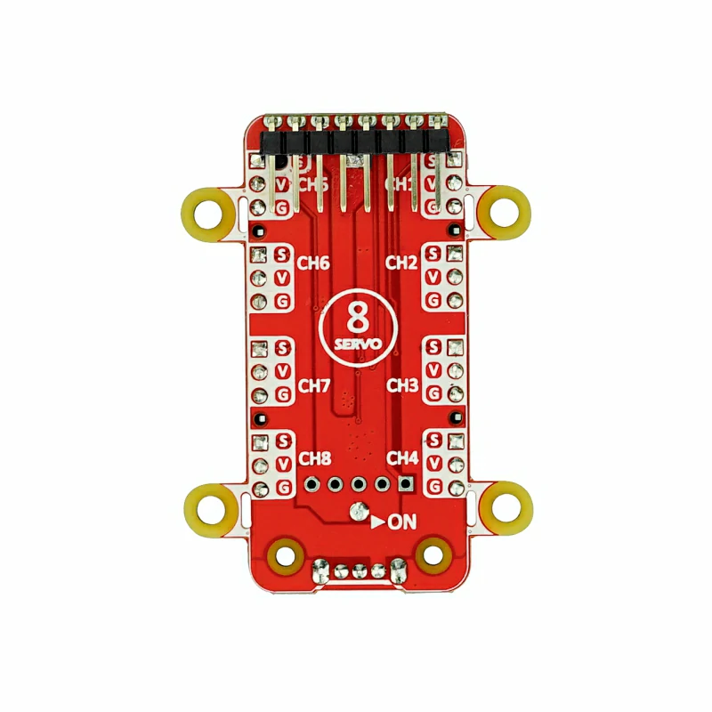
Hat 8Servos v1.1
SKU:U076-B
Description
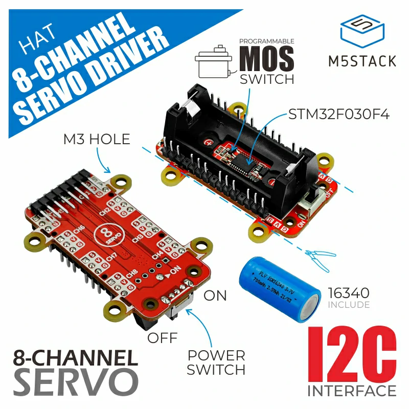
Hat 8Servos v1.1 is an 8-channel servo driver board designed for the M5Stick series. It uses an STM32F030F4 main control to generate multiple PWM signals for servo driving, controlled via the I2C communication protocol to effectively save IO resources. It integrates a MOSFET-based servo power control circuit, supporting programming for dynamic motor power release/lock. Power is provided by rechargeable 16340/18350 lithium batteries (700mAh), also compatible with 18350 lithium batteries. With 8 channels running simultaneously, the maximum load can reach 1.3A, meeting the driving requirements of standard servo specifications.
Features
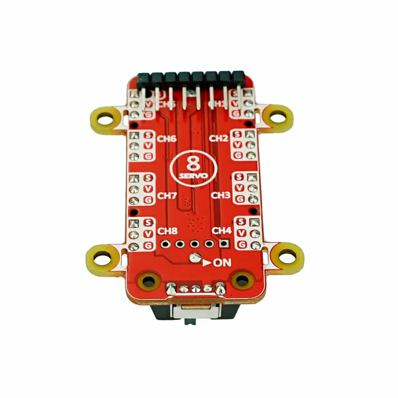
- 8-channel servo drive
- Programmable motor power control
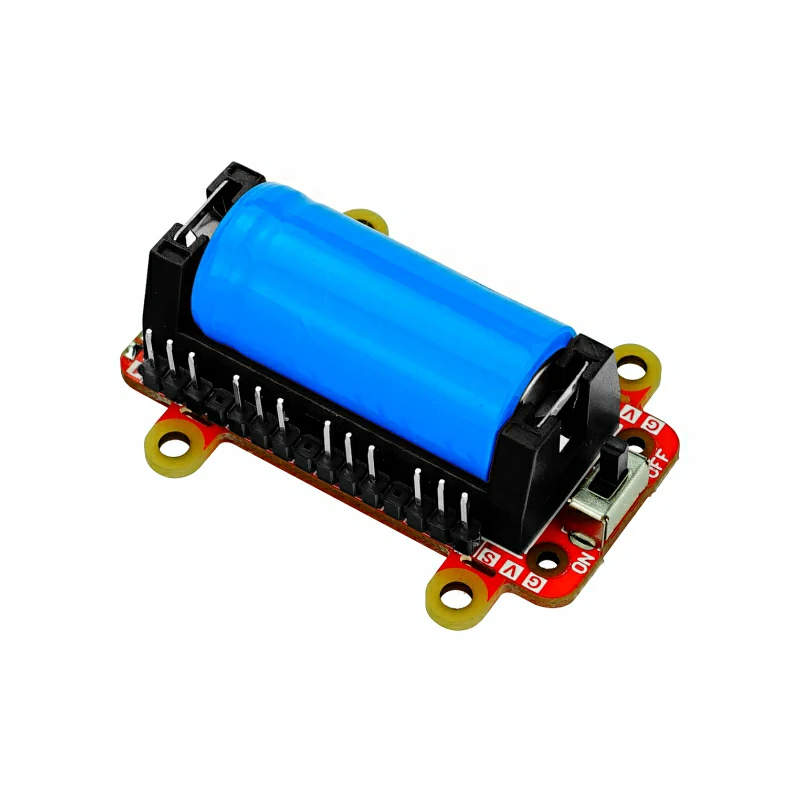
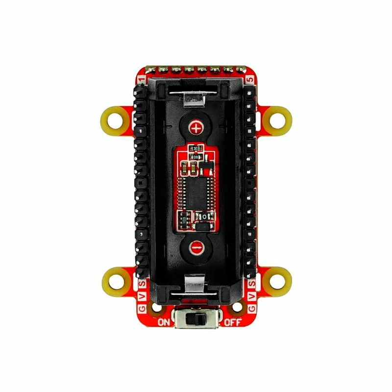
- Powered by 16340/18350 lithium battery
- I2C protocol control (0x36)
- Battery reverse protection
Includes
- 1 x Hat 8Servos v1.1
- 1 x 16340/18350 Battery (700mAh)
Applications
- Servo controller
- Robot control
- Smart toys
Specifications
| Specification | Parameter |
|---|---|
| MCU | STM32F030F4P6 |
| Lithium Battery | Specification: 16340 / 18350, Capacity: 700mAh |
| Servo Driver Channels | 8 Channels |
| Max Load Capacity per Channel | Max Load Capacity for 8 Channels: DC 4.2V@1.3A |
| No-load Standby Current | DC 4.2V@2.2uA |
| Mounting Hole Specification | M3 |
| Communication Interface | I2C Communication @0x36 |
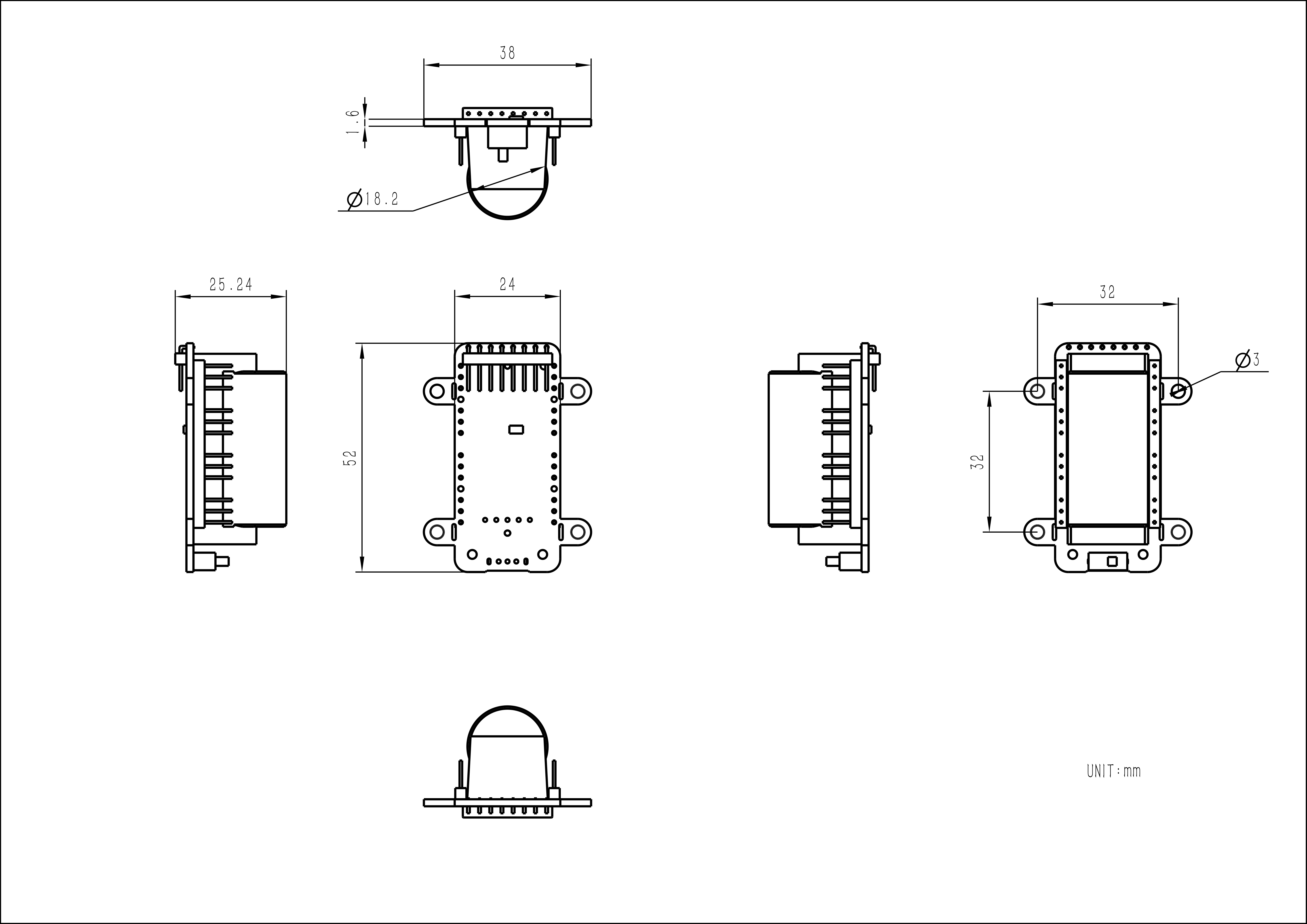
| Product Size | 52.0 x 24.0 x 25.0mm |
| Product Weight | 28.3g |
| Package Size | 75.0 x 46.0 x 29.0mm |
| Gross Weight | 39.7g |
Schematics
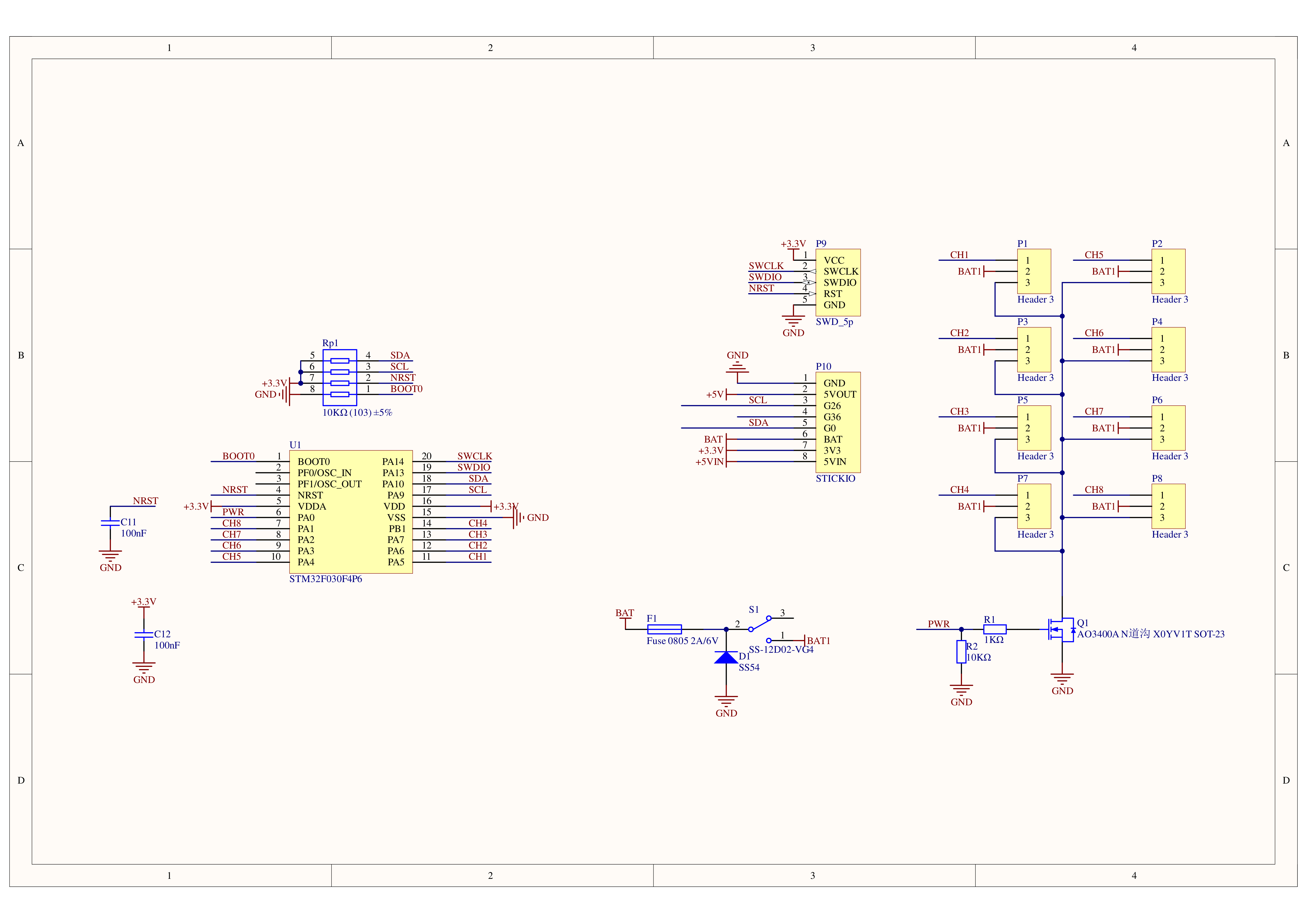
1/1
PinMap
| M5StickC | G0 | G26 | 3.3V | GND |
|---|---|---|---|---|
| 8Servos HAT v1.1 | SDA | SCL | VIN | GND |
Model Size
Softwares
Arduino
- Hat 8Servos v1.1 Arduino Library
- Hat 8Servos v1.1 Example - with M5StickC
- Hat 8Servos v1.1 Example - with M5StickC-Plus
UiFlow1
Internal Firmware
Protocol
- Protocol type: I2C
- I2C Address: 0x36
| hex | len | R/W | description | send params |
|---|---|---|---|---|
| 0x00 | 1 | R/W | CH1 angle output | [0] CH1 angle Valid range: 0-180 |
| 0x01 | 1 | R/W | CH2 angle output | [0] CH2 angle Valid range: 0-180 |
| 0x02 | 1 | R/W | CH3 angle output | [0] CH3 angle Valid range: 0-180 |
| 0x03 | 1 | R/W | CH4 angle output | [0] CH4 angle Valid range: 0-180 |
| 0x04 | 1 | R/W | CH5 angle output | [0] CH5 angle Valid range: 0-180 |
| 0x05 | 1 | R/W | CH6 angle output | [0] CH6 angle Valid range: 0-180 |
| 0x06 | 1 | R/W | CH7 angle output | [0] CH7 angle Valid range: 0-180 |
| 0x07 | 1 | R/W | CH8 angle output | [0] CH8 angle Valid range: 0-180 |
| 0x10 | 2 | R/W | CH1 pulse width output | [0] CH1 pulse width HB [1] CH1 pulse width LB Valid range: 500-2500 |
| 0x12 | 2 | R/W | CH2 pulse width output | [0] CH2 pulse width HB [1] CH1 pulse width LB Valid range: 500-2500 |
| 0x14 | 2 | R/W | CH3 pulse width output | [0] CH3 pulse width HB [1] CH1 pulse width LB Valid range: 500-2500 |
| 0x16 | 2 | R/W | CH4 pulse width output | [0] CH4 pulse width HB [1] CH1 pulse width LB Valid range: 500-2500 |
| 0x18 | 2 | R/W | CH5 pulse width output | [0] CH5 pulse width HB [1] CH1 pulse width LB Valid range: 500-2500 |
| 0x1A | 2 | R/W | CH6 pulse width output | [0] CH6 pulse width HB [1] CH1 pulse width LB Valid range: 500-2500 |
| 0x1C | 2 | R/W | CH7 pulse width output | [0] CH7 pulse width HB [1] CH1 pulse width LB Valid range: 500-2500 |
| 0x1E | 2 | R/W | CH8 pulse width output | [0] CH8 pulse width HB [1] CH1 pulse width LB Valid range: 500-2500 |
| 0x30 | 1 | R/W | MOS servo power control | [0] MOS_CTL Valid range: 0 (power off)/1 (power on) |
Product Comparison
| Specification | 8Servos HAT | 8Servos HAT v1.1 |
|---|---|---|
| Motor Power Control | / | MOSFET control power on/off |
| Battery Reverse Protection | / | Protection circuit |
| Mounting Ears | / | 4x removable ears with mounting holes |
| Programmable RGB LED | SK6812 | / |
| I2C ADDR | 0x38 | 0x36 |