Gray
SKU:K002
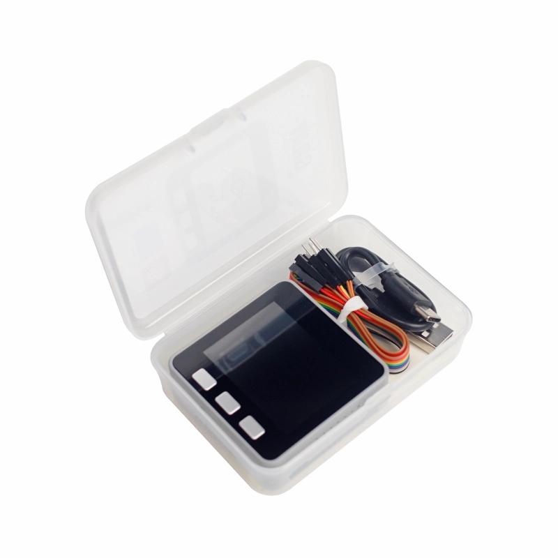
Description
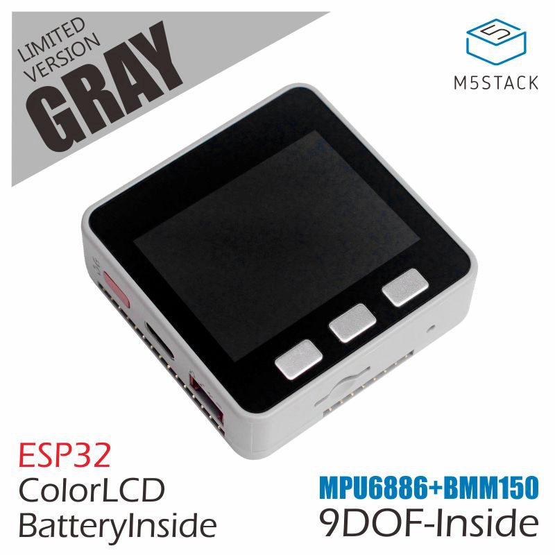
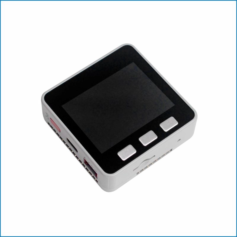
Gray is an advanced development kit in the M5Stack series. As an upgraded version of the Basic kit, it offers larger Flash memory and integrates the IMU sensor MPU6886+BMM150. Whether for beginners or advanced users, the Gray kit is an excellent choice.
The IMU attitude sensor can be used in many applications to detect data such as acceleration, angle, and trajectory extension. Based on this, you can create related products such as motion data collectors and 3D remote gesture controllers.
With rapid prototyping and a very low threshold, the M5Stack development board is your best choice for IoT development. Traditional development boards can only be used for verification and learning, but the M5Stack board offers more possibilities. It features an industrial-grade case and exquisite design, providing stable performance. Besides verification and learning, it can also accelerate development and productization. It uses the ESP32 IoT chip, integrates a Wi-Fi module, has 4MB of SPI flash, and its dual-core low-power design performs exceptionally in various applications. The hardware expansion system, consisting of over 30 stackable M5Stack modules and over 40 expandable units, can quickly help you build and verify your IoT products.
Tutorial
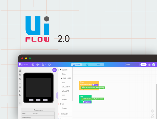
Supported development platforms and programming languages: Arduino, UIFlow Blockly language, Micropython. No matter your development and programming skill level, M5Stack will assist you in gradually turning your ideas into reality.
If you have developed with ESP8266, you will find that ESP32 is a perfect upgrade. Compared to ESP8266, ESP32 has more GPIOs, more analog inputs, two analog outputs, and multiple peripheral interfaces (such as spare UART). The official development platform ESP-IDF has ported FreeRTOS, which, with dual-core and real-time operating system, allows you to organize your program code more efficiently and optimize program execution efficiency.


Features
- Based on ESP32 development
- Large capacity flash
- Integrated 3-axis gyroscope, 3-axis accelerometer, and 3-axis magnetometer
- Built-in speaker, buttons, LCD screen, power/reset button
- TF card slot (supports up to 16GB)
- Built-in lithium battery
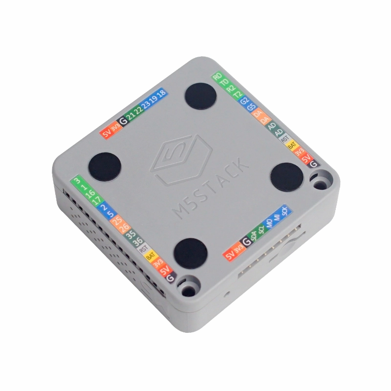
- Back magnetic design
- Expandable pins and interfaces
- M5-Bus socket & pins
- Development Platform
- UiFlow1
- UiFlow2
- Arduino IDE
- ESP-IDF
- PlatformIO
Includes
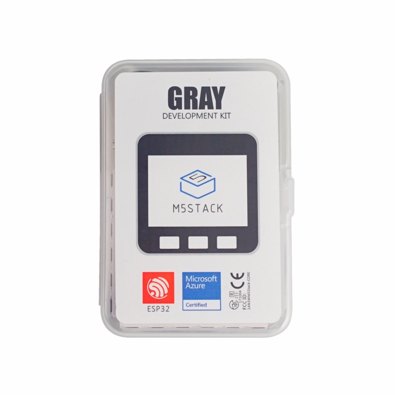
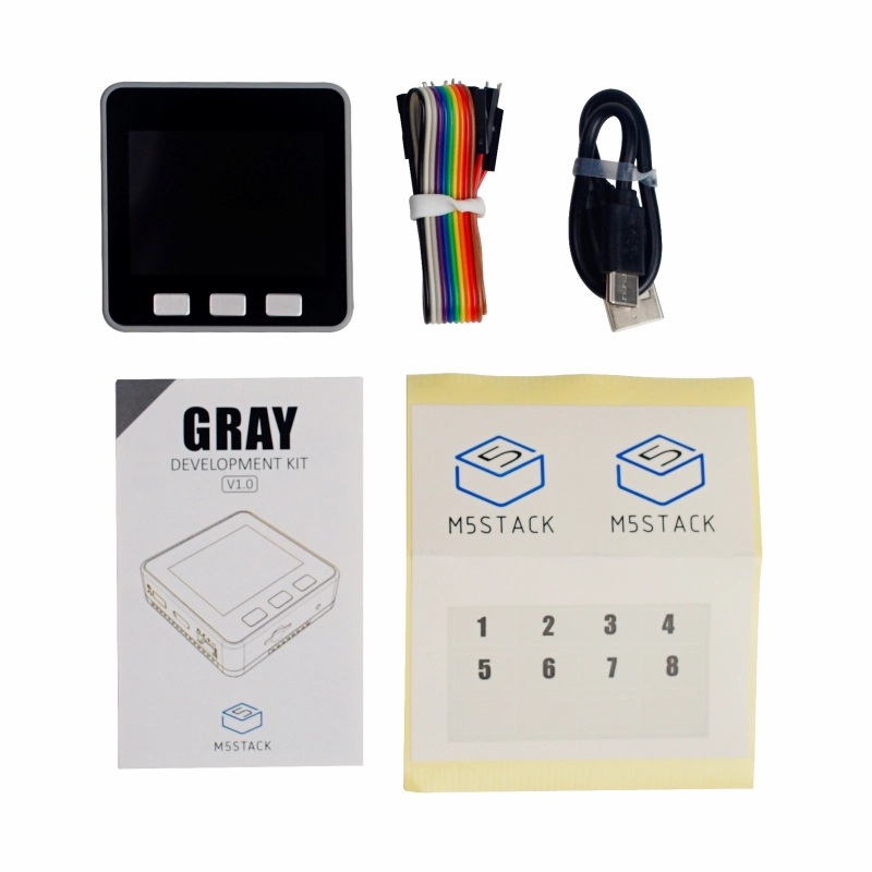
- 1 x Gray
- 10 x Dupont wires
- 1 x USB Type-C cable (20cm)
- 1 x User manual
- 1 x Sticker
Applications
- IoT controllers
- STEM education
- DIY projects
- Smart home devices
Specifications
| Main Control Resources | Parameter |
|---|---|
| SoC | ESP32-D0WDQ6 @ Xtensa® 32-bit LX6 dual-core processor, clock frequency 240MHz |
| DMIPS | 600 |
| SRAM | 520KB |
| Flash | 16MB |
| Wi-Fi | 2.4 GHz Wi-Fi |
| Input Voltage | 5V@500mA |
| Interface | USB Type-C x 1, GROVE (I2C+I/O+UART) x 1 |
| IPS Screen | 2 inch, 320x240 Colorful TFT LCD, ILI9342C, Max brightness 853nit |
| Speaker | 1W-0928 |
| Core Base Interface | PIN (G1, G2, G3, G16, G17, G18, G19, G21, G22, G23, G25, G26, G35, G36) |
| MEMS | MPU6886+BMM150 |
| Buttons | Custom buttons x 3 |
| Battery | 110mAh@3.7V |
| Antenna | 2.4G 3D antenna |
| Operating Temperature | 0 ~ 60°C |
| Case Material | Plastic (PC) |
| Product Size | 54.0 x 54.0 x 17.0mm |
| Product Weight | 47.7g |
| Package Size | 94.8 x 65.4 x 25.3mm |
| Gross Weight | 92.0g |
Learn
Power On/Off
Power Off: Quickly double-click the red power button on the left
Note: By default, the device cannot be turned off when powered by USB
Schematics
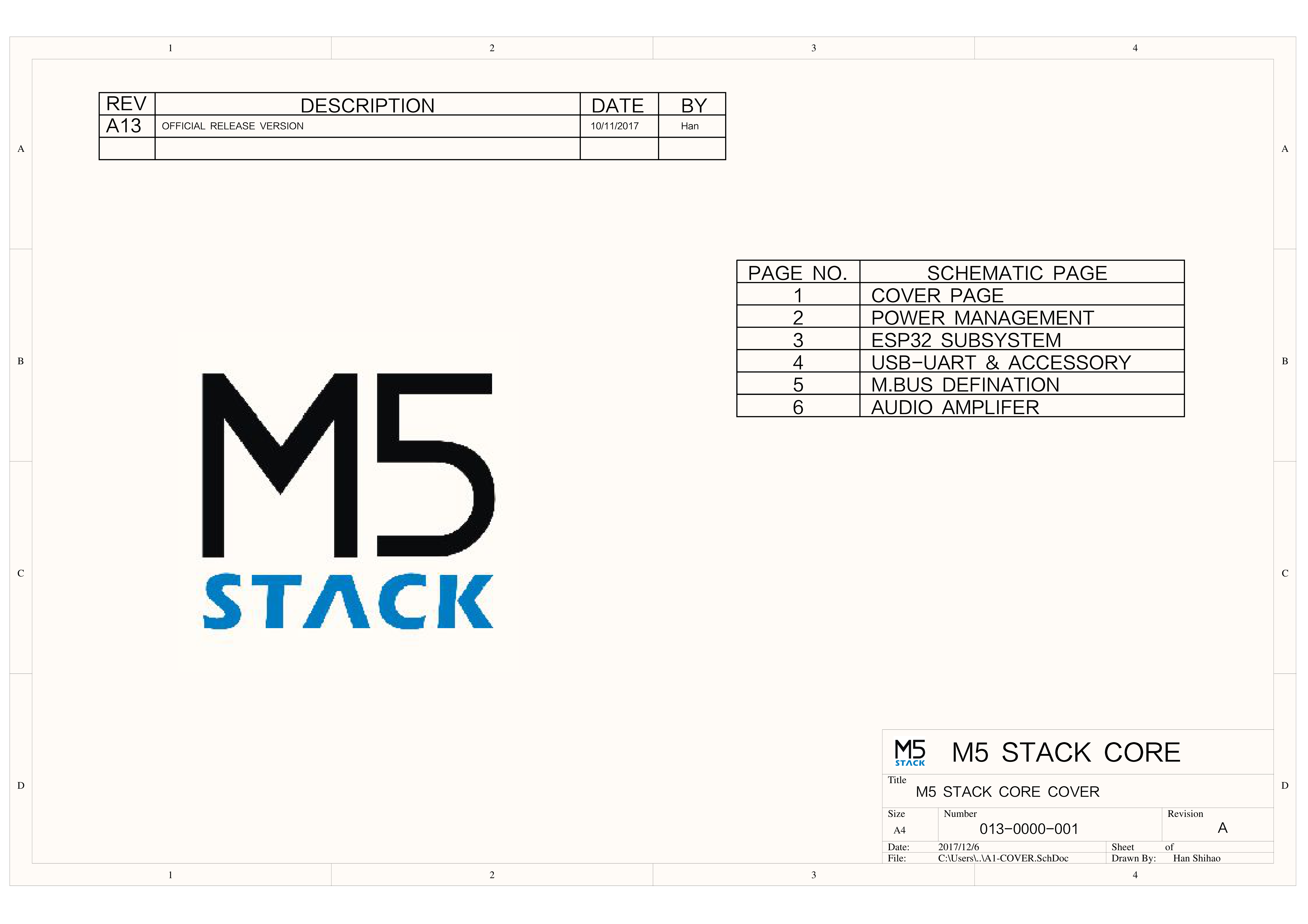
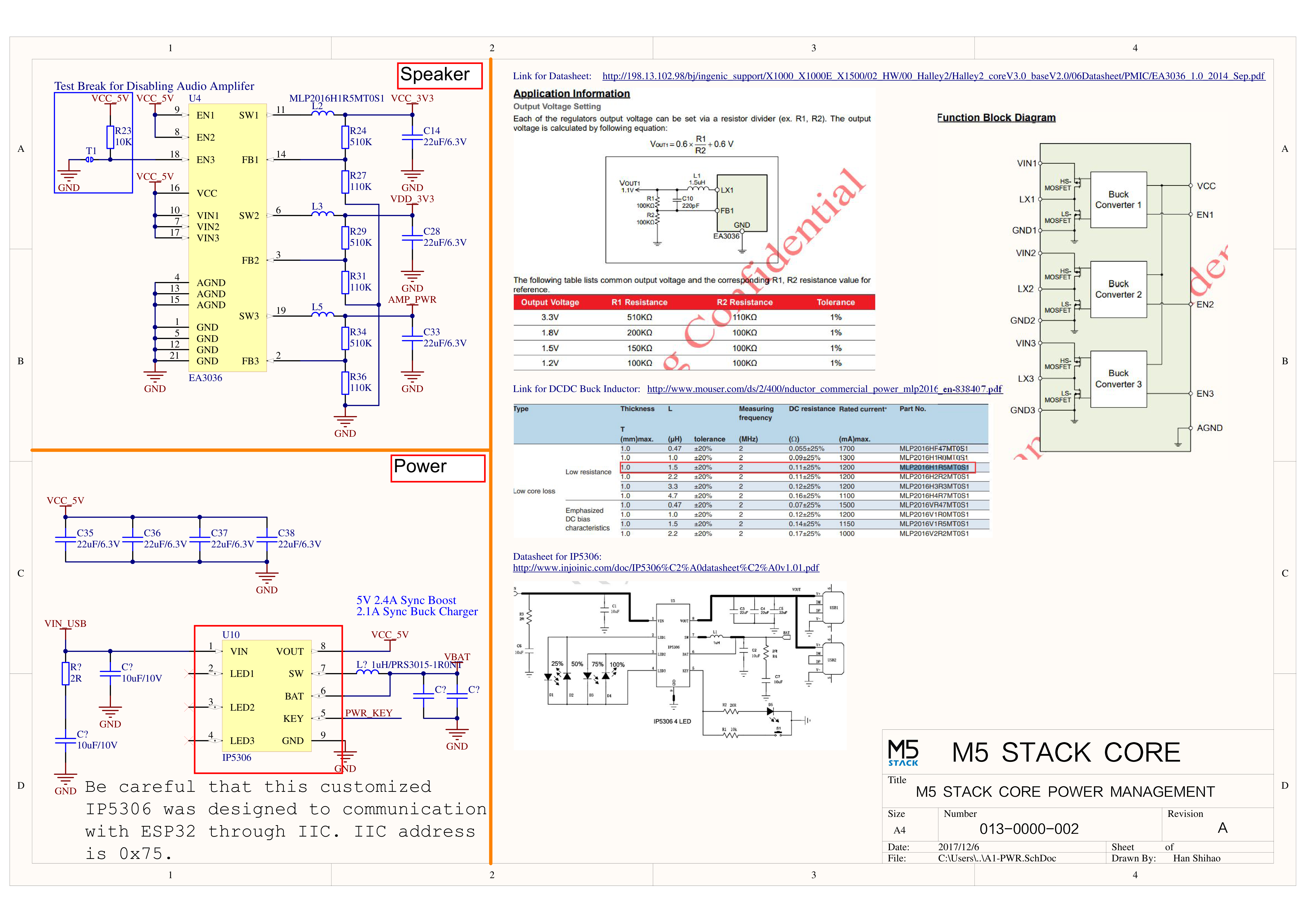
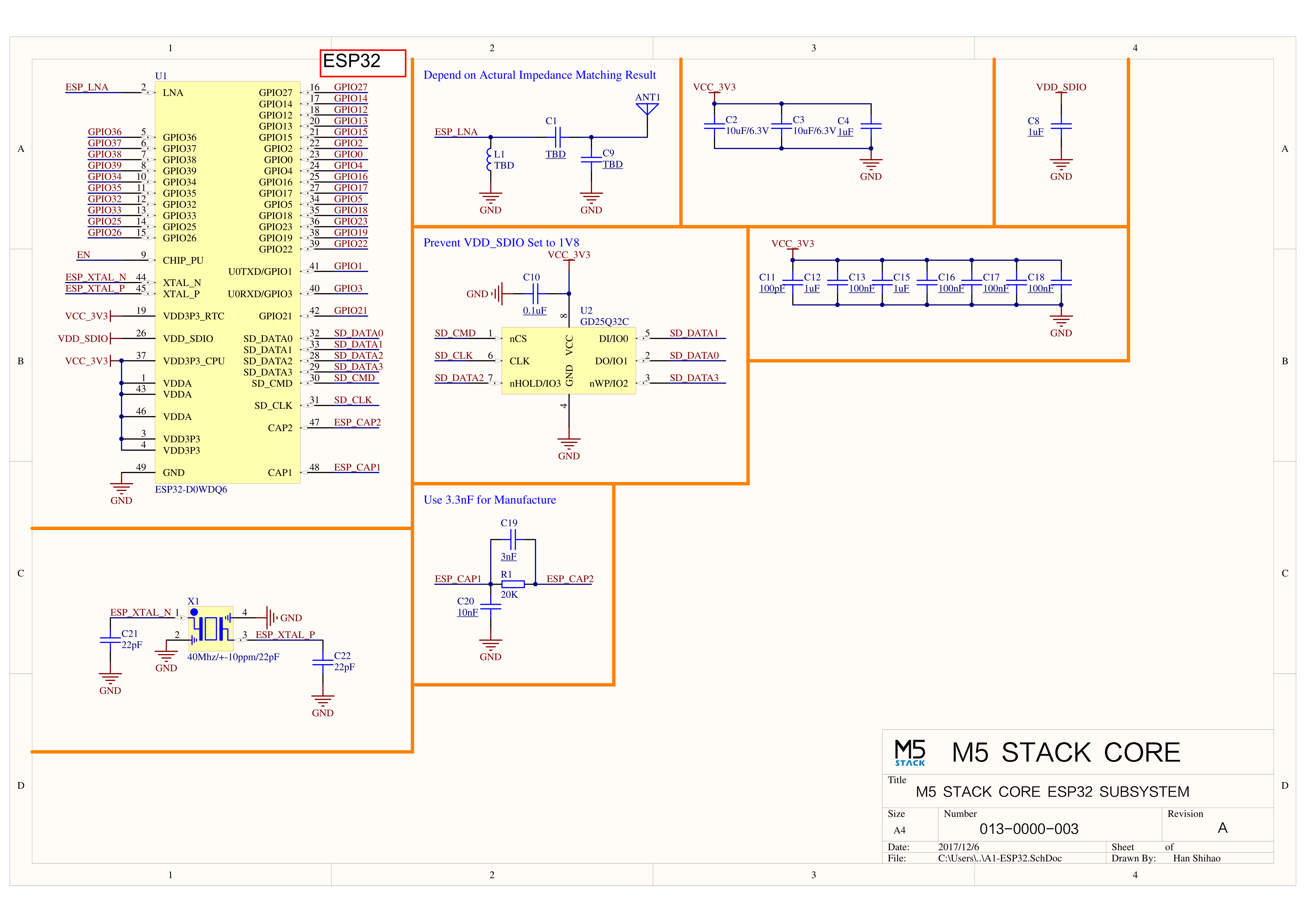
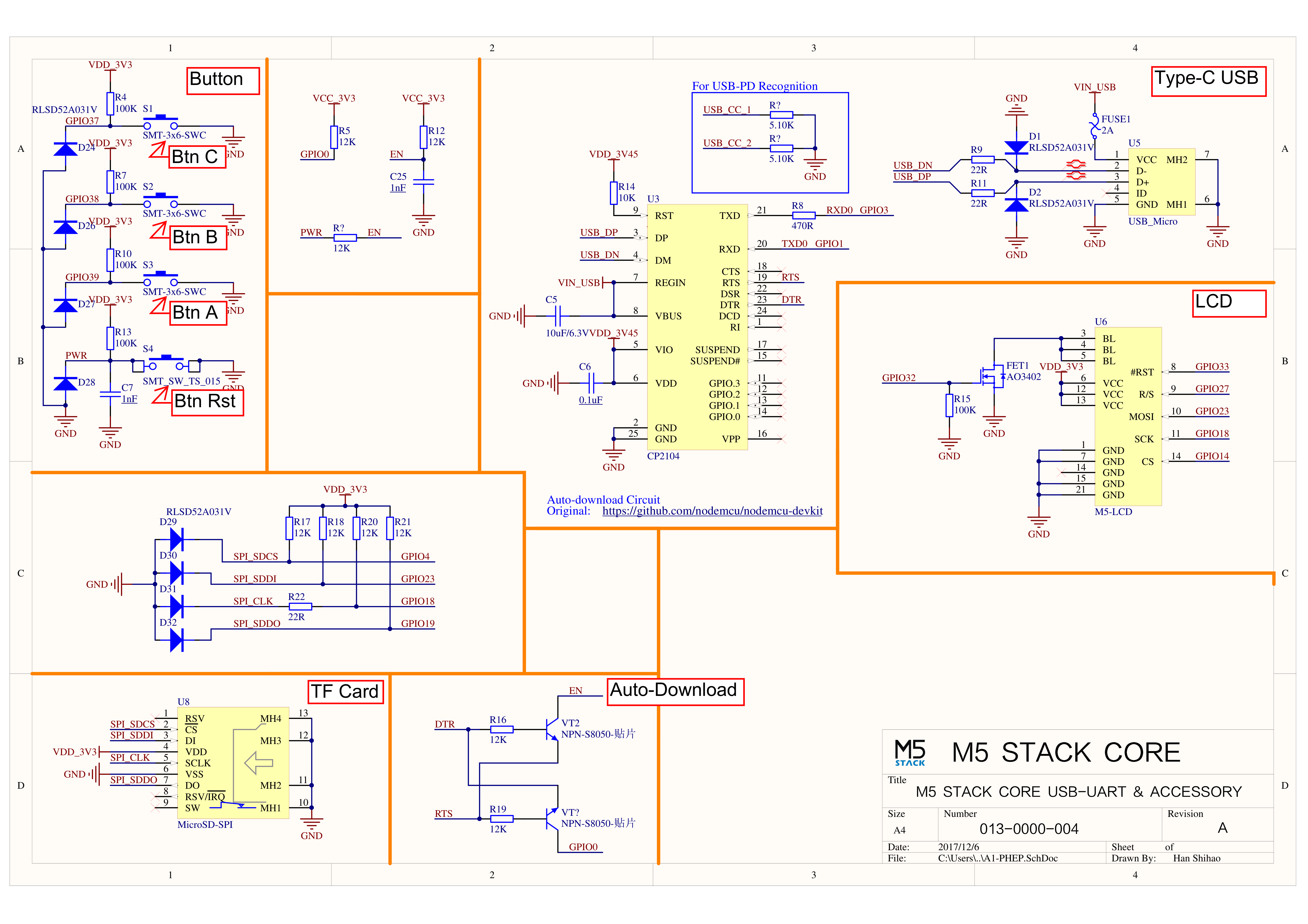
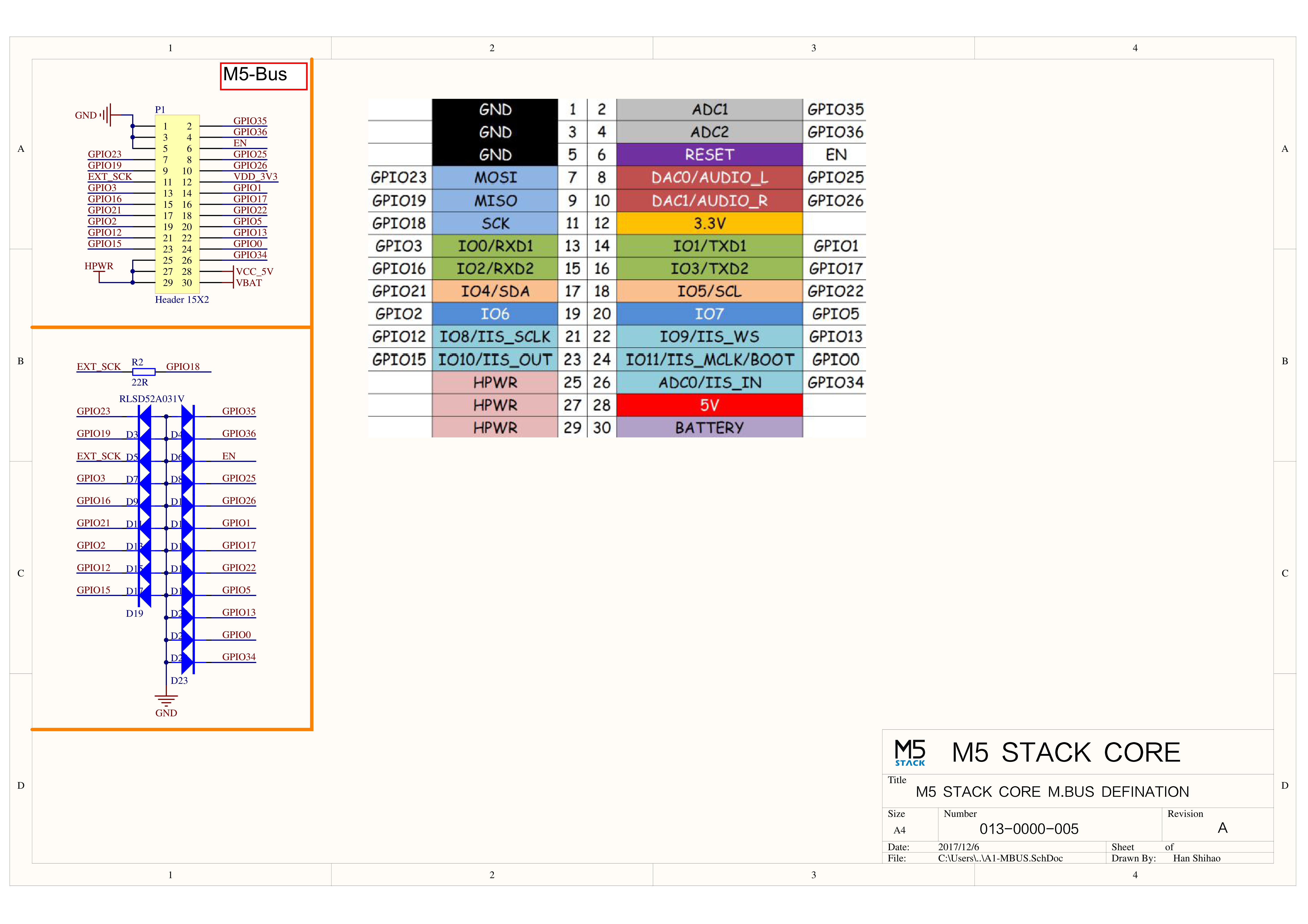
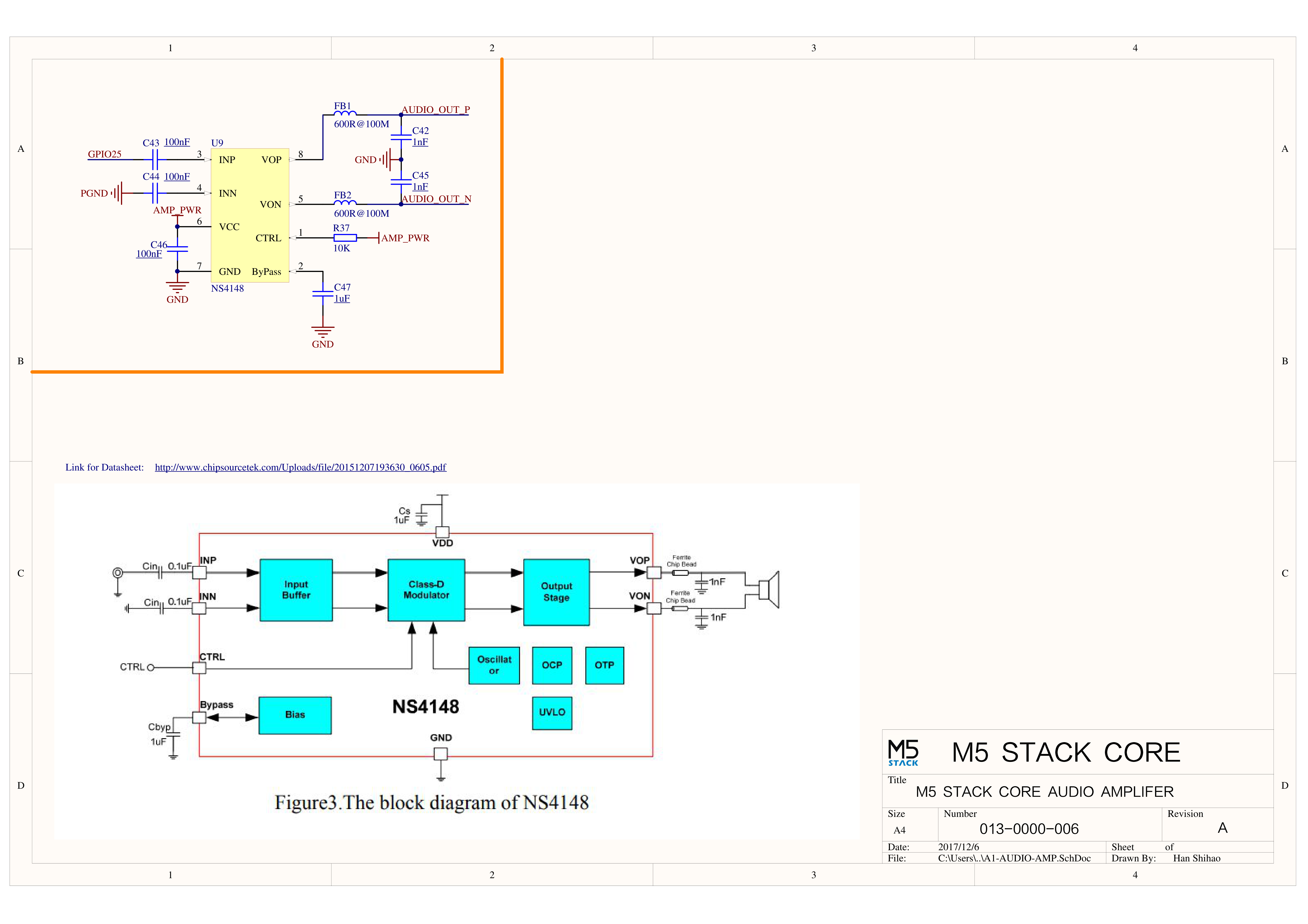
PinMap
LCD Screen & TF Card
LCD Pixels: 320 x 240
TF Card supports up to 16GB
| ESP32-D0WDQ6 | G23 | G19 | G18 | G14 | G27 | G33 | G32 | G4 |
|---|---|---|---|---|---|---|---|---|
| ILI9342C | MOSI/MISO | / | CLK | CS | DC | RST | BL | |
| TF Card | MOSI | MISO | CLK | CS |
Buttons & Speaker
| ESP32-D0WDQ6 | G39 | G38 | G37 | G25 |
|---|---|---|---|---|
| Button Pins | BUTTON A | BUTTON B | BUTTON C | |
| Speaker | Speaker Pin |
GROVE Interface A & IP5306
The power management chip (IP5306) is a custom I2C version with an I2C address of 0x75. Click here to view the IP5306 register manual.
| ESP32-D0WDQ6 | G22 | G21 | 5V | GND |
|---|---|---|---|---|
| GROVE A | SCL | SDA | 5V | GND |
| IP5306 (0x75) | SCL | SDA | 5V | GND |
IP5306 Charge/Discharge Voltage Parameters
| Charging | Discharging |
|---|---|
| 0.00 ~ 3.40V -> 0% | 4.20 ~ 4.07V -> 100% |
| 3.40 ~ 3.61V -> 25% | 4.07 ~ 3.81V -> 75% |
| 3.61 ~ 3.88V -> 50% | 3.81 ~ 3.55V -> 50% |
| 3.88 ~ 4.12V -> 75% | 3.55 ~ 3.33V -> 25% |
| 4.12 ~ / -> 100% | 3.33 ~ 0.00V -> 0% |
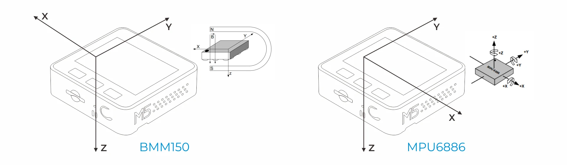
MPU6886
MPU6886 I2C address 0x68
| ESP32-D0WDQ6 | G22 | G21 | 5V | GND |
|---|---|---|---|---|
| MPU6886 (0x68) | SCL | SDA | 5V | GND |
BMM150
BMM150 I2C address is 0x10
| ESP32-D0WDQ6 | G22 | G21 | 5V | GND |
|---|---|---|---|---|
| BMM150 (0x10) | SCL | SDA | 5V | GND |
Charging Current Measurements
| Charging Current | Current After Full Charge (Off) | Full Charge (On) |
|---|---|---|
| 1.069A | - | 0.073A |
ESP32 ADC/DAC
| ADC1 | ADC2 | DAC1 | DAC2 |
|---|---|---|---|
| 8 Channels | 10 Channels | 2 Channels | 2 Channels |
| G32-39 | G0/2/4/12-15/25-27 | G25 | G26 |
HY2.0-4P
| HY2.0-4P | Black | Red | Yellow | White |
|---|---|---|---|---|
| PORT.A | GND | 5V | G21 | G22 |
| PORT.B | GND | 5V | G26 | G36 |
| PORT.C | GND | 5V | G17 | G16 |
M5-Bus
| FUNC | PIN | LEFT | RIGHT | PIN | FUNC |
|---|---|---|---|---|---|
| GND | 1 | 2 | G35 | ADC | |
| GND | 3 | 4 | G36 | ADC | |
| GND | 5 | 6 | RST | EN | |
| MOSI | G23 | 7 | 8 | G25 | DAC/SPK |
| MISO | G19 | 9 | 10 | G26 | DAC |
| SCK | G18 | 11 | 12 | 3V3 | |
| RXD0 | G3 | 13 | 14 | G1 | TXD0 |
| RXD2 | G16 | 15 | 16 | G17 | TXD2 |
| Int SDA | G21 | 17 | 18 | G22 | Int SCL |
| GPIO | G2 | 19 | 20 | G5 | GPIO |
| I2S_SK | G12 | 21 | 22 | G13 | I2S_WS |
| I2S_OUT | G15 | 23 | 24 | G0 | I2S_MK |
| HPWR | 25 | 26 | G34 | I2S_IN | |
| HPWR | 27 | 28 | 5V | ||
| HPWR | 29 | 30 | BAT |
For more information on pin allocation and pin remapping, refer to the ESP32 datasheet
Datasheets
Softwares
Arduino
UiFlow1
UiFlow2
USB Driver
| Driver Name | Applicable Driver Chip | Download Link |
|---|---|---|
| CP210x_VCP_Windows | CP2104 | Download |
| CP210x_VCP_MacOS | CP2104 | Download |
| CP210x_VCP_Linux | CP2104 | Download |
| CH9102_VCP_SER_Windows | CH9102 | Download |
| CH9102_VCP_SER_MacOS v1.7 | CH9102 | Download |
Easyloader
| Easyloader | Download Link | Note |
|---|---|---|
| Gray Factory Firmware Easyloader | download | / |
Video
Product Comparison
To compare information on the controller series products, you can visit the Product Selection Table, check the target products, and get the comparison results. The selection table covers key information such as core parameters and functional features, and supports comparison of multiple products simultaneously.
Version Change
| Release Date | Product Changes |
|---|---|
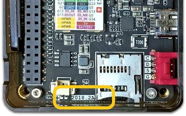
| 2020.3 | Battery capacity changed from 150mAh to 110mAh |
| 2019.7 | TN screen changed to IPS screen |
| 2019.6 | MPU9250 changed to MPU6886+BMM150 |
| 2017.12 | MPU6050+MAG3110 changed to MPU9250, IP5306 connected to I2C bus |
| 2017.9 | First release |