CardputerZero
Work in progress
This product's packaging and software development are not yet complete. Final features and documentation are subject to change. We appreciate your understanding.
SKU:C154
Description
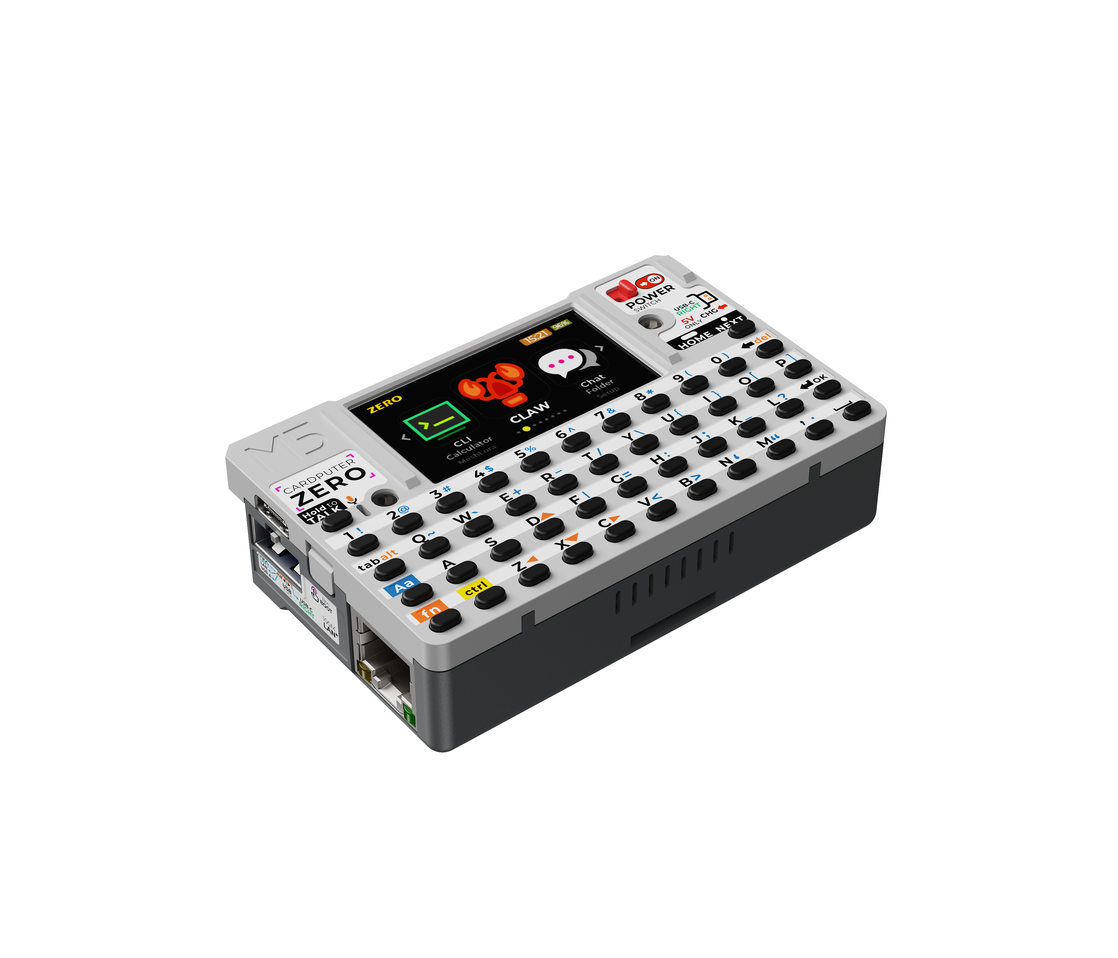
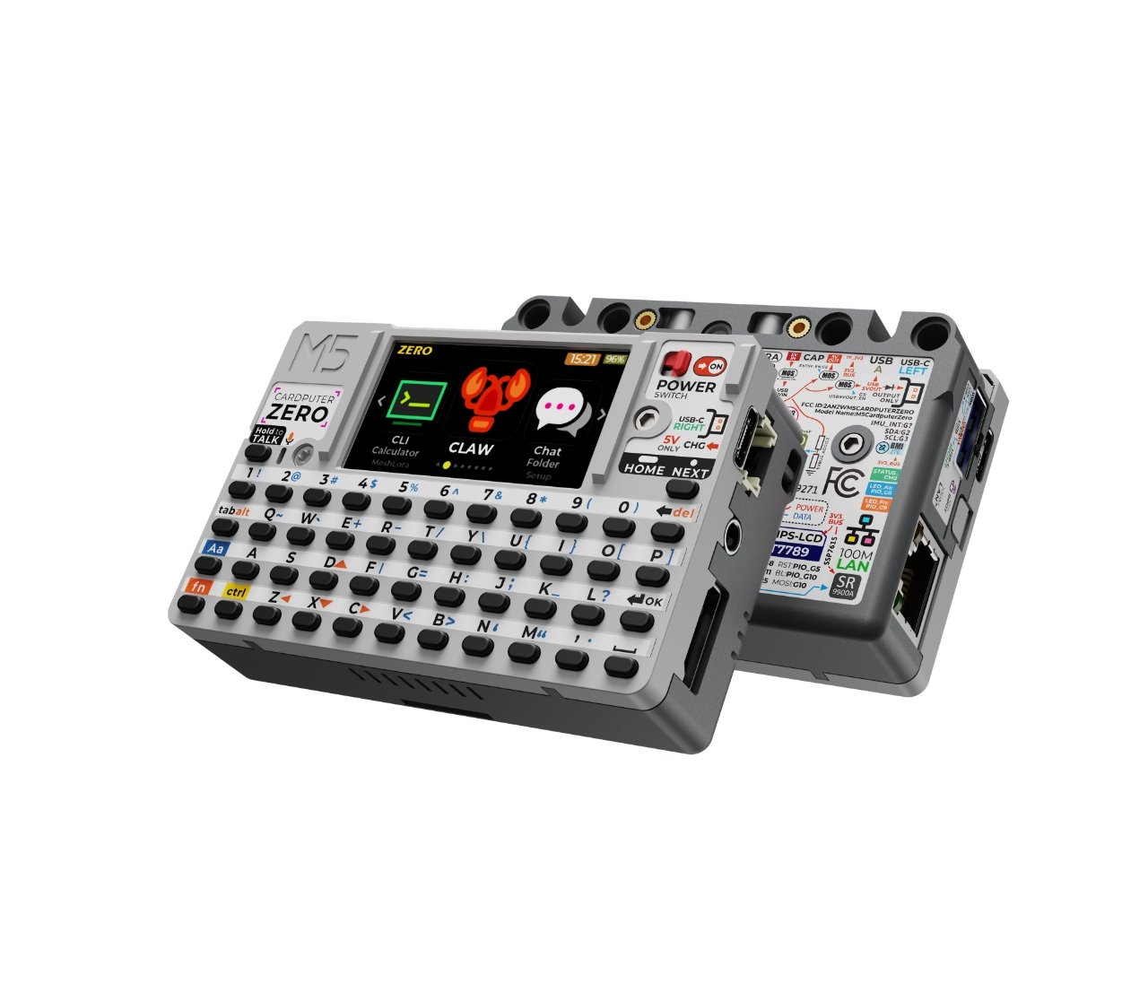
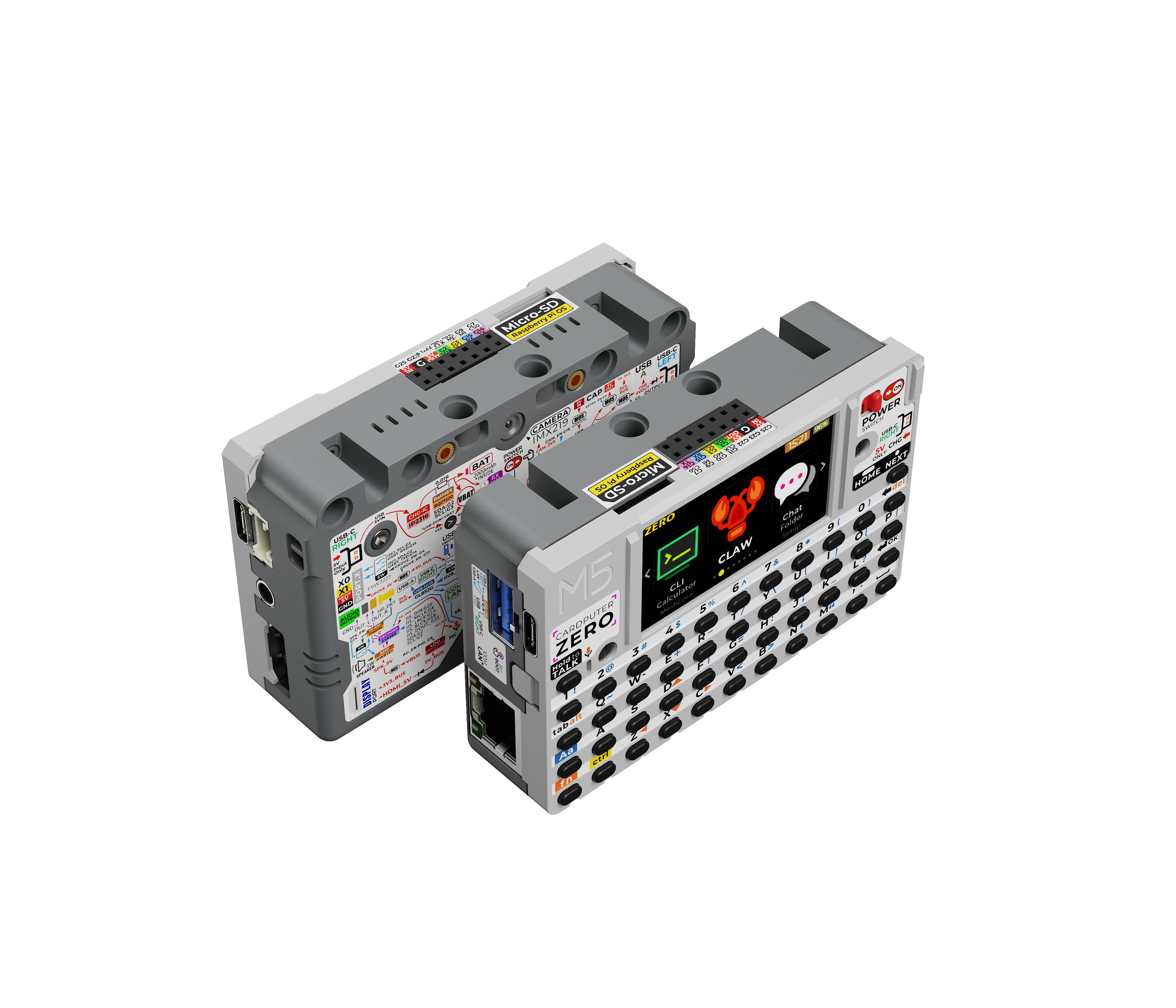
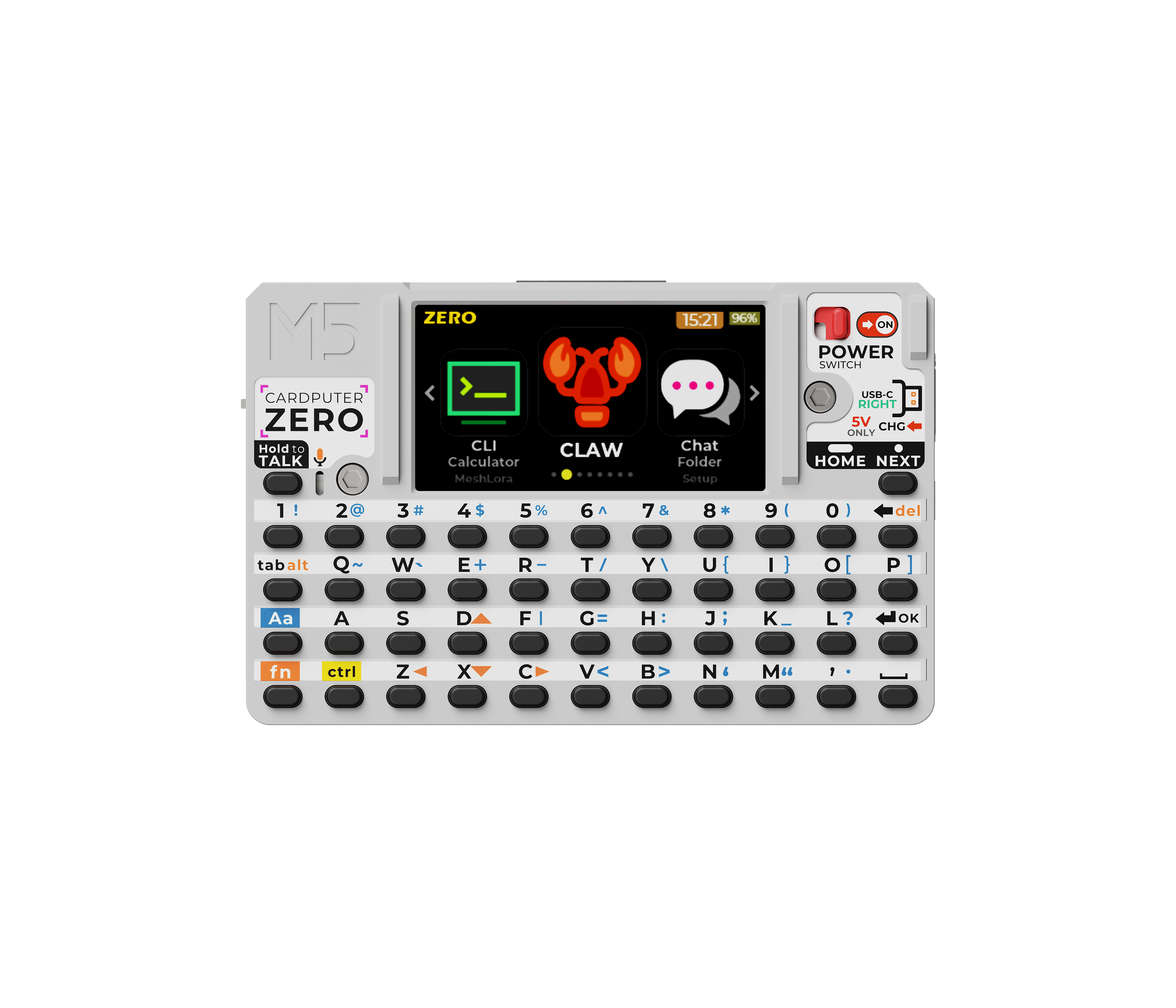
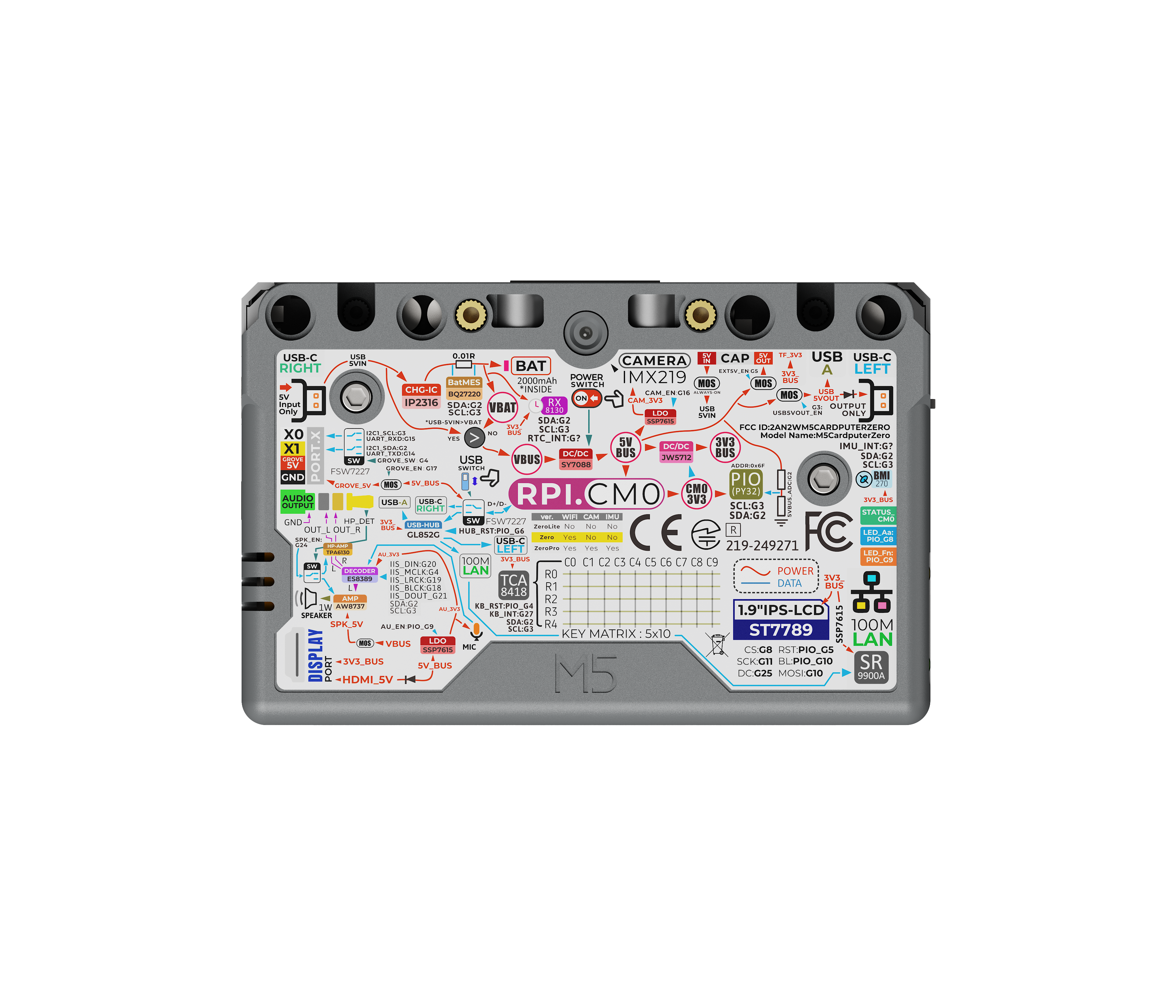
CardputerZero is a pocket-sized Linux personal computer designed for makers and developers, built on the Raspberry Pi CM0 platform. It integrates a quad-core Cortex-A53 processor, a 1.9-inch display, a 46-key matrix keyboard, an 8MP camera, an IMU, and an RTC, delivering a near-complete development terminal experience in a handheld form factor. It also features Wi-Fi, Bluetooth, Ethernet, microSD, a switchable Host/Slave USB architecture, and modular expansion capabilities via I2C/UART/SPI/GPIO. Combined with audio/video codec support and a battery-powered design, it enables an all-in-one solution for on-the-go development, edge data collection, and multimedia interaction. Typical use cases include: mobile penetration testing and operations terminals, IoT device debugging and field deployment, portable AI/vision prototyping, maker project development, and outdoor data collection with rapid human-machine interaction.
Features
- Core Performance:
- Raspberry Pi Compute Module 0 (CM0)
- RP3A0 (BCM2837), Quad-core Cortex-A53 @ 1 GHz
- 512 MB LPDDR2
- Human-Machine Interface:
- 1.9" LCD, resolution 320 x 170
- 46-key matrix keyboard
- IMX219 8MP camera
- BMI270 IMU + BMM150 magnetometer
- IR transmitter + receiver
- Network Connectivity:
- 2.4 GHz Wi-Fi 802.11 b/g/n
- 10/100M Ethernet
- USB Expansion:
- Supports Host / Slave mode switching
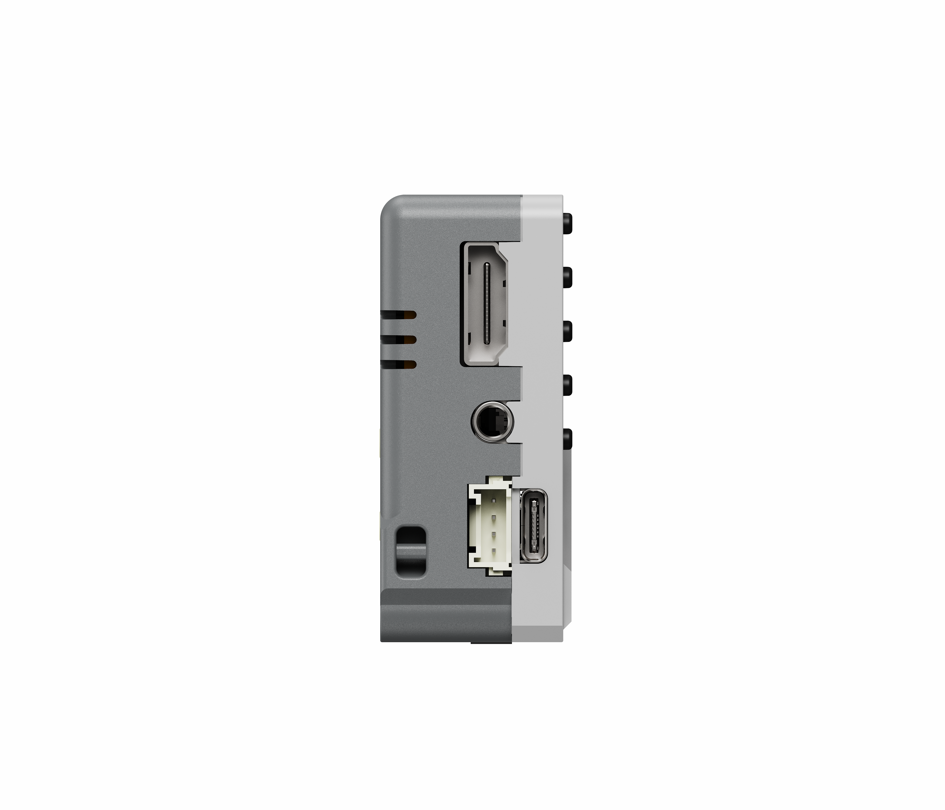
- 1x USB-A 2.0
- 2x USB Type-C 2.0, with USB OTG support on the right-side port
- External Expansion:
- 1x microSD card slot
- 1x HY2.0-4P port with switchable I2C / UART
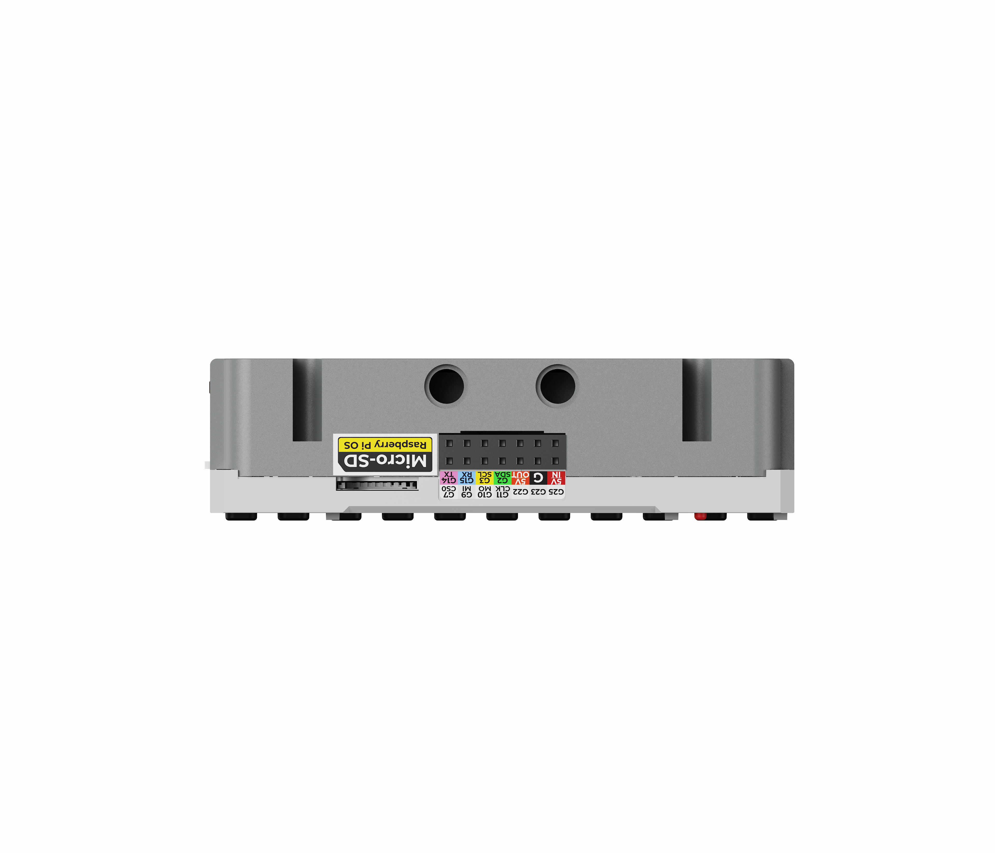
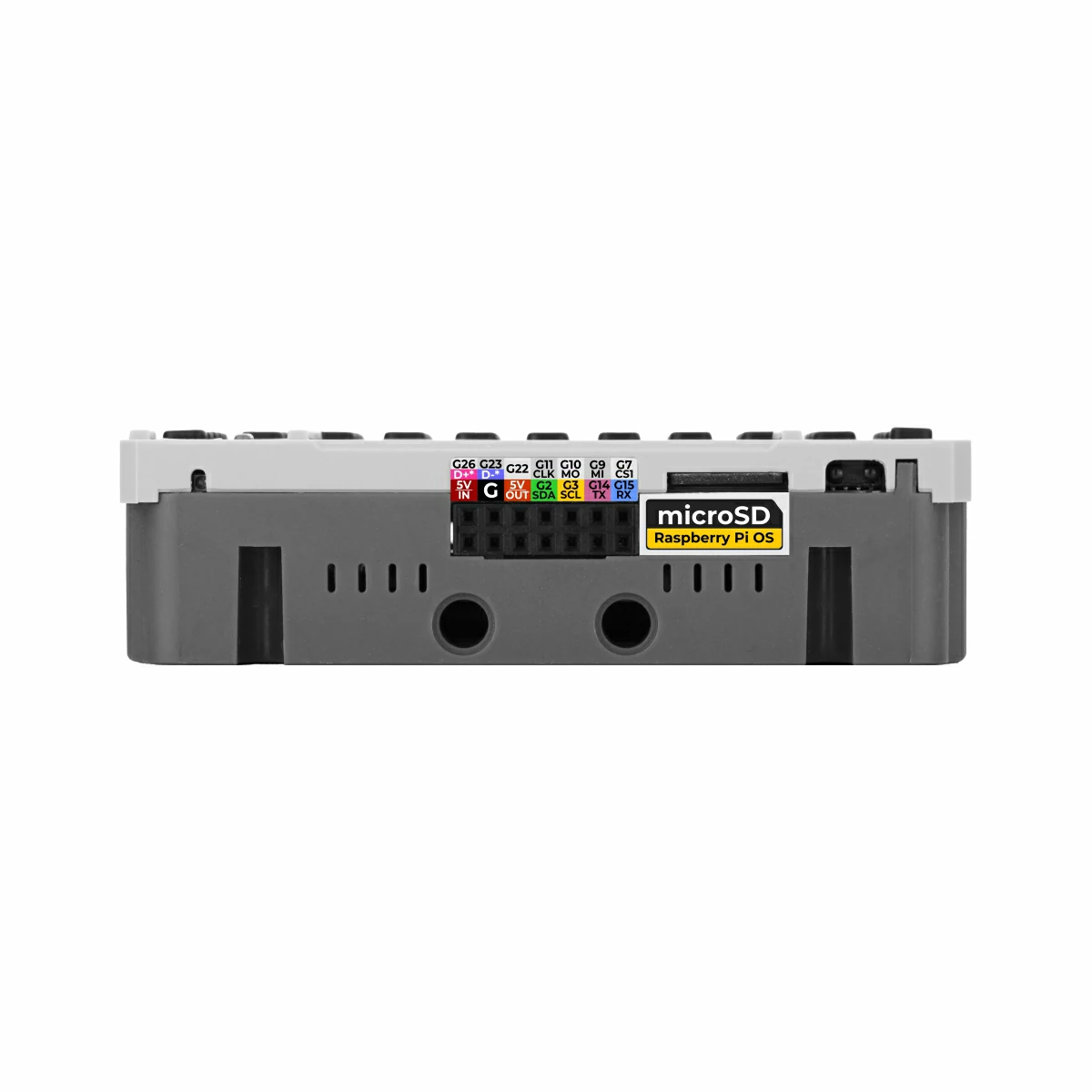
- EXT 2.54-14P expansion bus with SPI, UART, I2C, USB, and GPIO support
- Audio & Video:
- ES8389 audio codec
- 1x MEMS microphone
- 1W @ 8Ω speaker
- 3.5mm TRRS audio input/output jack
- Supports 1080P 30fps video output and codec
- Power Management:
- Built-in DC 3.7V@1750mAh lithium battery with integrated NTC
- BQ27220YZFR battery gauge
- RX8130CE RTC
Includes
Product Note
The standard CardputerZero includes a 32GB microSD card, whereas the CardputerZero-Lite does not include a microSD card and requires one to be purchased separately.
CardputerZero (SKU:C154)
- 1 x CardputerZero
- 1 x 32GB microSD Card
CardputerZero-Lite (SKU:C155)
Applications
- Operations terminal
- IoT device debugging
- Portable AI / vision prototyping
- Maker project development
Specifications
| Specification | Parameter |
|---|
| Core | Raspberry Pi Compute Module 0 (CM0) |
| CPU | RP3A0 (BCM2837), Quad-Core Cortex-A53 @ 1 GHz, ARMv8-A (aarch64) |
| RAM | 512 MB LPDDR2 |
| Storage | microSD |
| Wi-Fi | 2.4 GHz Wi-Fi 802.11 b/g/n |
| Ethernet | 10/100M Ethernet, SR9900A USB 2.0 to Ethernet chip |
| Display | 1.9" LCD @ ST7789v3, resolution 320 x 170 |
| Camera | IMX219 CSI 4-Lane 8MP (3280 x 2464) |
| IMU & Magnetometer | BMI270 + BMM150 |
| RTC | RX8130CE |
| Infrared | IR transmitter + receiver |
| Keyboard | 46-key matrix keyboard |
| Audio Codec | ES8389 |
| Microphone | 1x MEMS microphone |
| Speaker | AW8737A speaker amplifier + 1W @ 8Ω speaker |
| Audio Interface | 3.5mm TRRS audio input/output jack, recommended for 35Ω impedance headphones |
| Video Output | 1x digital HD audio/video output, supports 1080P 30fps |
| Video Codec | H.264 / MPEG-4 1080P 30fps decoding, H.264 1080P 30fps encoding |
| Expansion Interface | EXT 2.54-14P expansion bus, 1x HY2.0-4P port (switchable I2C / UART, maximum 5V output current < 500mA) |
| USB Ports | 1x USB-A 2.0, 2x USB Type-C 2.0, supports Host / Slave switching and USB OTG |
| USB Hub Chip | GL852G-OHY60 USB 2.0 Hub |
| Battery Gauge | BQ27220YZFR |
| Idle Power Consumption | 2.5W |
| Built-in Battery | DC 3.7V @ 1750mAh with integrated NTC |
| Power Supply | Recommended 5V @ 2A for power/charging |
| Product Size | 84.0 x 54.0 x 23.1mm |
| Product Weight Work in | progress |
| Package Size | Work in progress |
| Gross Weight | Work in progress |
Learn
Cap Expansion Notice
When CardputerZero is used with the Cap series products, hot-swapping is not supported. Hot-swapping may cause the device to malfunction. Power off the device before inserting or removing a Cap module.
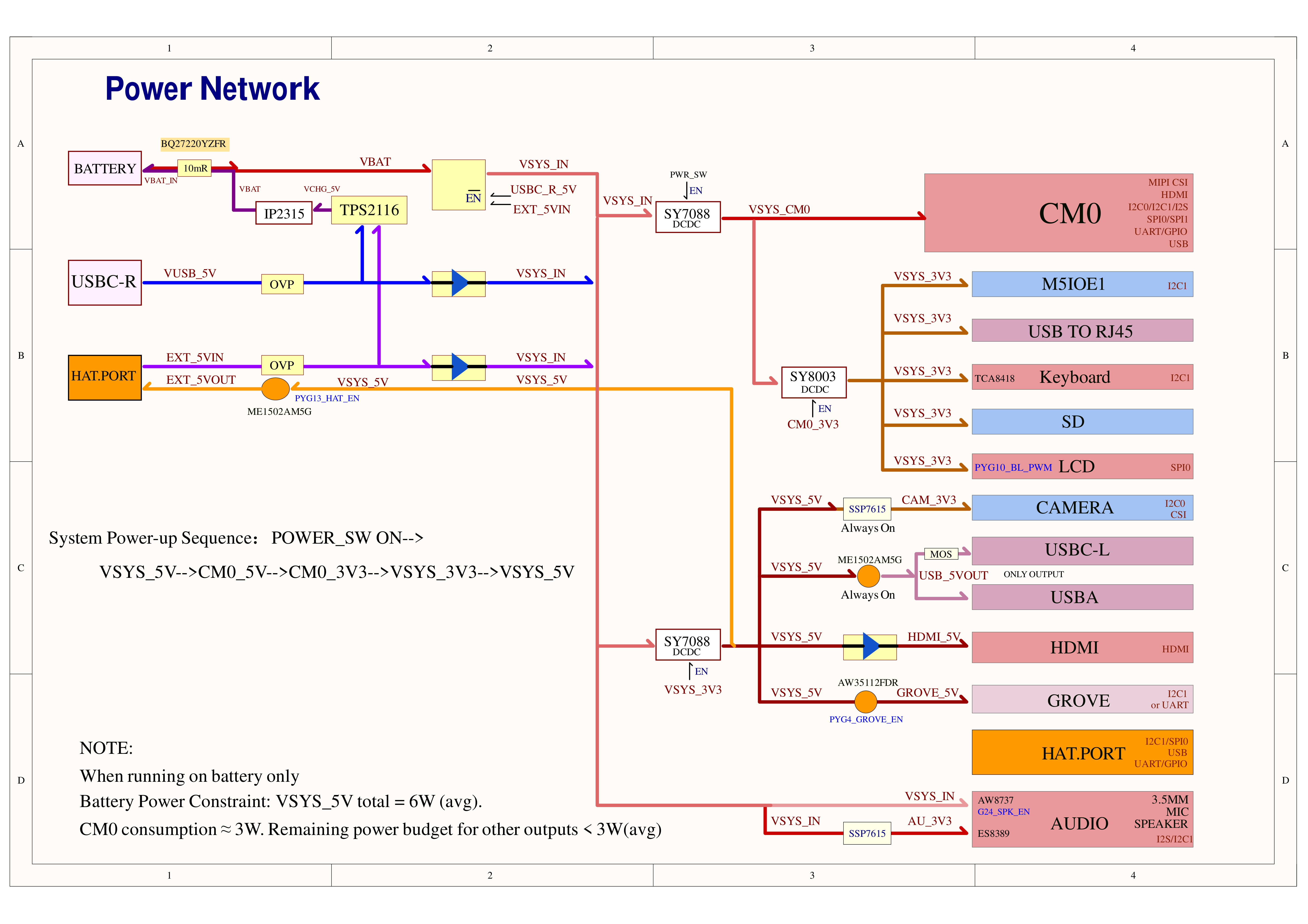
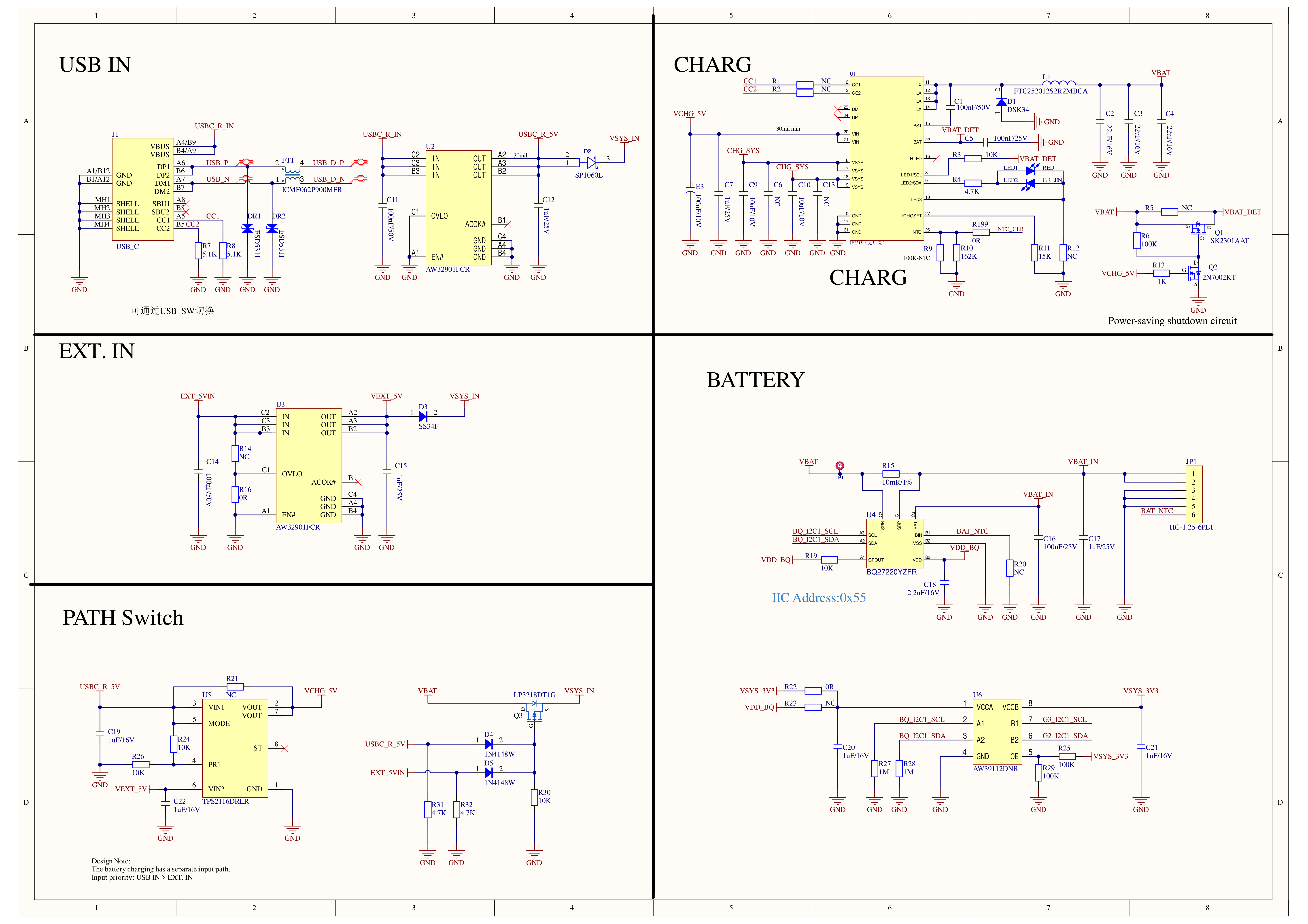
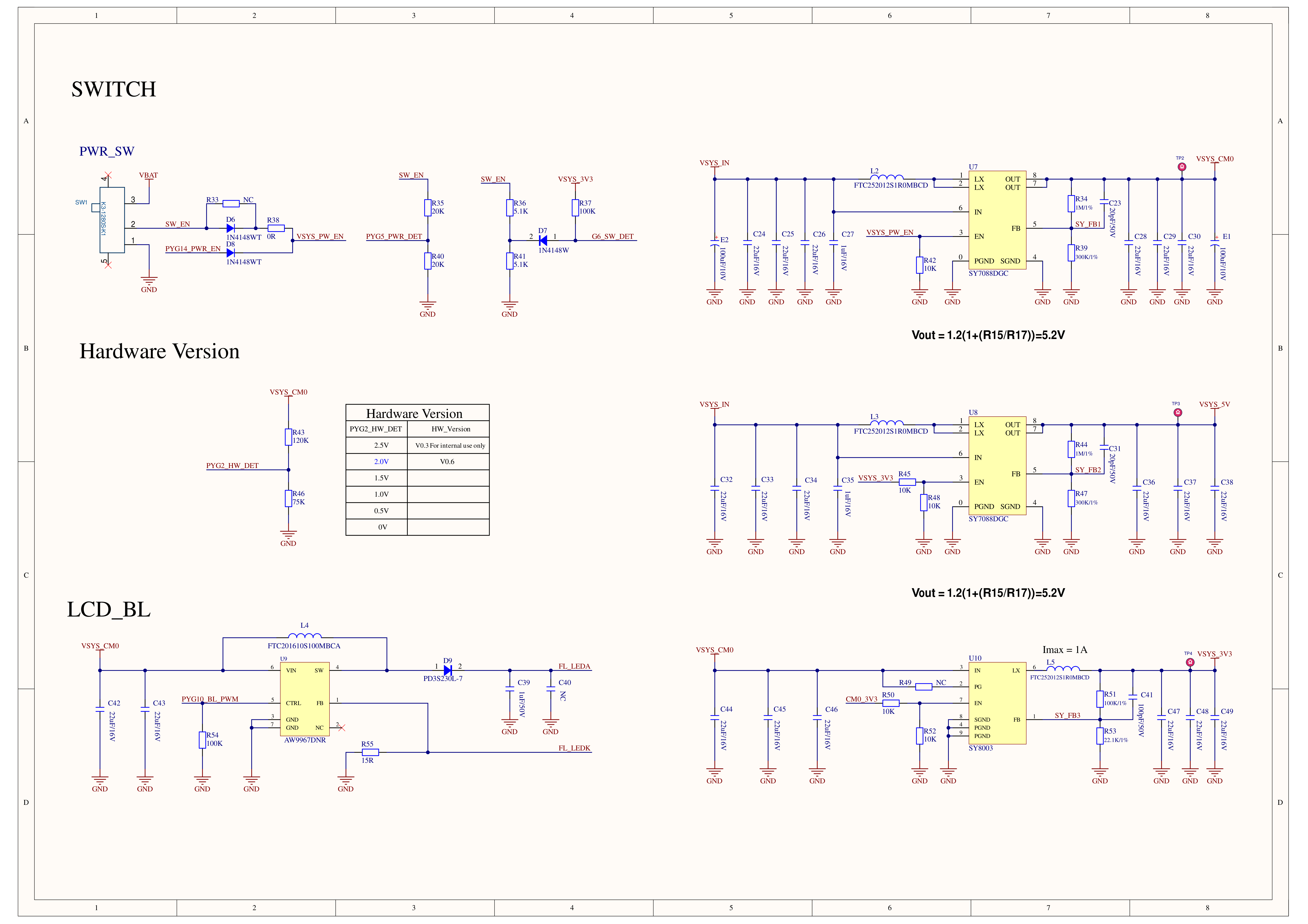
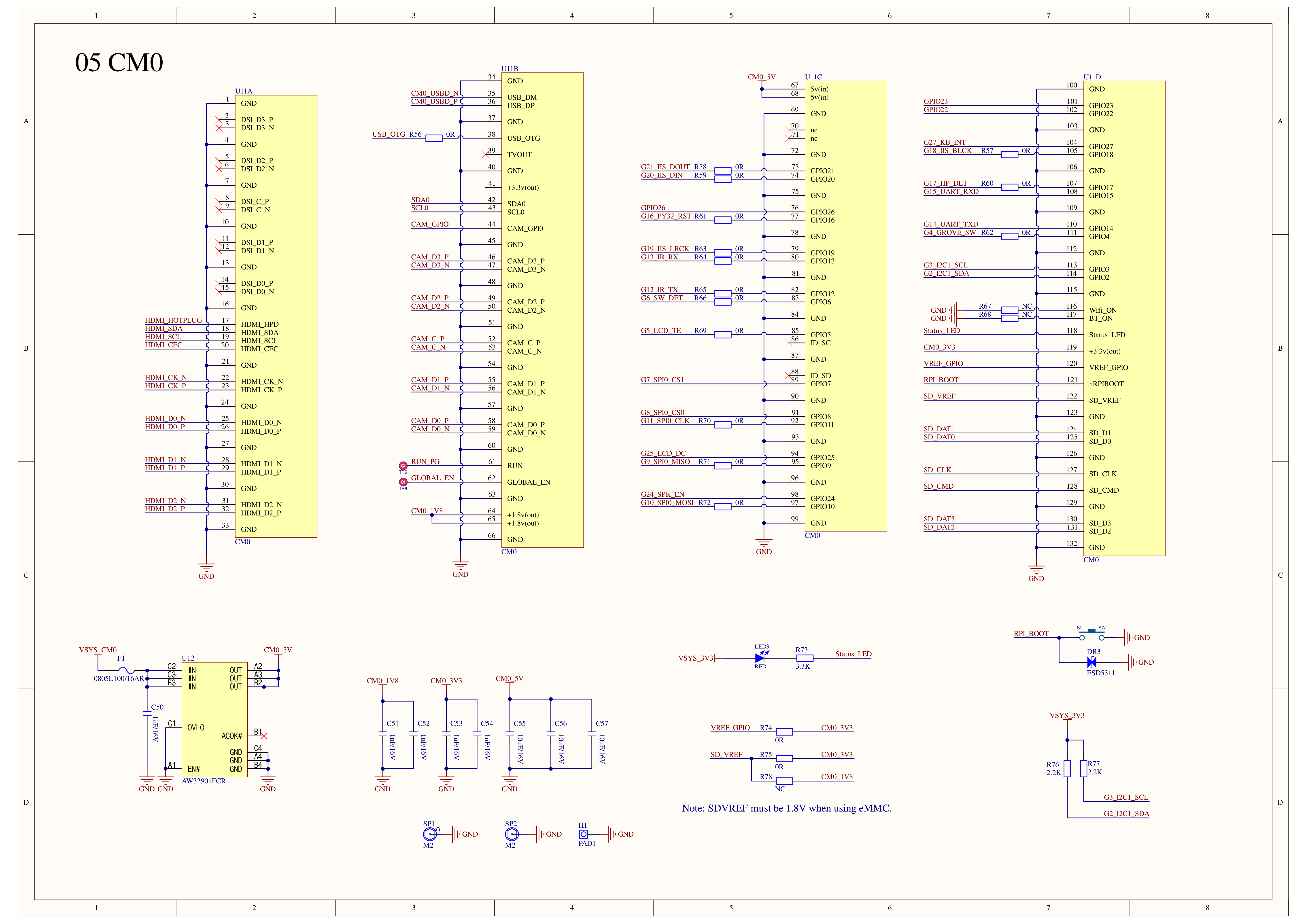
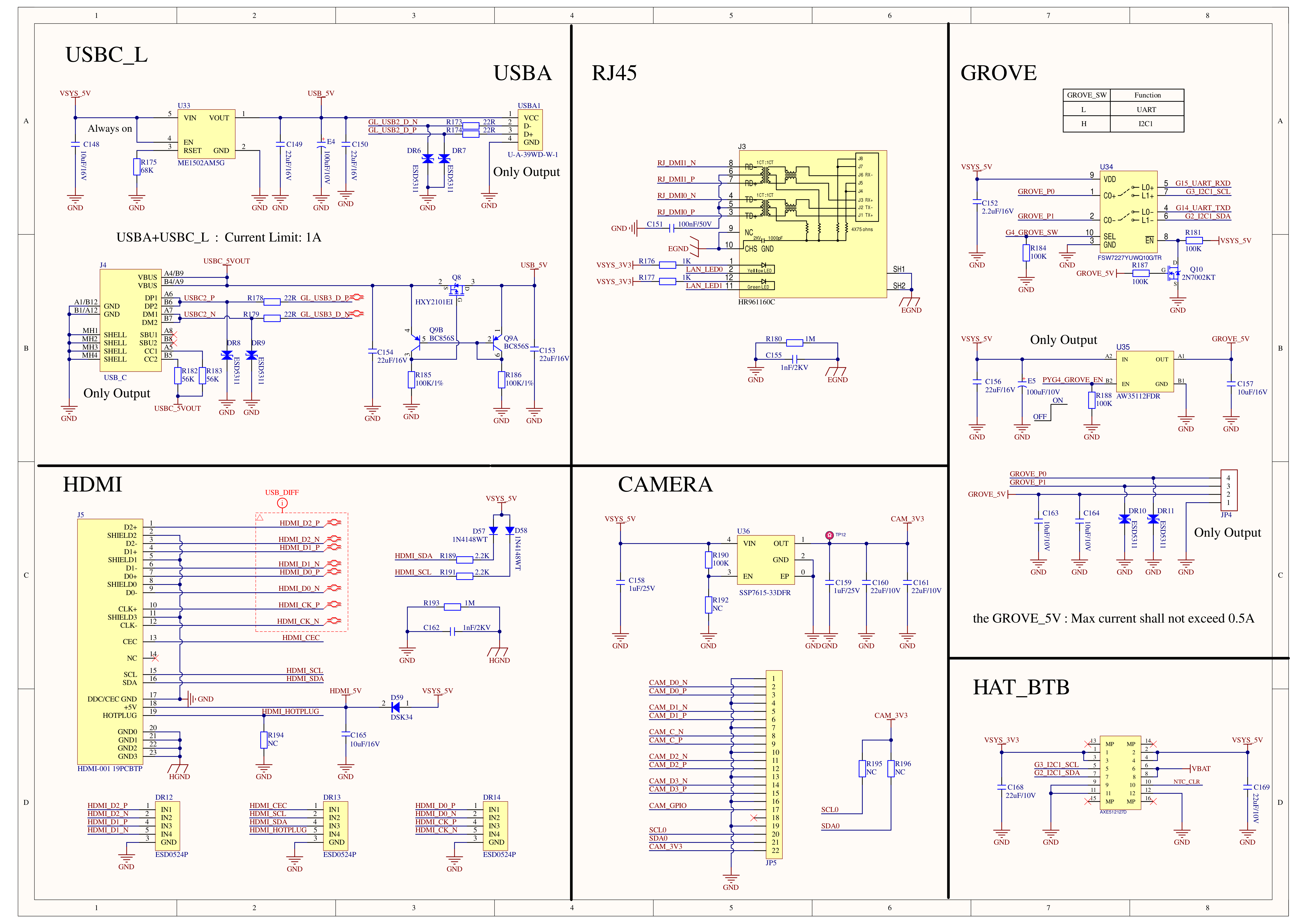
Schematics
PinMap
Display
| CM0 | G10 | G11 | G25 | G8 | G5 |
|---|
| ST7789v3 | MOSI | SCLK | DC | CS | TE |
| ST7789v3 | LCD_RST | BL |
|---|
| M5IOE1 | PYG12_LCD_RST | PYG10_BL_PWM |
The display reset is controlled by PYG12_LCD_RST on the M5IOE1 I/O expander, while PYG10_BL_PWM controls the display backlight.
Audio
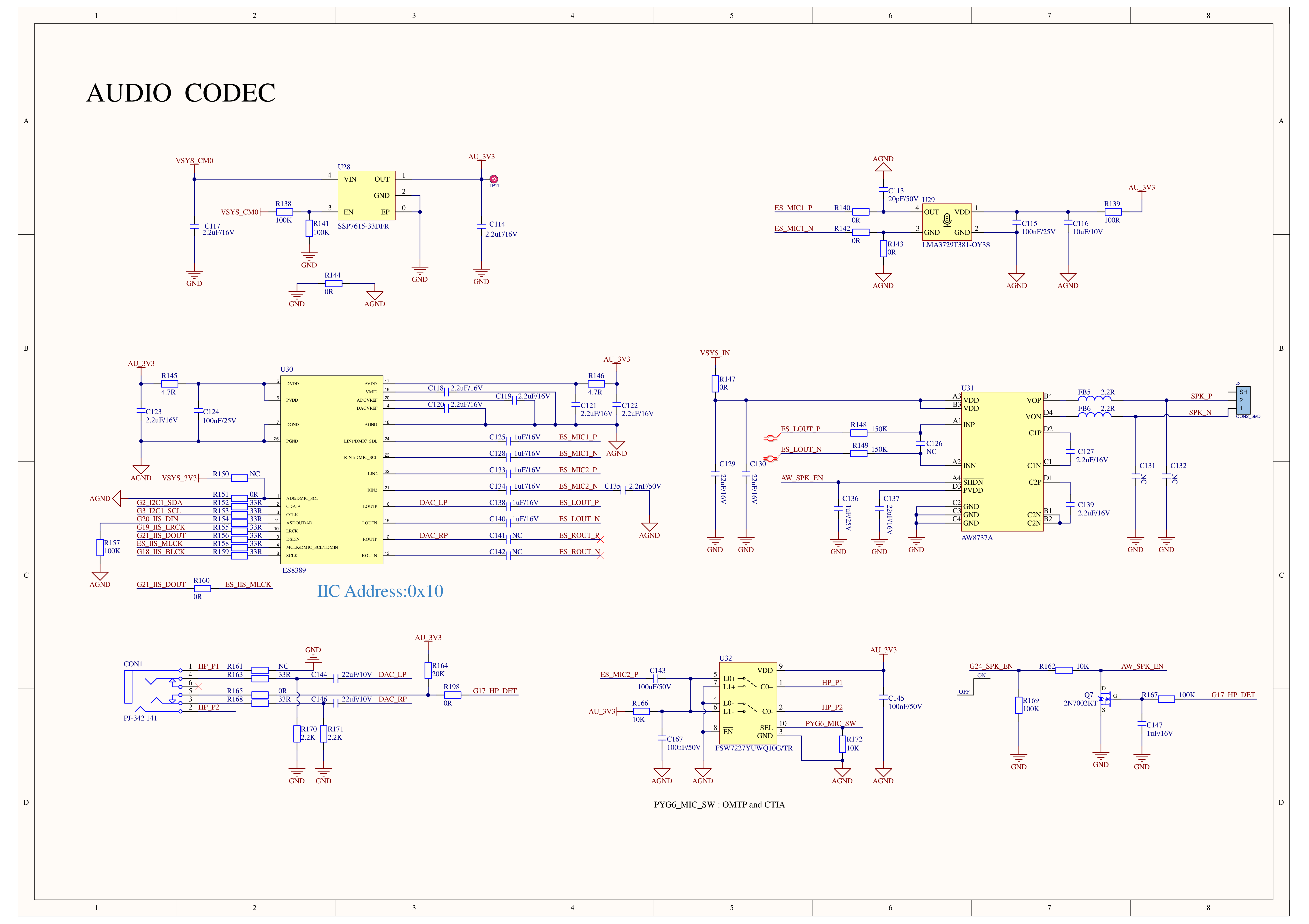
| CM0 | G20_I2S_DIN | G19_I2S_LRCK | G18_I2S_BLCK | G21_I2S_DOUT | G2_I2C1_SDA | G3_I2C1_SCL |
|---|
| ES8389(0x10) | DOUT | LRCK | BCLK | MCLK/DIN | SDA | SCL |
| CM0 | G17 |
|---|
| 3.5mm Headphone | HP_DET |
The 3.5mm audio input/output jack supports plug detection. When HP_DET detects a headphone plug, the system automatically switches the audio output route. When no headphone is connected, the AW8737A speaker amplifier is enabled. The amplifier enable signal is controlled by GPIO G24 on the CM0.
USB 2.0
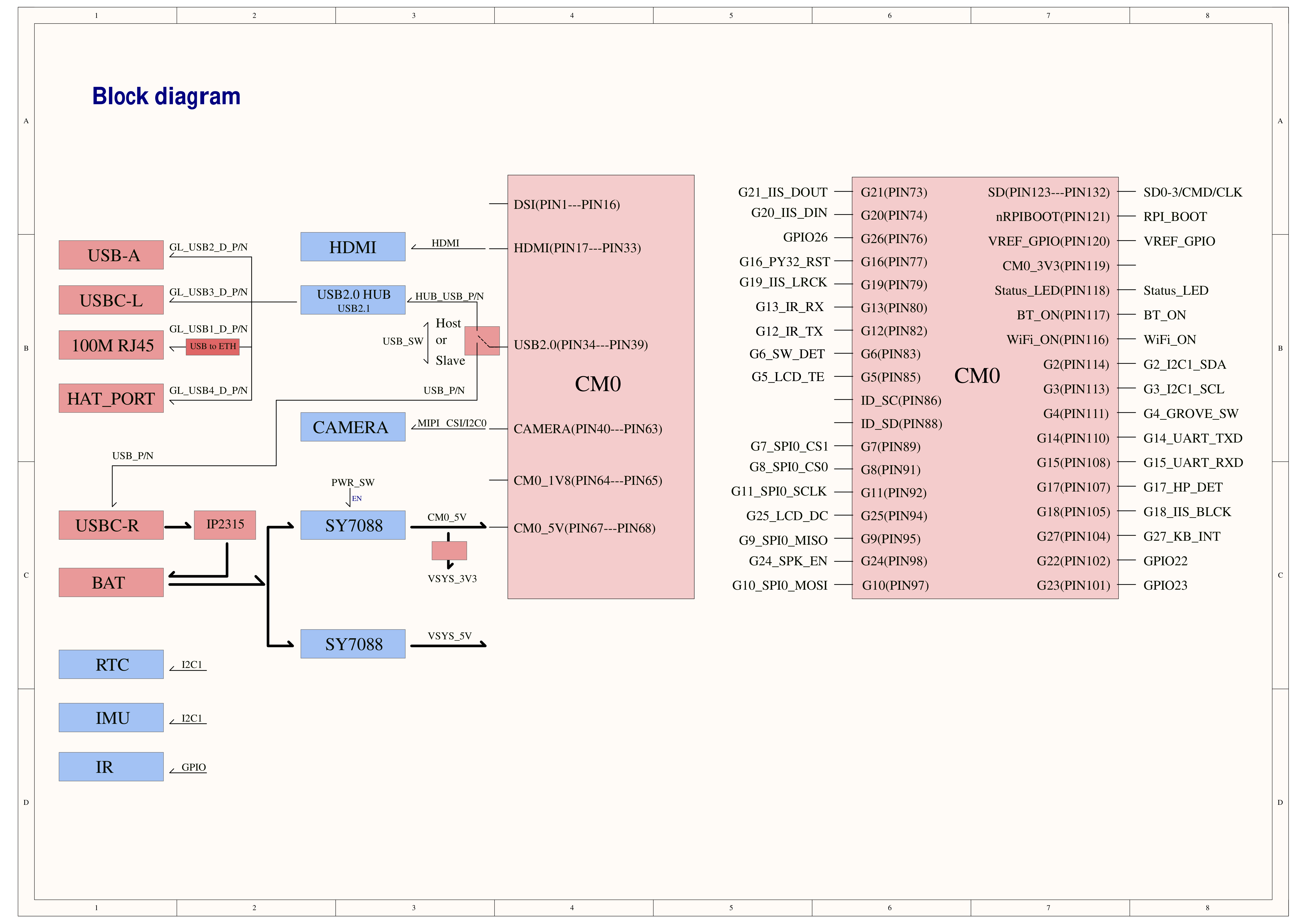
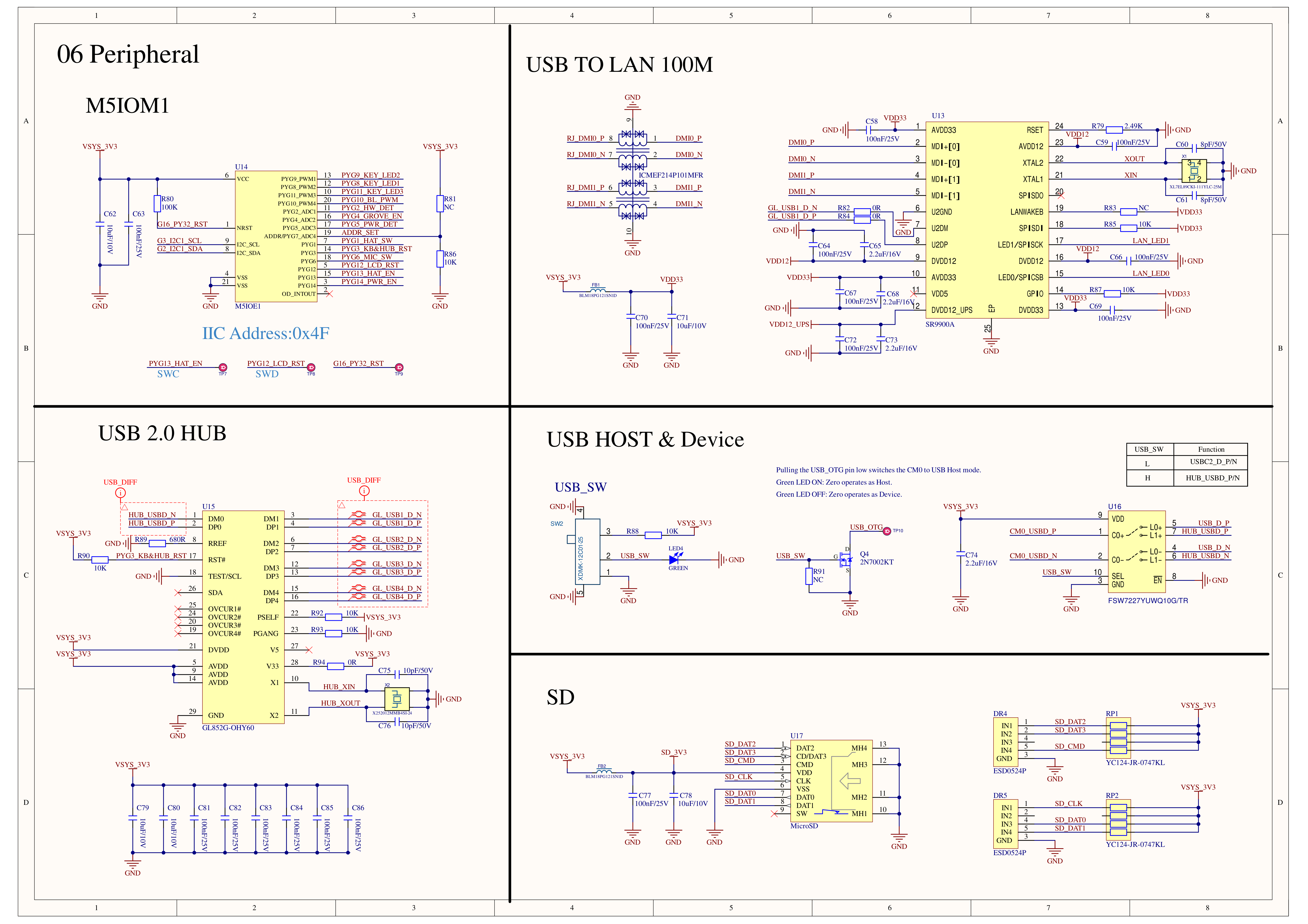
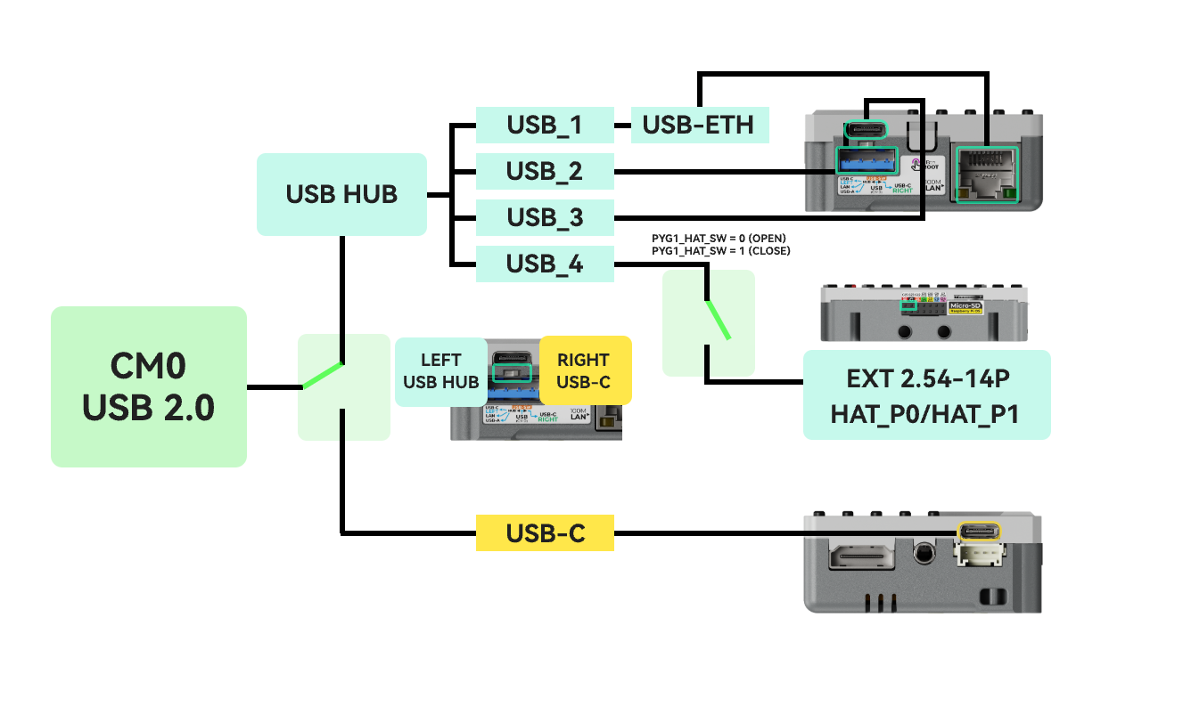
CardputerZero expands the CM0's internal USB interface resources via a USB Hub, enabling multiple USB ports and an Ethernet interface.
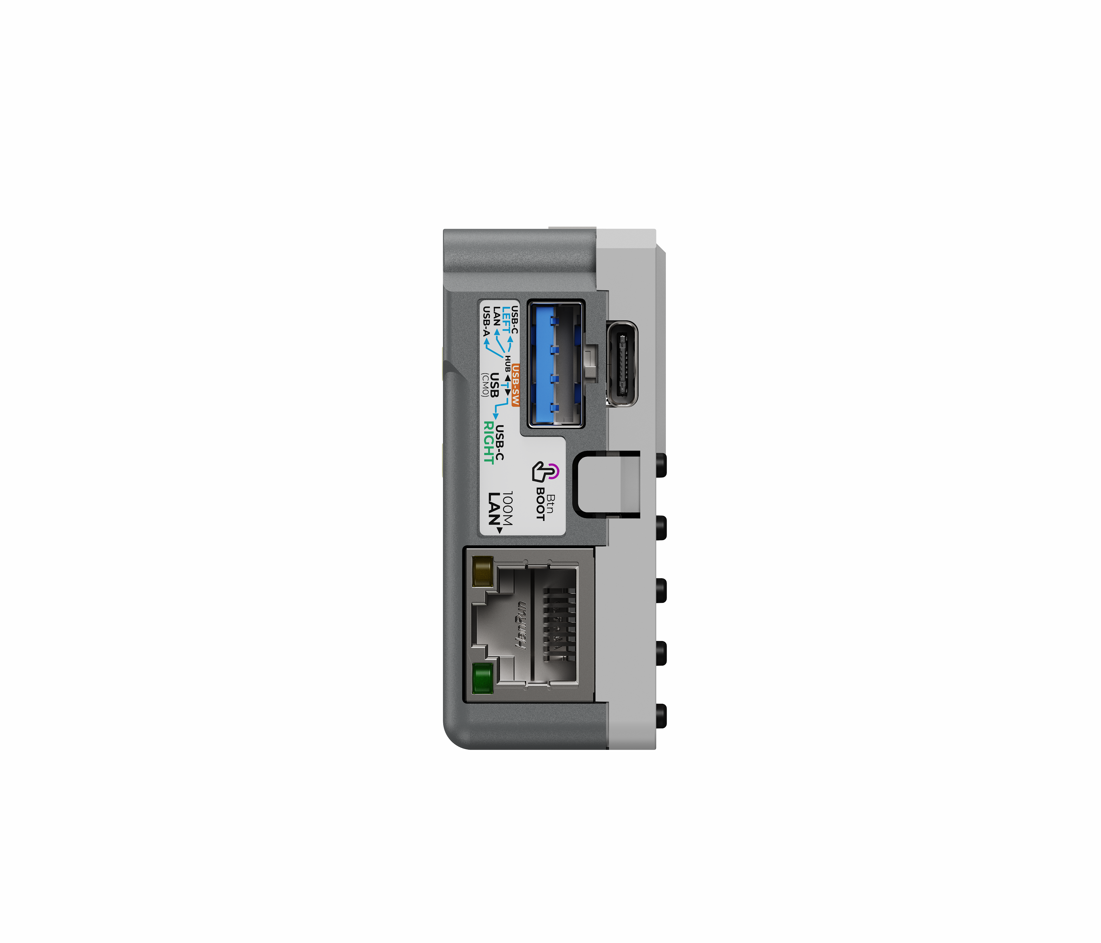
A physical Host / Slave toggle switch is located on the left side of the device. When in Slave mode, the USB Hub chip is disconnected; in this state, the left-side USB-A, USB Type-C ports, the HAT-P0/P1 USB interface on the top EXT 2.54-14P expansion bus, and the Ethernet interface will be unavailable.
- Slave mode:
- CM0 USB is connected to the USB Type-C port on the right side of the device.
- Host mode:
- CM0 USB is connected to the internal USB Hub, which further expands into 4 USB ports.
- USB1 from the Hub is routed through a USB-ETH chip to provide Ethernet functionality.
- USB2 ~ 4 from the Hub are used for the USB-A port, USB Type-C port, and the HAT-P0/P1 USB interface on the top EXT 2.54-14P expansion bus, respectively.
HMI
| CM0 | G2_I2C1_SDA | G3_I2C1_SCL | G27 |
|---|
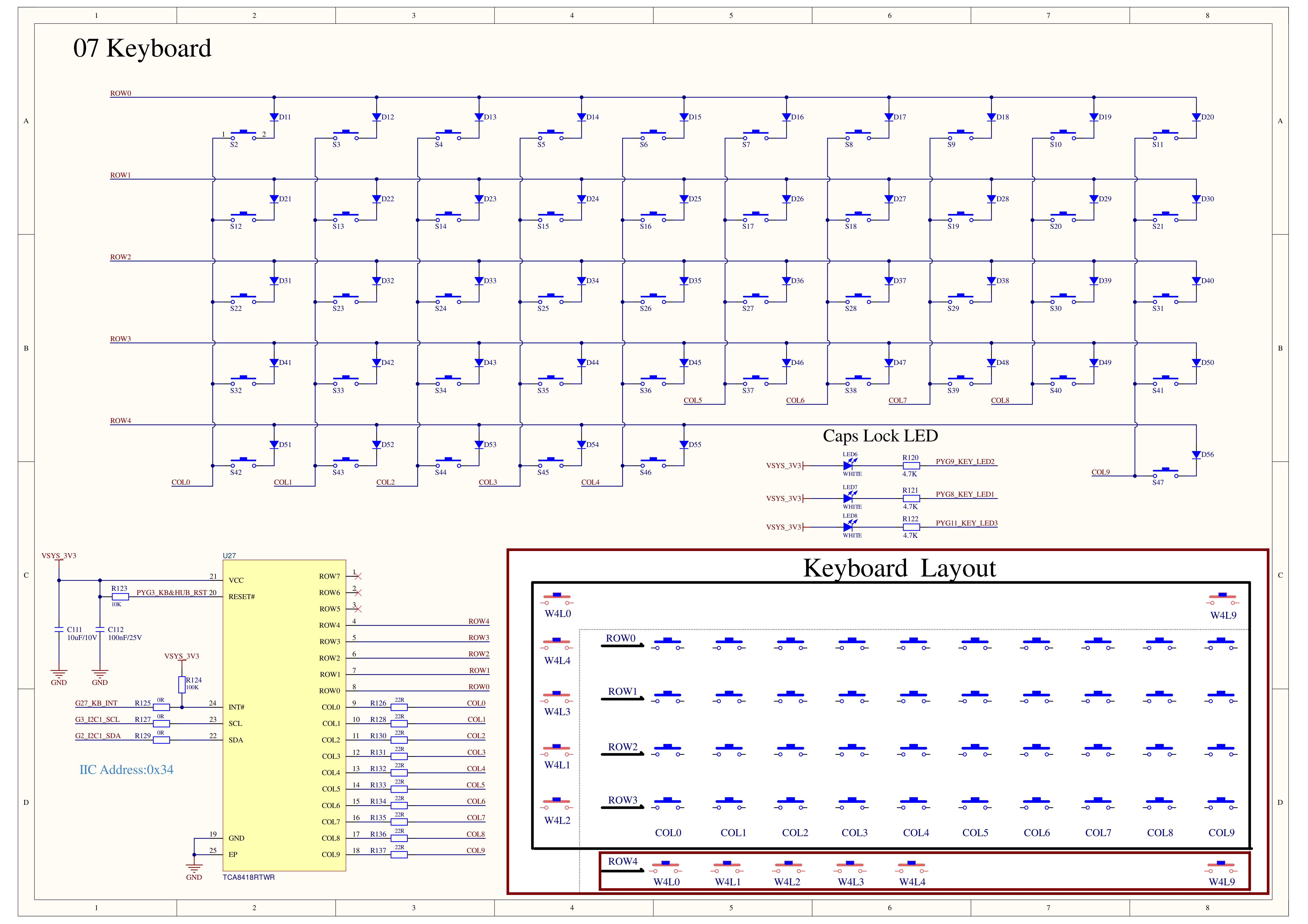
| Keyboard - TCA8418RTWR (0x34) | SDA | SCL | KB_INT |
| IMU - BMI270 (0x68) | SDA | SCL | |
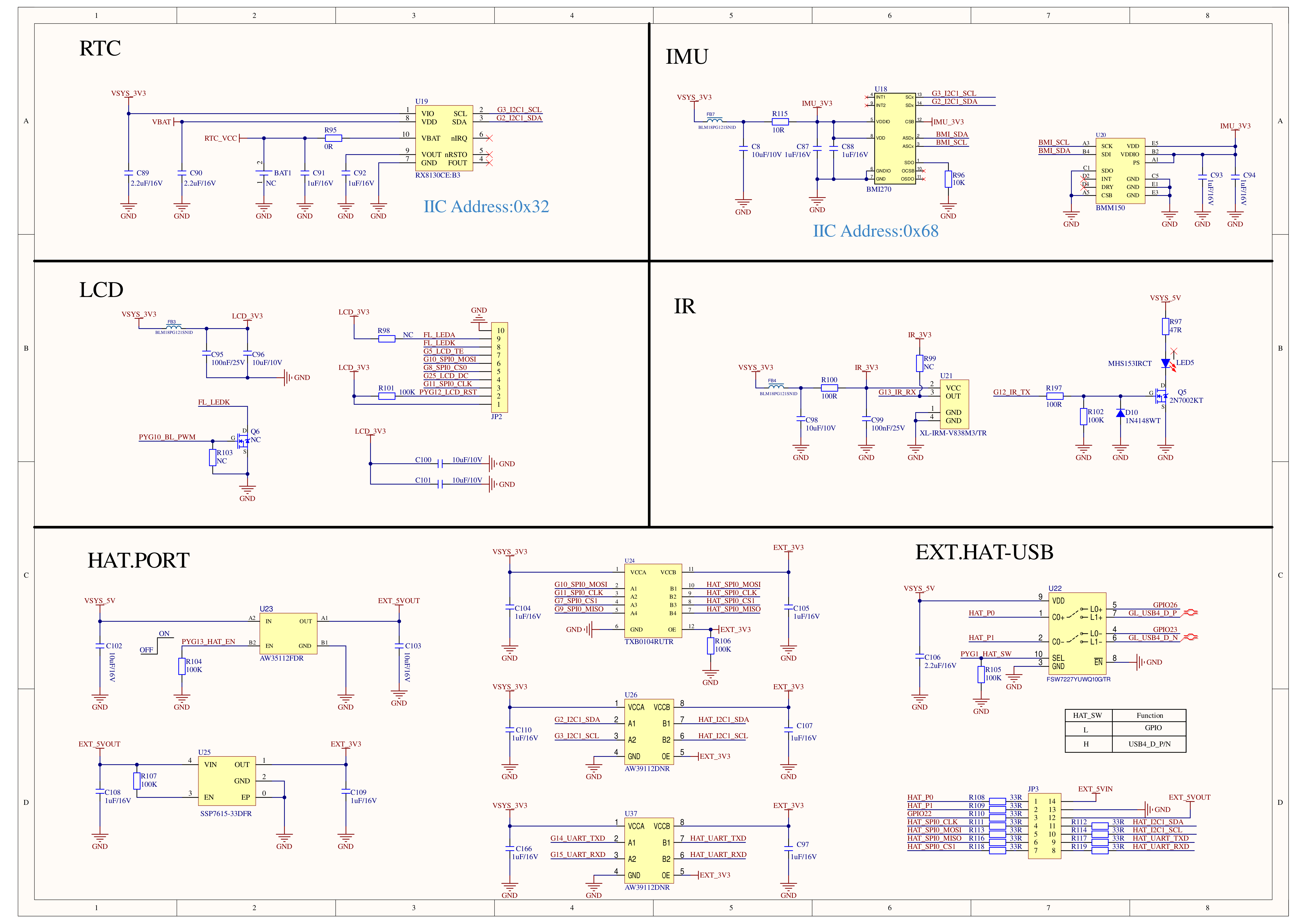
| RTC - RX8130CE (0x32) | SDA | SCL | |
| BMI270 | BMI_SDA | BMI_SCL |
|---|
| BMM150 (0x10) | SDA | SCL |
Power Control
| CM0 | G4 |
|---|
| GROVE_FUNC_SW | I2C/UART_SW |
G6_SW_DET is used to read the switch detection signal.
M5IOE1
| CM0 | G2_I2C1_SDA | G3_I2C1_SCL | G16 |
|---|
| M5IOE1 (0x4F) | SDA | SCL | NRST |
| M5IOE1 | PYG2 | PYG4 | PYG5 | PYG14 |
|---|
| POWER | HW_DET | GROVE_EN | PWR_DET | PWR_EN |
| M5IOE1 | PYG3 | PYG6 |
|---|
| KEYBOARD & USB_HUB | KB_HUB_RST | |
| MIC | | MIC_SW |
PYG3_KB_HUB_RST is the shared reset control signal for the TCA8418RTWR keyboard controller and the GL852G-OHY60 USB Hub.
PYG6_MIC_SW switches the microphone channel of the 3.5mm TRRS interface between the CTIA / OMTP standards.
| PYG6_MIC_SW | Standard |
|---|
| LOW | CTIA |
| HIGH | OMTP |
- HAT P0/P1 Function Switch
| M5IOE1 | PYG1 |
|---|
| SW | PYG1_HAT_SW |
| M5IOE1 | PYG13 |
|---|
| HAT_EN | PYG13_HAT_EN |
PYG13_HAT_EN controls the HAT interface enable state.
| PYG13_HAT_EN | HAT PORT POWER |
|---|
| LOW | OFF |
| HIGH | ON |
- CAPS LOCKS Indicator LEDs
| M5IOE1 | PYG8 | PYG9 | PYG11 |
|---|
| KEY_LED1 | SHIFT_LED | | |
| KEY_LED2 | | FN_LED | |
| KEY_LED3 | | | SYM_LED |
IR TX & RX
| CM0 | G12 | G13 |
|---|
| IR | IR_TX | IR_RX |
HY2.0-4P
| HY2.0-4P | Black | Red | Yellow | White |
|---|
| UART / I2C | GND | 5V | G14_UART_TXD / G2_I2C1_SDA | G15_UART_RXD / G3_I2C1_SCL |
The HY2.0-4P interface function is switched via G4_I2C/UART_SW on the CM0. The default function is UART.
| G4_I2C/UART_SW | GROVE FUNC |
|---|
| LOW | UART |
| HIGH | I2C1 |
The 5V output on the interface is enabled via PYG4_GROVE_EN on the M5IOE1. (Maximum supply current < 500mA)
EXT 2.54-14P
| FUNC | PIN | LEFT | RIGHT | PIN | FUNC |
|---|
| USB4_D_P / G26 | HAT_P0 | 1 | 2 | 5VIN | |
| USB4_D_N / G23 | HAT_P1 | 3 | 4 | GND | |
| G22 | 5 | 6 | 5VOUT | |
| SPI0_CLK | G11 | 7 | 8 | G2 | I2C1_SDA |
| SPI0_MOSI | G10 | 9 | 10 | G3 | I2C1_SCL |
| SPI0_MISO | G9 | 11 | 12 | G15 | UART_RXD |
| SPI0_CS1 | G7 | 13 | 14 | G14 | UART_TXD |
The PYG1_HAT_SW pin on the M5IOE1 I/O expander switches the HAT_P0 and HAT_P1 pins between USB / GPIO functions. The default function is GPIO.
| PYG1_HAT_SW | EXT HAT_P0/P1 FUNC |
|---|
| LOW | GPIO26 / GPIO23 |
| HIGH | USB Hub - USB4 |
Appearance Stickers
Softwares
Quick Start
SDK
coming soon...
Kernel
coming soon...
Product Comparison
| Product Compare | CardputerZero 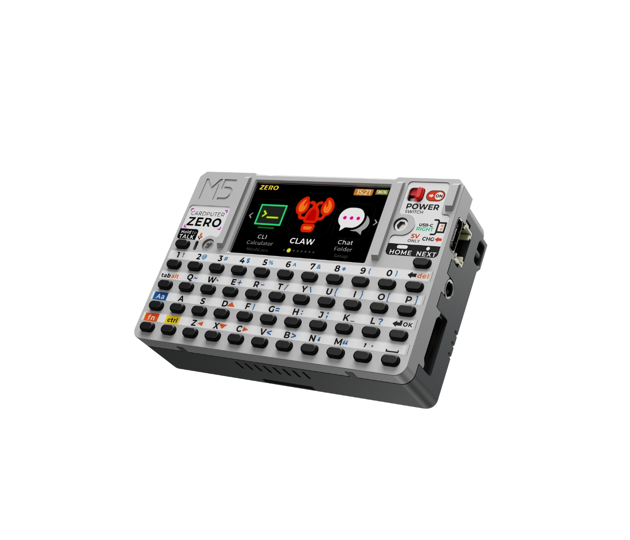 | CardputerZero-Lite  |
|---|
| Core | Raspberry Pi CM0 | Raspberry Pi CM0 |
| Wi-Fi & BT | ✅ | ✅ |
| IR Transmitter + Receiver | ✅ | ✅ |
| 8MP Camera | ✅ | ❌ |
| IMU BMI270 + BMM150 | ✅ | ❌ |
| Includes 32GB microSD | ✅ | ❌ |