

Linux & Edge AI
AI Pyramid
Hardware Control
Applications & Factory Features
LLM-8850 Card
Large Language Models
LLM630 Compute Kit
Module LLM
CoreMP135
Module LLM Serial Communication Pin Switching Tutorial
Pin Switching Description
Because M5Stack's Module series products adopt a stacking design, when multiple products are used simultaneously, pin conflicts may occur. Therefore, Module LLM supports manual switching of communication pins. Since it uses serial communication, the user only needs to adjust the RX and TX pins. Depending on the connected host, you can flexibly choose the appropriate pins.
Pin Switching Position
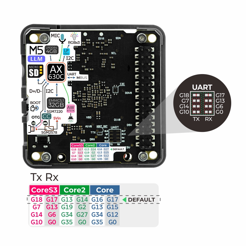
- Pin Mapping
When connecting Module LLM with different hosts, the selectable RX and TX pins are as follows:
| Host | Host RXD | Host TXD |
|---|---|---|
| Core (Basic) | G16/G13/G34/G35 | G17/G15/G12/G0 |
| Core2 | G13/G19/G34/G35 | G14/G2/G27/G0 |
| CoreS3 | G18/G7/G14/G10 | G17/G13/G6/0 |
Pin Switching Operation
- With a CoreS3, the factory configuration uses G18 as the host RX and G17 as the host TX.
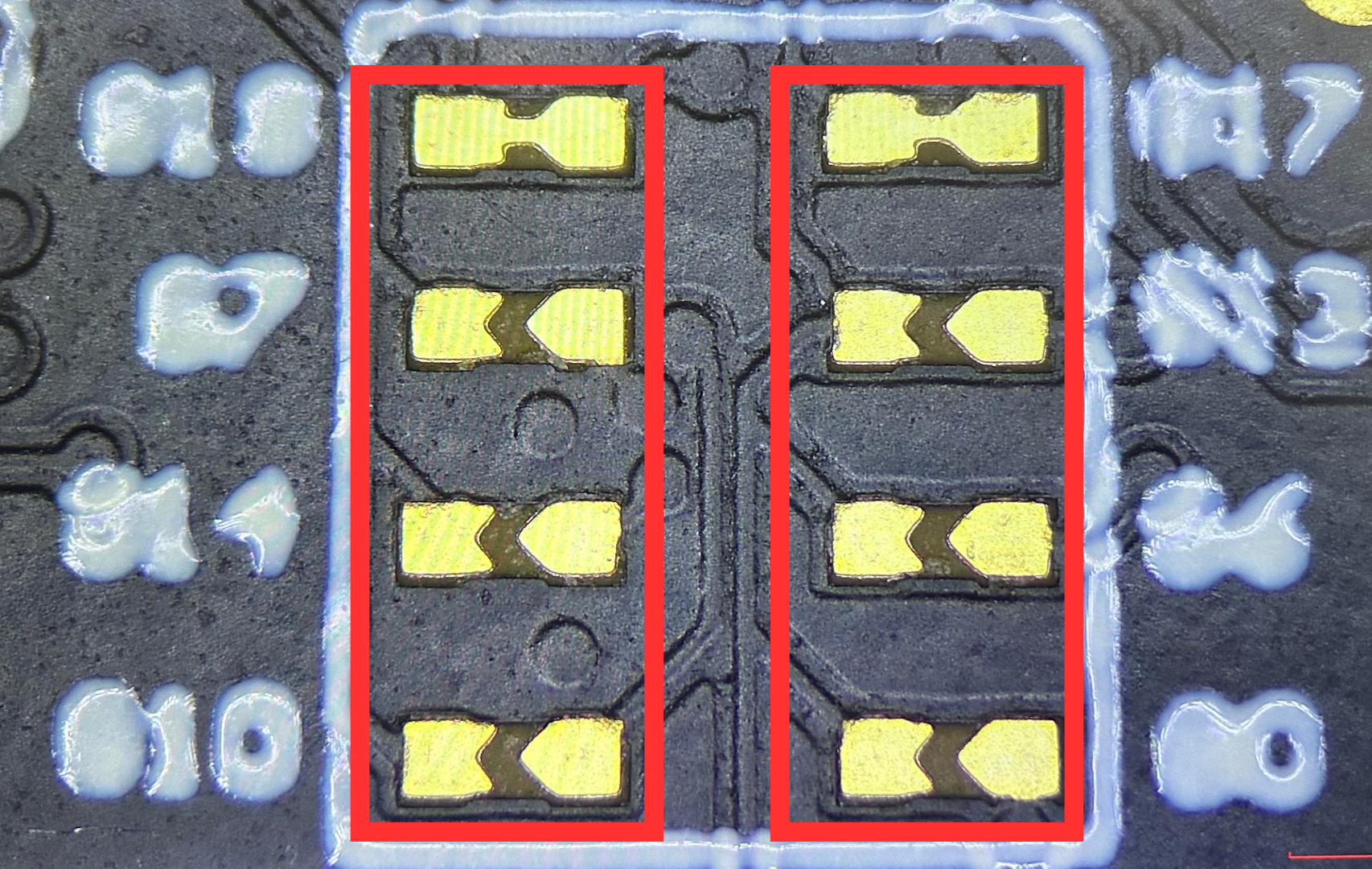
- If you need to switch the RX pin, change it from G18 to G7. Use a blade or other sharp tool to cut the connection between the two solder pads (be careful to avoid injury), and if necessary, use a multimeter to check whether the solder pads have been cut.
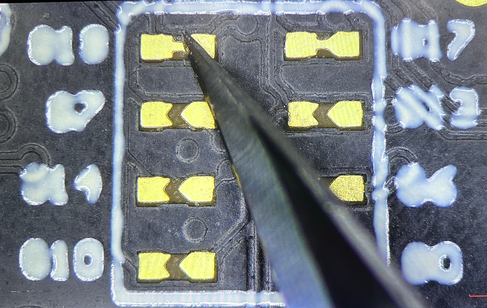
- As shown in the image below, the solder pad connection has been successfully cut:
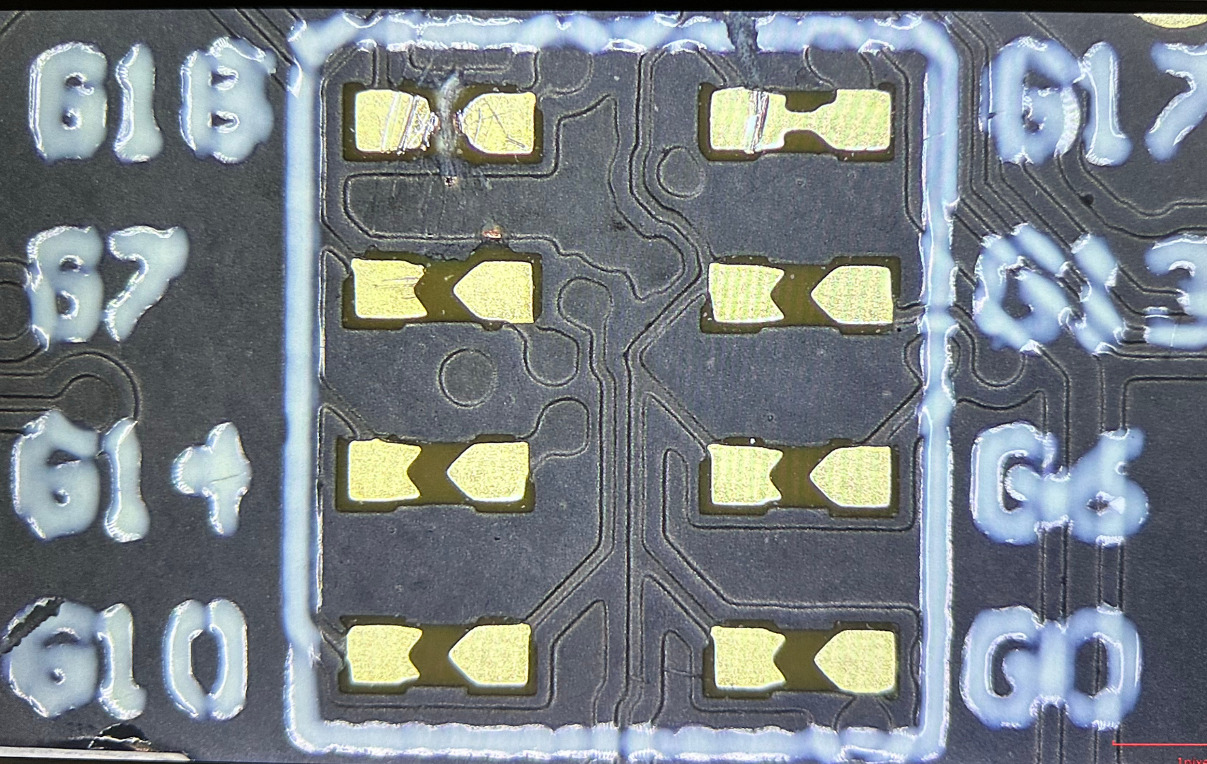
- Then, use a soldering iron to solder the G7 pin.
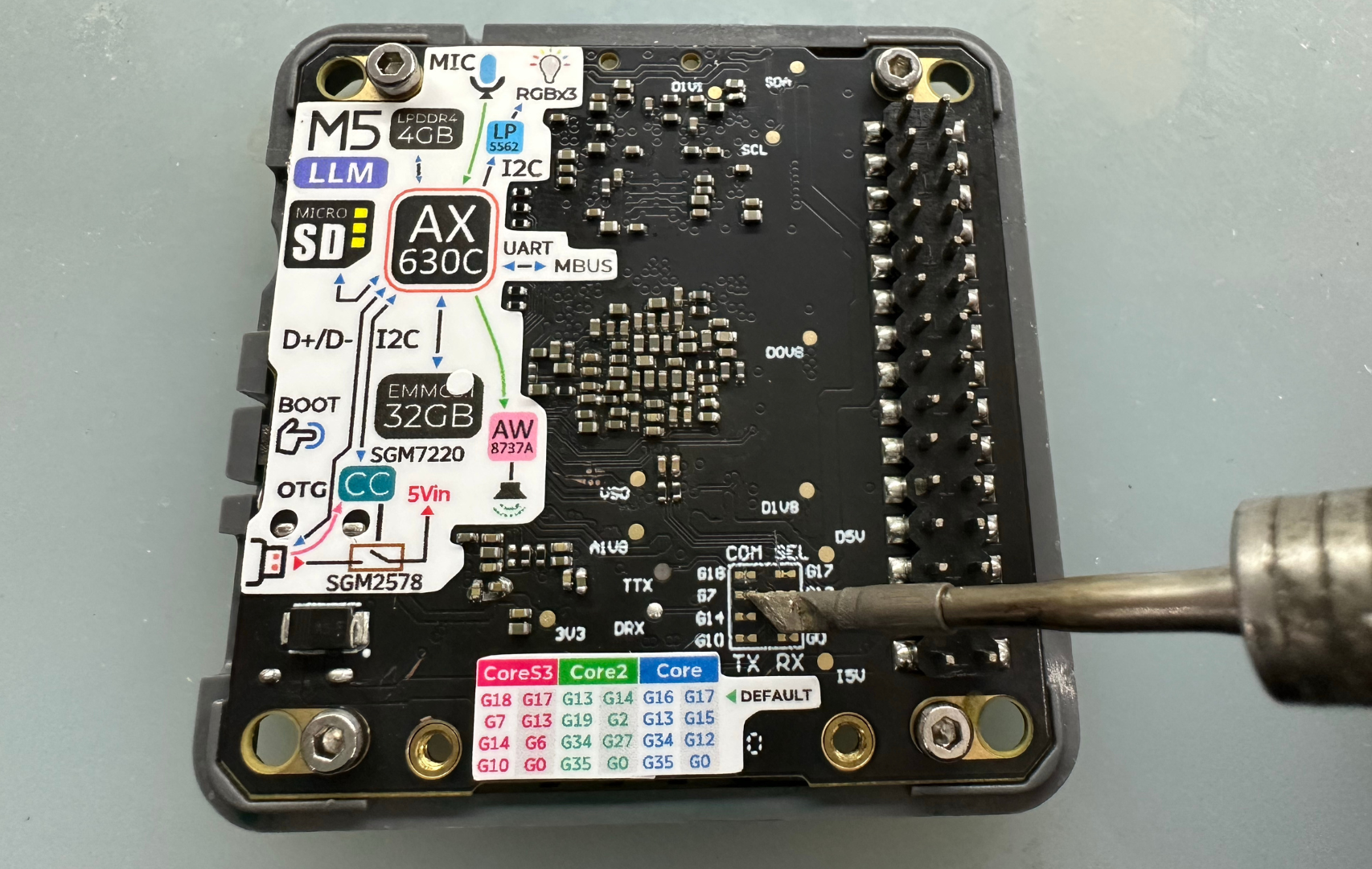
- The soldering result is as follows:
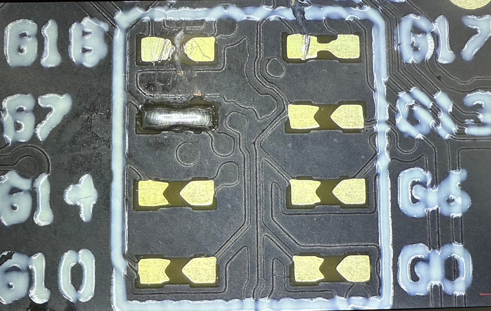
After switching, the CoreS3 uses G7 for RX and G17 for TX. In Arduino, configure the port with Serial2.begin(115200, SERIAL_8N1, 7, 17).
Page Tools