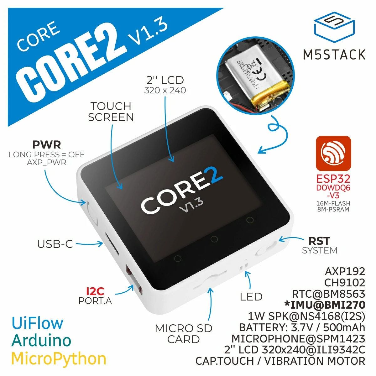
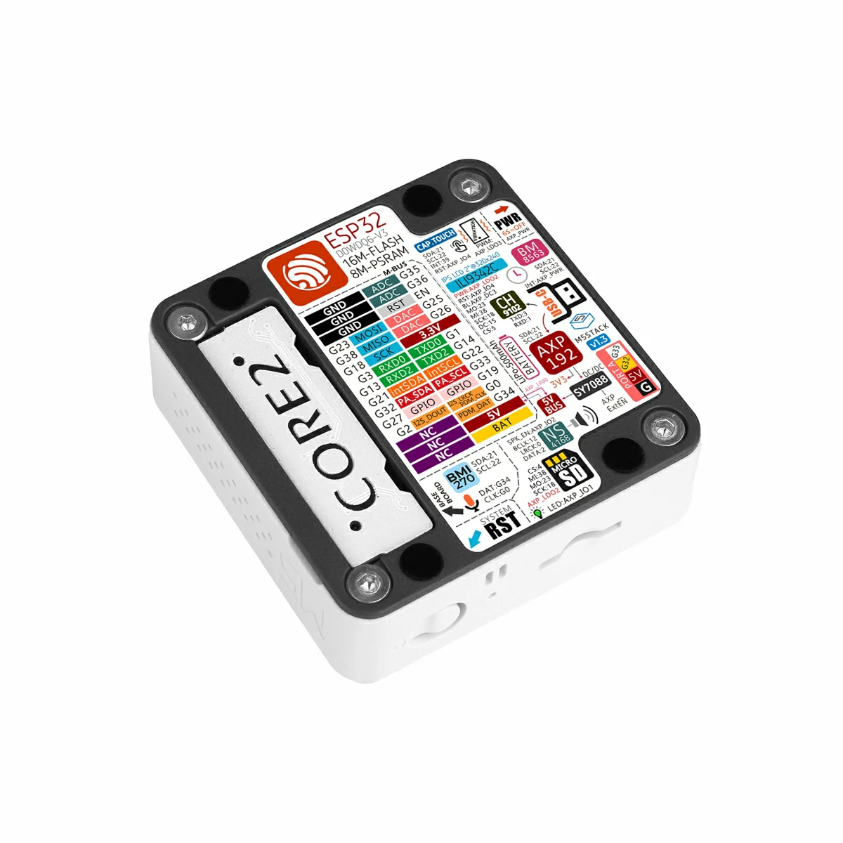
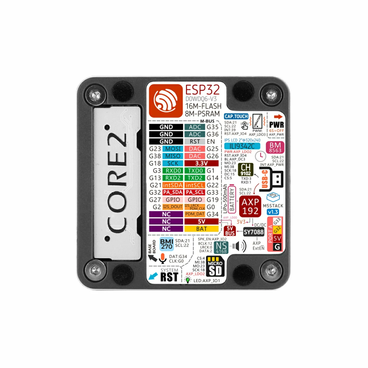
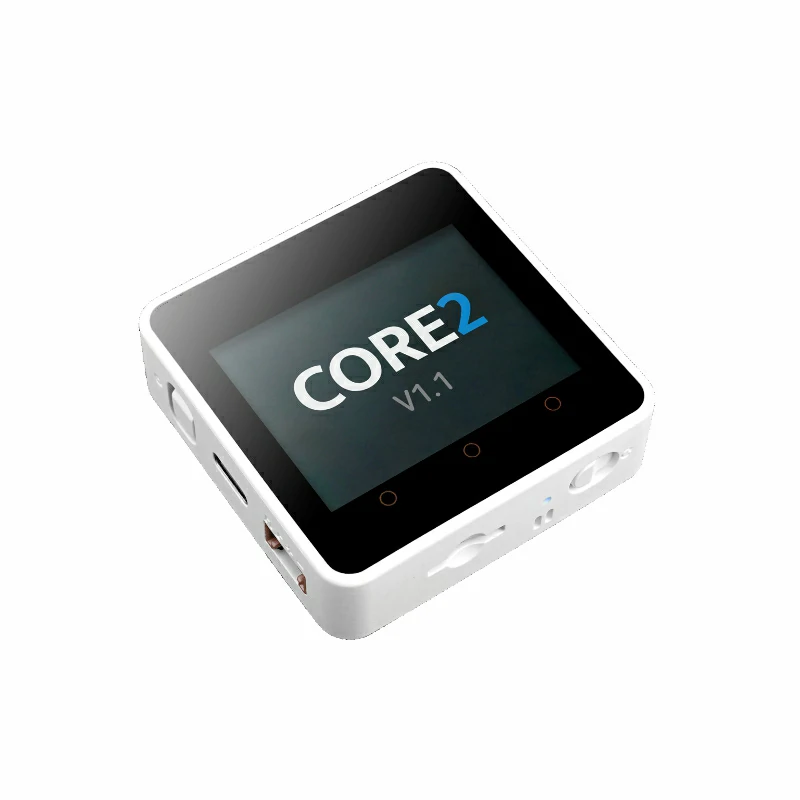
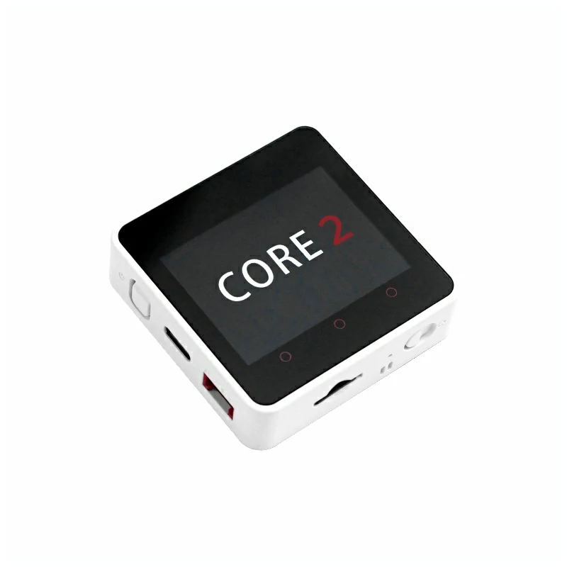
Core2 v1.3 is a highly integrated controller designed for IoT applications. It features the ESP32-D0WDQ6-V3 core with an Xtensa dual-core 32-bit LX6 processor running at 240 MHz. The board includes 16MB of Flash, 8MB of PSRAM, and supports 2.4 GHz Wi-Fi. This version is an iteration of Core2 v1.0, retaining the AXP192 power management IC while upgrading the 6-axis IMU on the rear expansion board to a BMI270, which improves pose detection accuracy and overall performance without compromising system architecture or compatibility. For human-machine interaction, the device features a 2.0" color capacitive touchscreen. The three dot-shaped touch zones on the front panel are programmable and can be mapped to three virtual buttons. A built-in vibration motor provides tactile feedback. For storage and audio, the board includes a microSD card slot and a speaker, with audio output delivered via an I2S digital interface through the NS4168 amplifier to minimize distortion and enhance sound quality. The device also integrates an RTC real-time clock IC and a 500mAh lithium battery. The rear expansion board incorporates a BMI270 6-axis IMU and a microphone, supporting motion sensing and audio capture. This product is well-suited for IoT terminals, human-machine interaction devices, pose detection, and embedded multi-function development applications.
This tutorial explains how to program and control the Core2 device using the Arduino IDE.
Notes
The built-in vibration motor of Core2 v1.3 has a structural interference with Base series bases. To prevent damage to the device, do not stack Core2 v1.3 with any Base series expansion base.
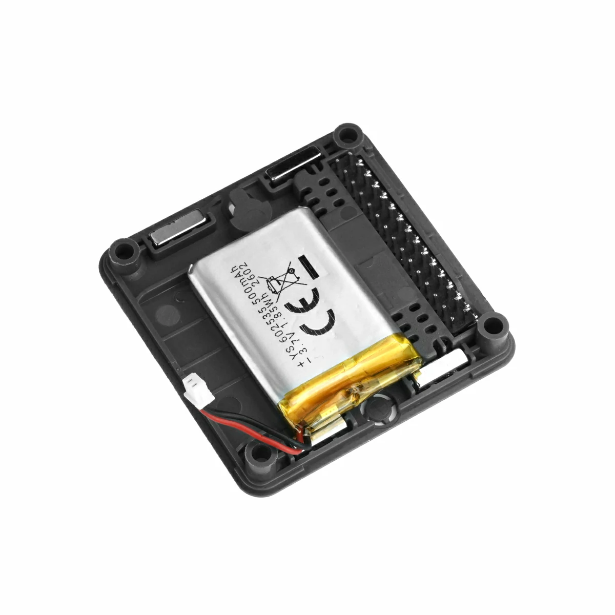
When stacking Core2 v1.3 with M5 modules, you will need to remove the battery bottom of Core2 v1.3. If you need to retain the I2S microphone, IMU, and battery functions of the base while stacking additional modules, it is recommended to use the M5GO Bottom2.
Some screen edges may exhibit touch non-linearity. You can try using M5Tool to upgrade the screen firmware to resolve this issue.
Features
ESP32-D0WDQ6-V3 Core:
16MB Flash
8MB PSRAM
2.4 GHz Wi-Fi
Human-Machine Interaction
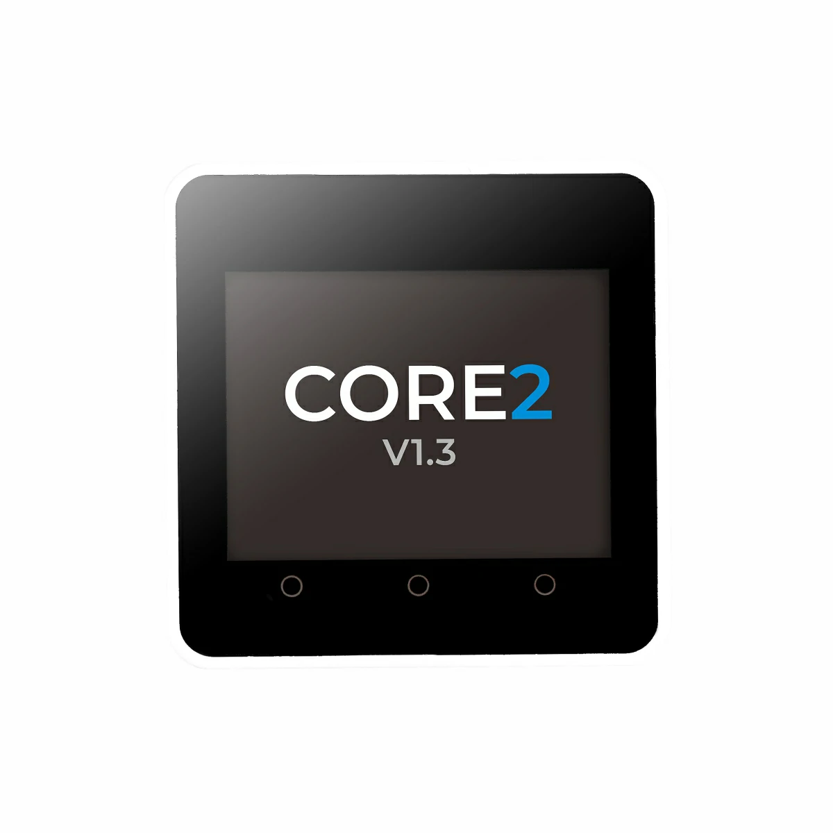
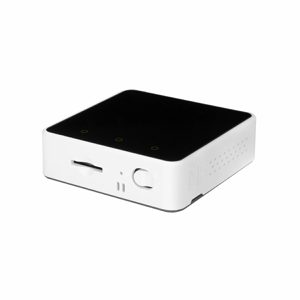
2.0" Color Capacitive Touchscreen
Built-in Speaker
Vibration Motor
Standalone Peripheral Expansion Board
BMI270 6-Axis IMU
PDM Microphone
AXP192 Power Management
RTC Clock
Built-in 500mAh Lithium Battery
HY2.0-4P Expansion Interface
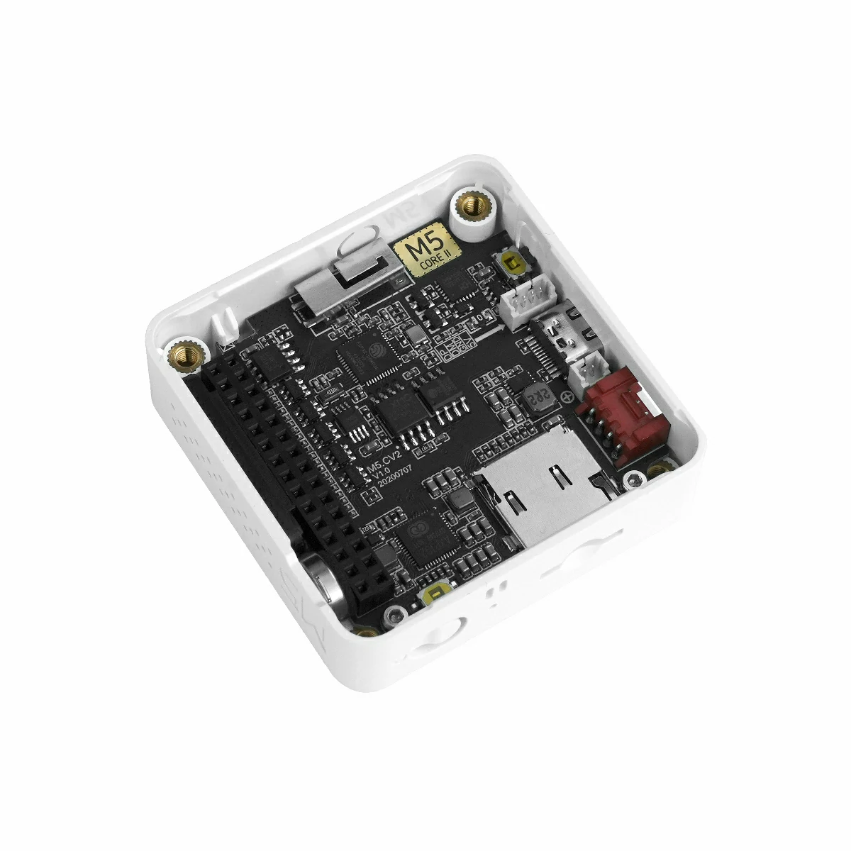
microSD Card Slot
Development Platforms
UiFlow1
UiFlow2
Arduino IDE
ESP-IDF
PlatformIO
Includes
1 x Core2 v1.3
1 x USB Type-C Cable (20cm)
1 x Hex Key L-Shape 2.0mm (For M2.5 Screw)
Applications
IoT Controller
DIY Projects
Smart Home Devices
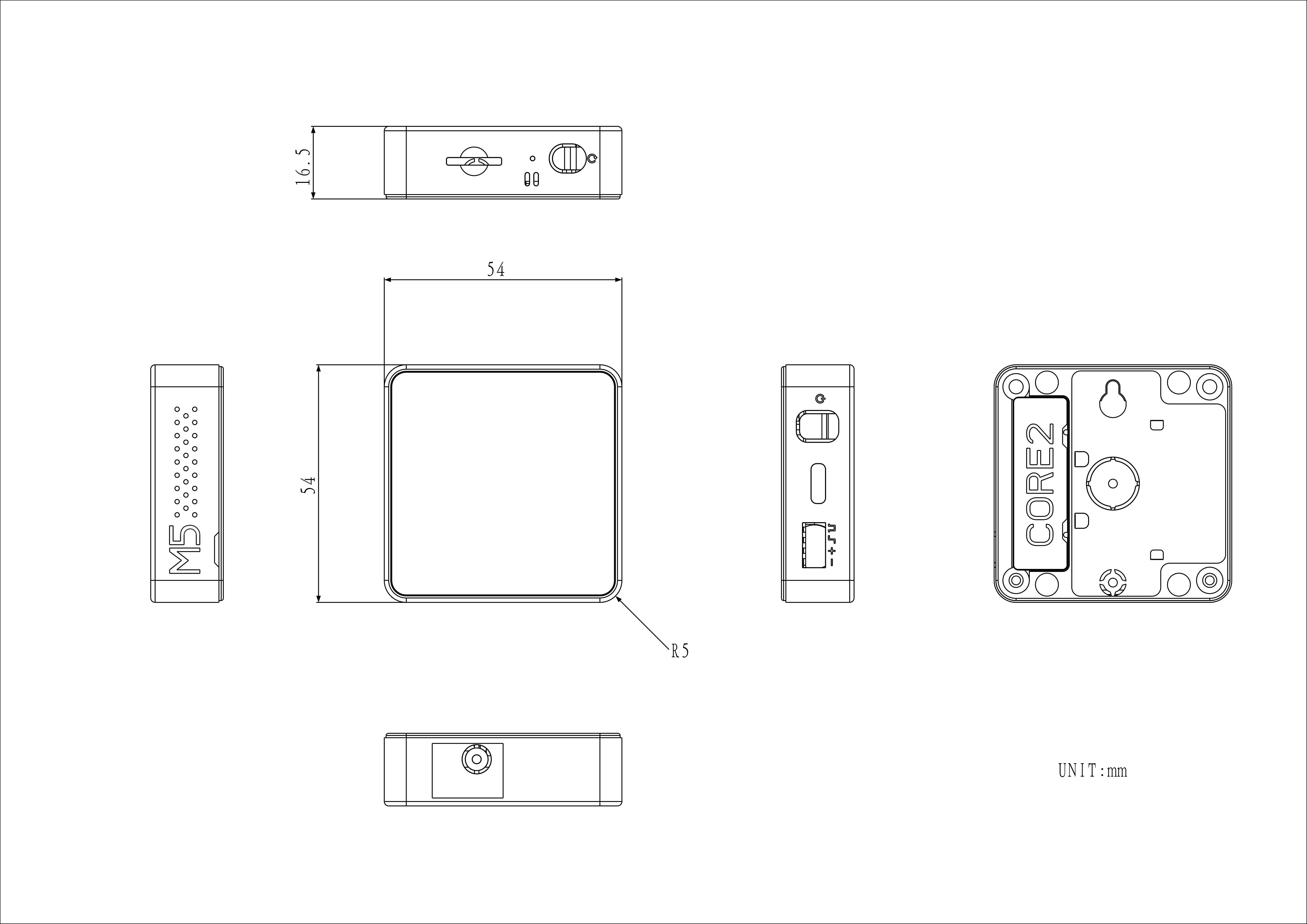
Specifications
Specification
Parameter
SoC
ESP32-D0WDQ6-V3@Dual-Core Processor, 240MHz
Flash
16MB
PSRAM
8MB
Wi-Fi
2.4 GHz Wi-Fi
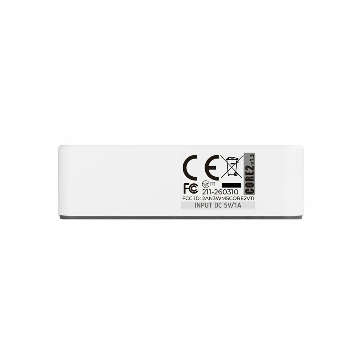
Input Voltage
5V @ 500mA
Host Interface
USB Type-C x 1, GROVE (I2C+I/O+UART) x 1
LED
Green Power Indicator
Buttons
Power Button, RST Button, Screen Virtual Buttons x 3
Download and install the CH9102 USB serial (VCP) driver from the table below according to your operating system. When installing CH9102_VCP_SER_MacOS v1.7, the installer may display an error message, which is typically a false positive — the driver is usually installed correctly and you can safely dismiss the prompt and proceed. If firmware flashing or downloading fails, times out, or returns errors such as Failed to write to target RAM, try reinstalling the driver or switching to a different USB cable or port.
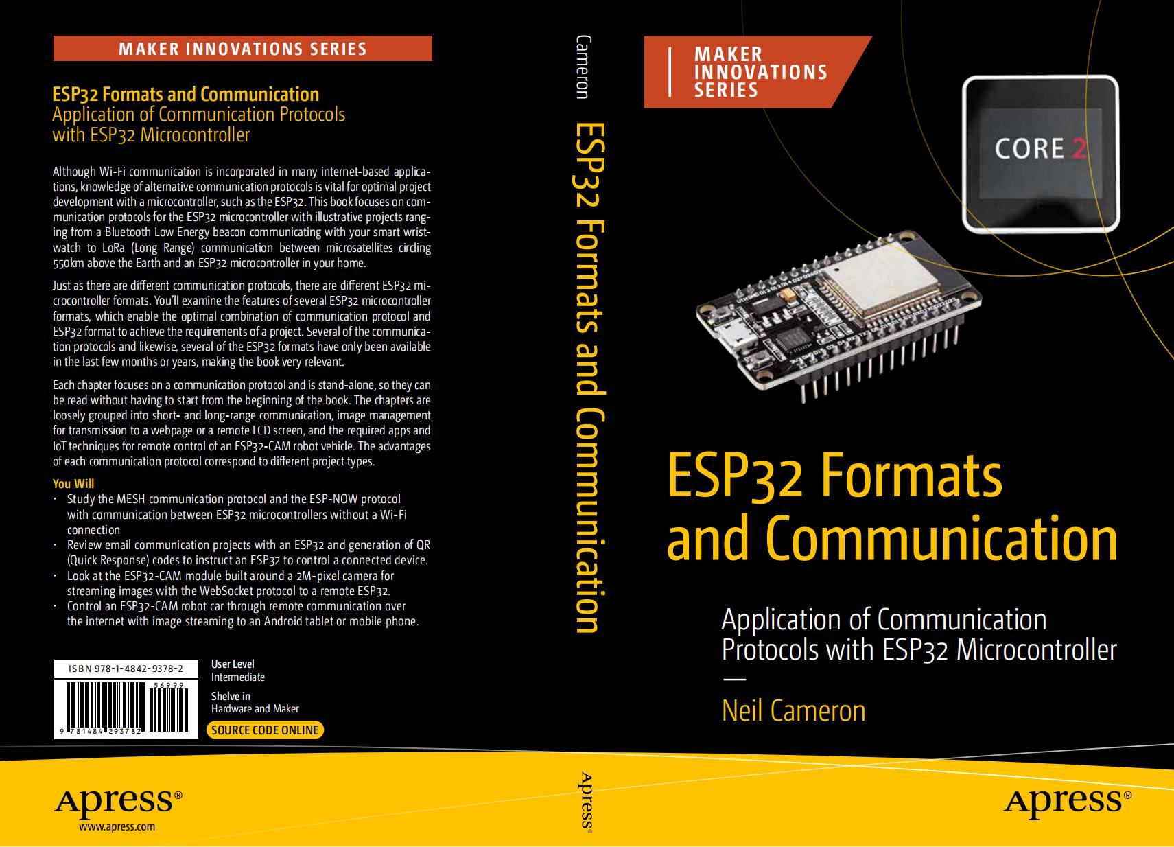
ESP32 Formats and Communication Protocols dedicates several chapters to the M5Stack Core2 module. The M5Stack Core2 integrates a touch LCD screen with Wi-Fi connectivity, a microphone and speaker, as well as an accelerometer and gyroscope, making it an exceptionally versatile platform. The book uses communication protocols to build a variety of projects — ranging from connecting a smartwatch to a smartphone (BLE) and long-range communication with satellites orbiting Earth (LoRa), to audio signal transmission between devices (I2S). It also covers the use of QR codes for controlling external devices over the internet, as well as ESP-MESH and ESP-NOW protocols for enabling communication between microcontrollers without an internet connection.
Video
Core2 v1.3 Product Introduction and Feature Demonstration
To compare products across the controller series, visit the Product Selection Table and select the target products to view a side-by-side comparison. The table covers key parameters and feature highlights, supporting simultaneous comparison of multiple products.