
Tab5
SKU:C145/K145


Description
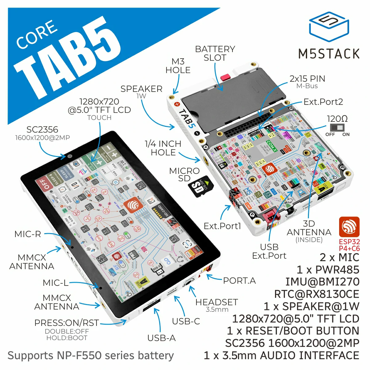
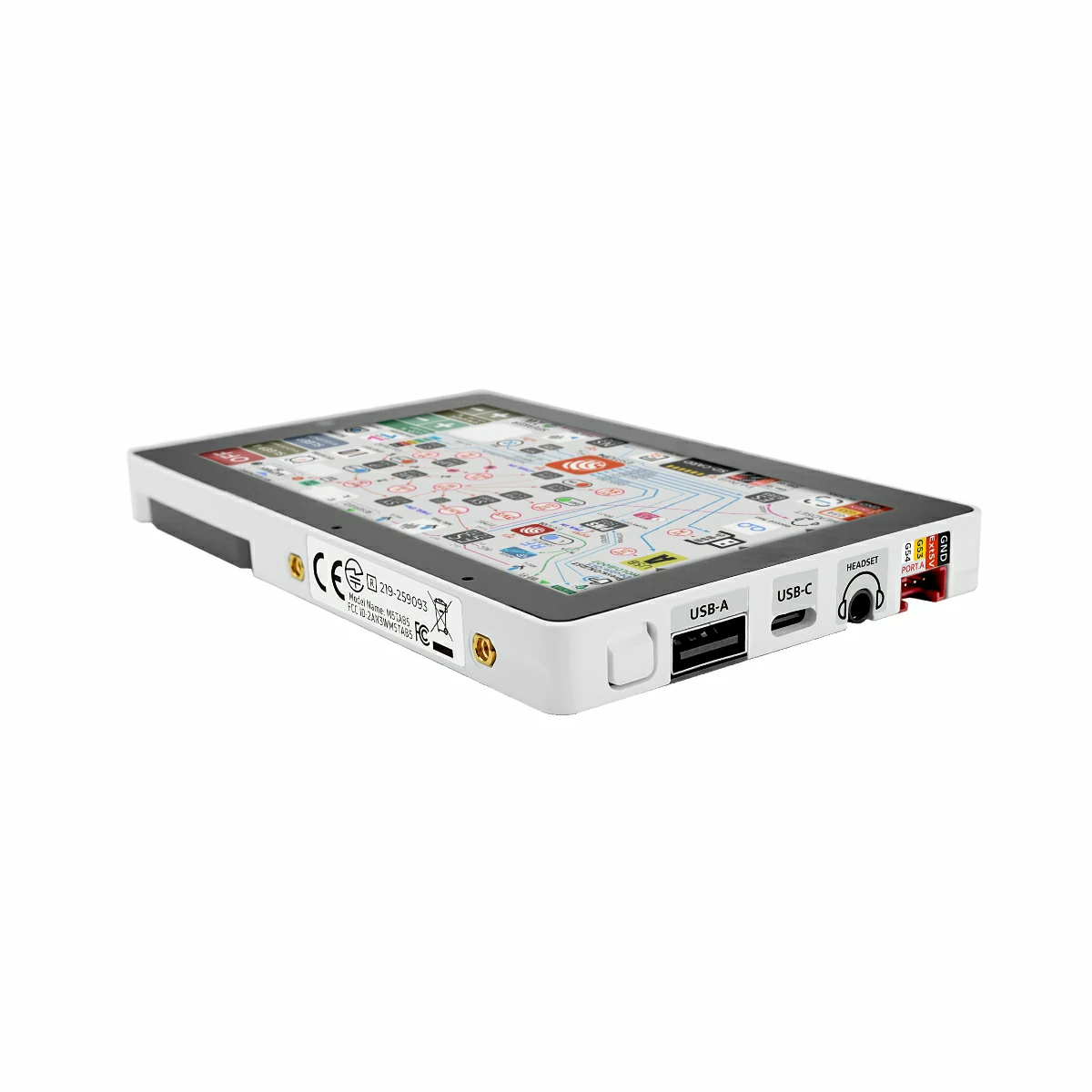
Tab5 is a highly expandable, portable smart-IoT terminal development device for developers, integrating a dual-core architecture and rich hardware resources. The main controller adopts the ESP32-P4 SoC based on the RISC-V architecture, with 16MB Flash and 32MB PSRAM. The wireless module uses the ESP32-C6-MINI-1U, supporting Wi-Fi 6. Its antenna system can freely switch between the built-in 3D antenna and an external MMCX antenna interface, flexibly adapting to various deployment environments to ensure data throughput and low-latency control.
In terms of visual and interactive experience, the Tab5 is equipped with a 5″ 1280×720 IPS touchscreen featuring an MIPI‑DSI interface, delivering a smooth and responsive touch interaction. It also comes with an SC2356 2MP camera (1600×1200) that uses an MIPI‑CSI interface, enabling HD video recording, image processing, and edge AI applications such as facial recognition and object tracking.
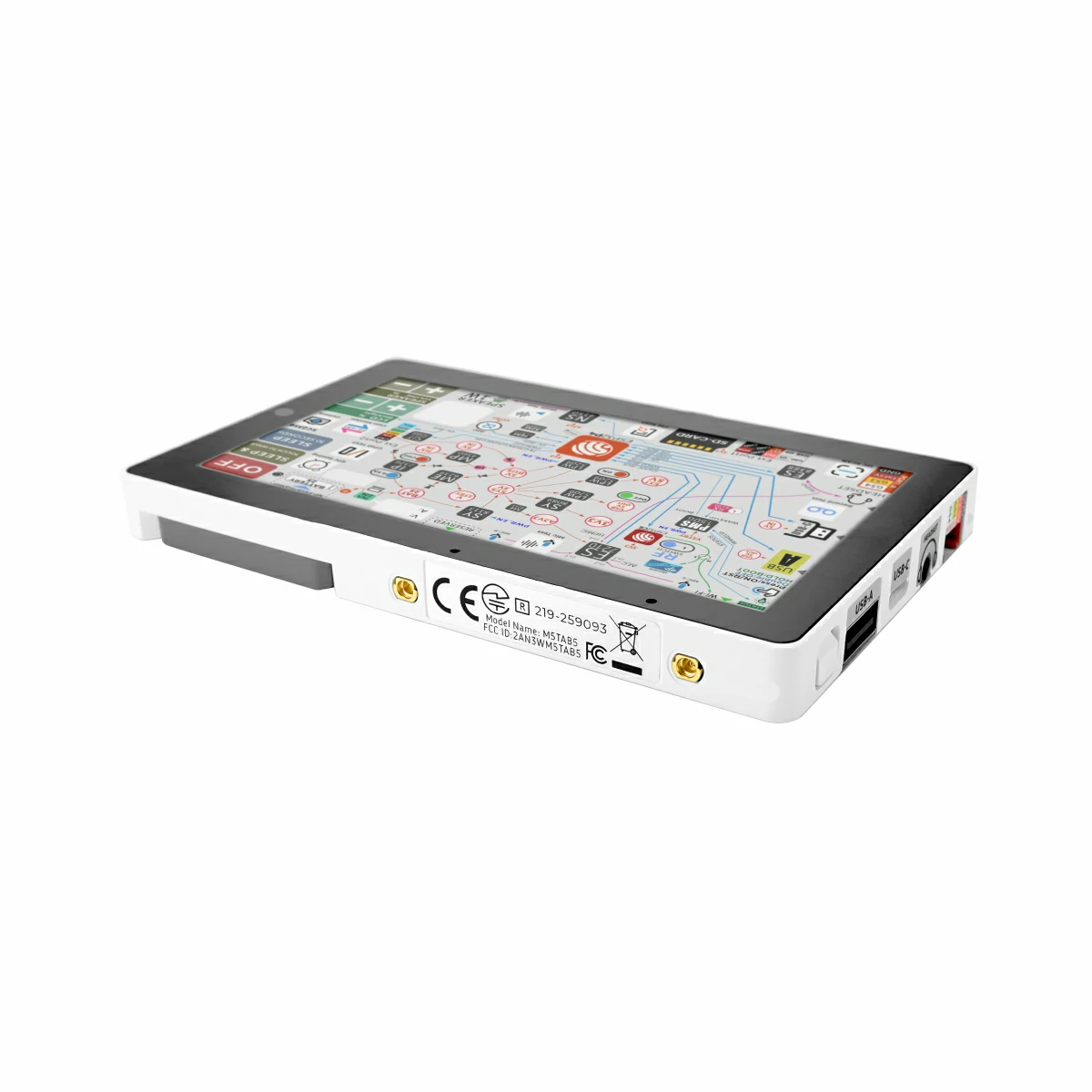
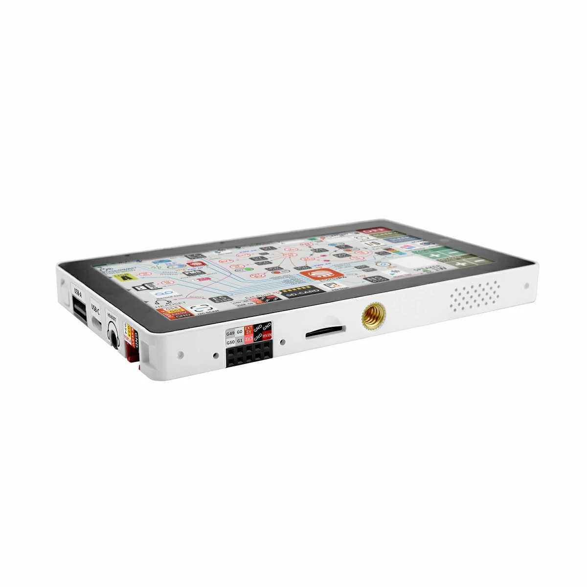
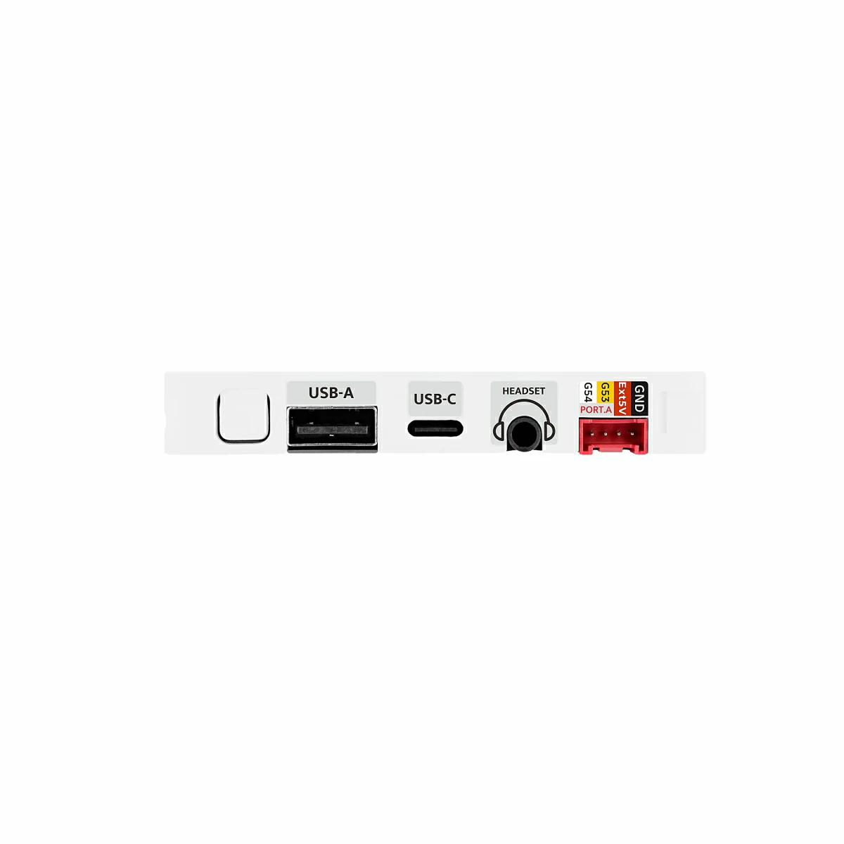
Peripheral interfaces include USB Type-A (Host) and USB Type-C (USB 2.0 OTG) for mouse, keyboard and other devices. Industrial users can leverage RS-485 (SIT3088 + switchable 120Ω terminator). HY2.0-4P, M5-Bus, GPIO_EXT headers, a microSD slot, and reserved STAMP pads (for Cat-M, NB-IoT, LoRaWAN, etc.) enable versatile sensor and communication expansion. Reset/Boot buttons provide quick reset and download-mode entry.
Audio features consist of an ES8388 codec plus an ES7210 AEC front-end, a dual-mic array, 3.5mm headphone jack and speaker, supporting Hi-Fi recording/playback and accurate voice recognition. A BMI270 6-axis sensor (accelerometer + gyroscope, interrupt wake-up) can wake the MCU in motion-tracking scenarios, boosting response efficiency in low-power mode.
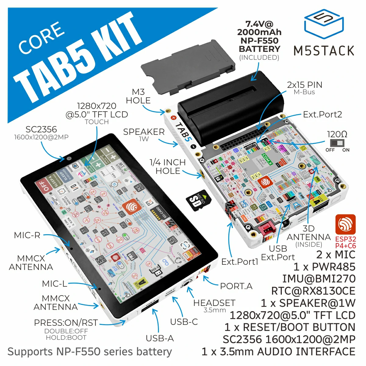
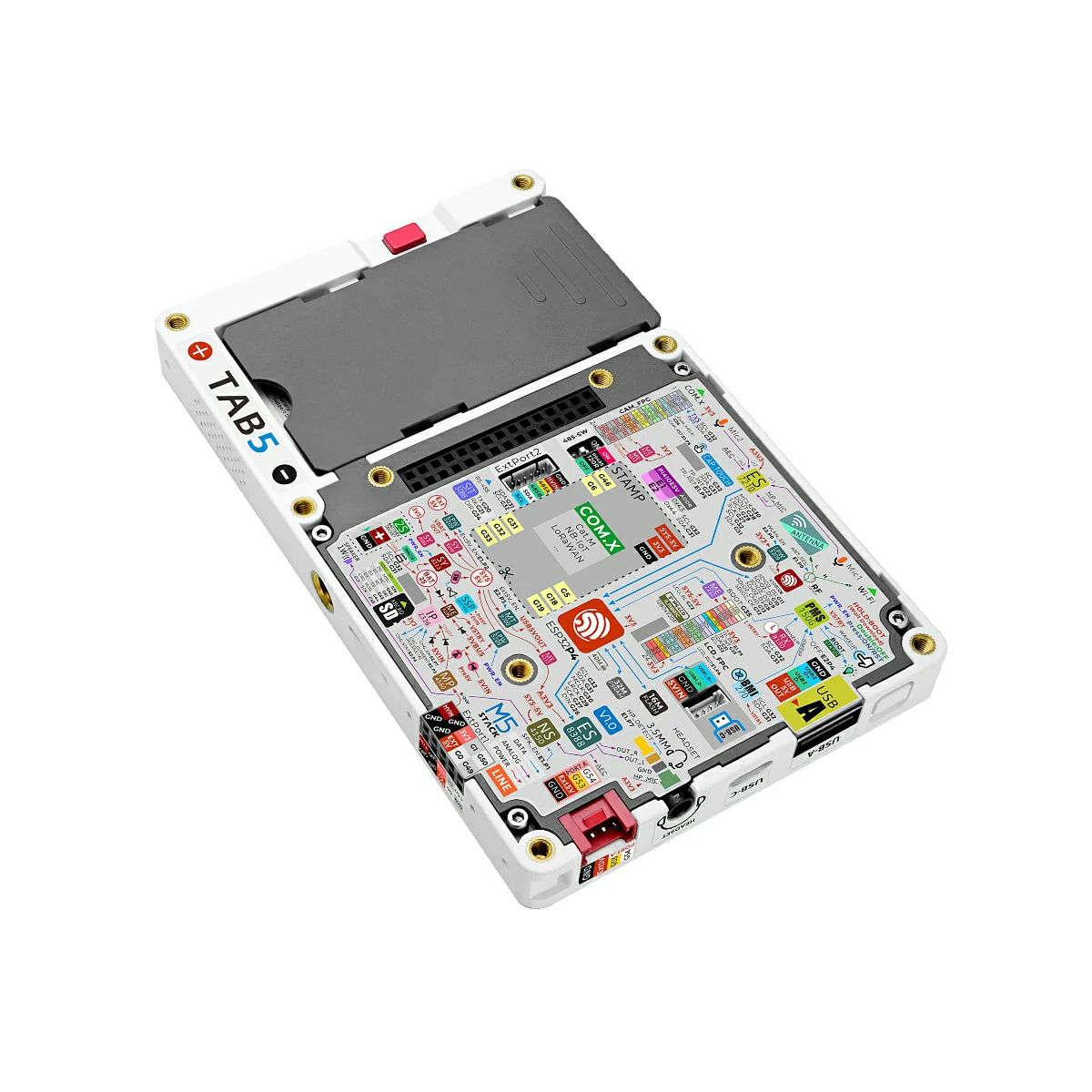
For time and power, Tab5 integrates an RX8130CE RTC (timed interrupt wake-up). The base accepts a removable NP-F550 battery and features MP4560 buck-boost, IP2326 charge management, and INA226 real-time monitoring for stable standalone operation.
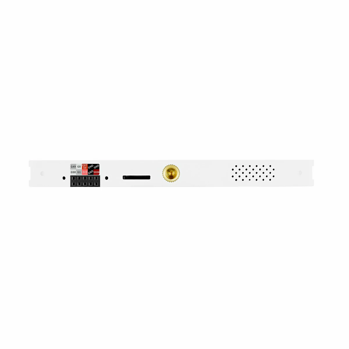
A 1/4″-20 tripod nut on the side allows direct mounting to a tripod or bracket.
Applications include smart-home control, remote monitoring, industrial automation, IoT prototyping and education, offering a full-featured, easily expandable high-performance platform.
Tutorial & Quick Start


Features
- ESP32-P4 dual-core MCU
- ESP32-C6 wireless module
- 2.4 GHz Wi‑Fi 6
- Built‑in 3D antenna & MMCX external antenna port
- 5‑inch IPS TFT display, resolution 1280×720 (720P)
- SC2356 2MP camera
- USB Type-A Host + USB Type-C OTG
- RS485 industrial interface
- HY2.0-4P & M5-Bus expansion
- microSD card slot
- Stamp expansion pads
- ES8388 audio codec
- ES7210 AEC dual microphones
- 1W speaker + 3.5mm headphone jack
- BMI270 6-axis sensor
- RX8130CE real-time clock
- Reset/Boot & Power keys
- Removable NP-F550 battery
- Standard 1/4″-20 tripod-mount nut
- Development Platform
- UiFlow2
- Arduino IDE
- ESP-IDF
- PlatformIO
Includes
Tab5 (SKU:C145)
- 1 x Tab5
- 1 x 1.25-6P Single-ended Terminal Cable
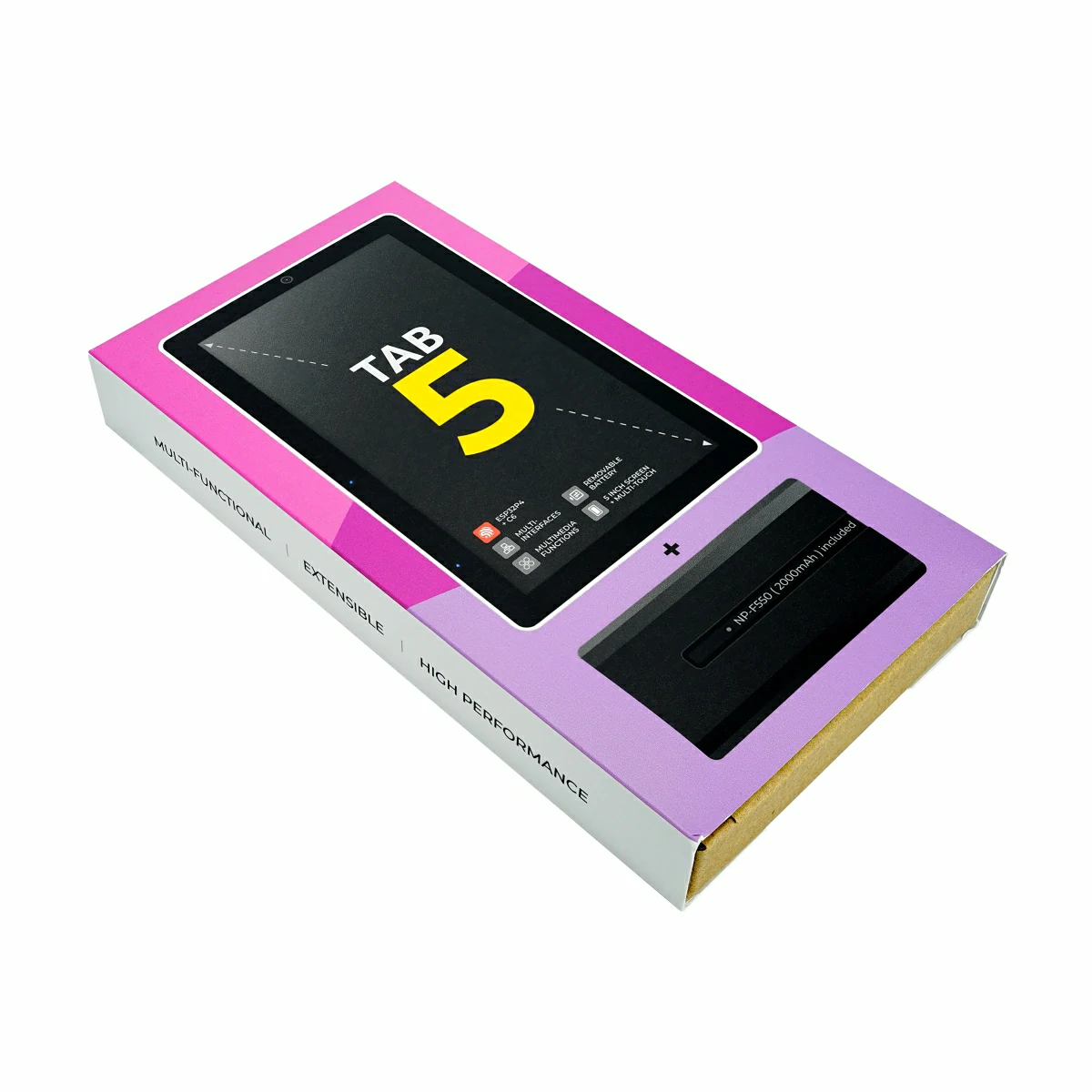
Tab5 Kit (SKU:K145)
- 1 x Tab5 Kit
- 1 x 1.25-6P Single-ended Terminal Cable
- 1 x NP-F550 2000mAh Removable Battery
Applications
- Smart-home control
- Remote monitoring systems
- IoT device development
- Industrial automation
Specifications
| Specification | Parameter |
|---|---|
| Main Controller SoC | ESP32-P4NRW32@RISC-V 32-bit Dual-core 360MHz + LP Single-core 40MHz |
| Wireless Module SoC | ESP32-C6-MINI-1U |
| Flash | 16MB |
| PSRAM | 32MB Octal |
| Wi-Fi | 2.4 GHz Wi-Fi 6, Thread, Zigbee |
| Antenna | Built-in 3D antenna & 2 x MMCX external antenna ports |
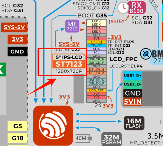
| Display | Uses a 5‑inch IPS TFT display with a resolution of 1280×720 (720P), equipped with an integrated display and touch driver IC: ST7123 / ST7121 |
| Camera | SC2356 @ 2MP (1600×1200), via MIPI‑CSI interface |
| Audio Chip | ES8388 codec, ES7210 AEC front end |
| Microphone | Dual microphone system (AEC echo cancellation) |
| Speaker | 1W@8Ω NS4150B |
| Headphone Jack | 3.5mm |
| USB Ports | USB Type-A (Host), USB Type-C (USB 2.0 OTG) |
| RS485 Port | SIT3088 (120Ω switchable terminal resistor) Power supply range: 6 ~ 24V |
| Expansion Interface | 1× HY2.0-4P, 1× M5-Bus, GPIO_EXT expansion bus |
| Storage Expansion | microSD card slot |
| Extensible Stamp Interface | Stamp pads (support Cat.M / NB‑IoT / LoRaWAN and other modules) |
| Motion Sensor | BMI270 six-axis (accelerometer + gyroscope, support interrupt wake-up) |
| RTC | RTC Chip: RX8130CE (supports timed interrupt wake-up), RTC supercapacitor specification: 70000μF/3.3V, size Φ4.8×1.4mm |
| Reset/Boot Button | 1x Button, for power on/off and entering download mode |
| Charging Management | IP2326 charging management chip |
| Real-time Power Monitoring | INA226 (bus current / voltage monitoring) |
| Battery | NP-F550 removable lithium battery, 7.4V@2000mAh (14.8 Wh) |
| Battery Life | Under standard usage environment (screen brightness 50%, Wi‑Fi always on, background tasks running), Tab5 built-in battery discharges from full (8.23 V) to shutdown threshold (6.0 V), lasting about 6 hours. |
| Operating Temperature | 0 ~ 40°C |
| Product Size | Tab5: 128.0 x 80.0 x 12.0mm Tab5 Kit: 128.0 x 80.0 x 26.7mm |
| Product Weight | Tab5: 118.4g Tab5 Kit: 217.3g Battery: 98.9g |
| Package Size | Tab5: 148.0 x 103.0 x 21.0mm Tab5 Kit: 191.0 x 103.0 x 25.0mm |
| Gross Weight | Tab5: 161.5g Tab5 Kit: 280.5g |
Learn
Tab5 Power Supply
Tab5 Charging
2.When the battery is over-discharged and its voltage drops below 6V, it enters protection mode. Before recharging, remove the battery, reset the device, reinstall it, and then charge via the device’s USB Type-C port.
During the initial charging phase, since the battery is still in protection mode, the charging chip trickle-charges with a small current. This state lasts several minutes, depending on the battery voltage level. Once the voltage rises above 6V, the chip automatically switches to normal charging mode.
Power On/Off
Download Mode
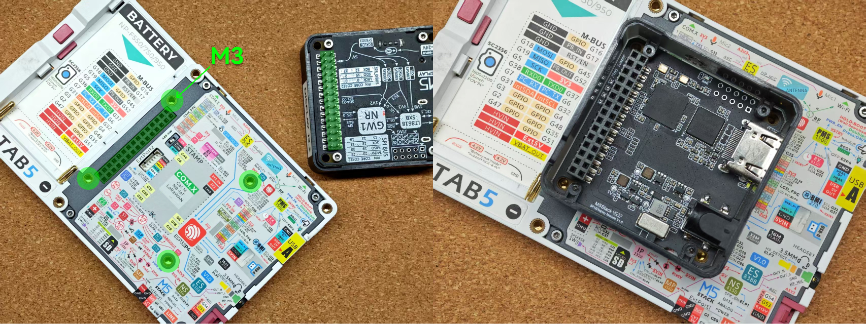
Battery Installation Notes
M5-Bus Expansion
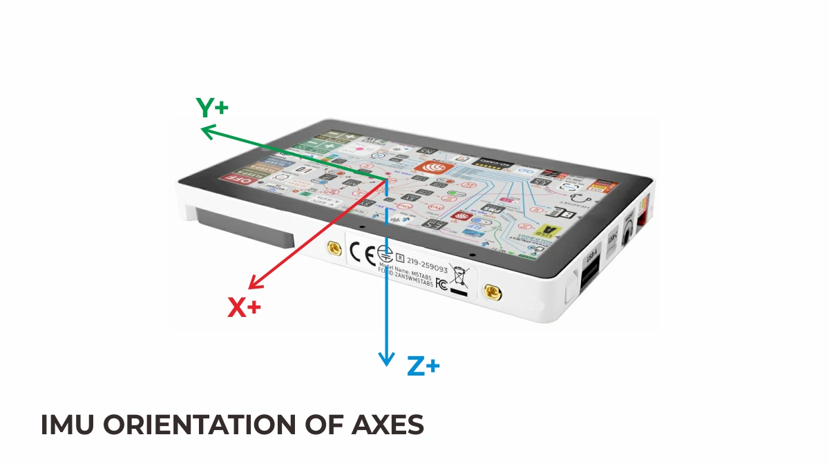
IMU Triaxial Direction Schematic Diagram
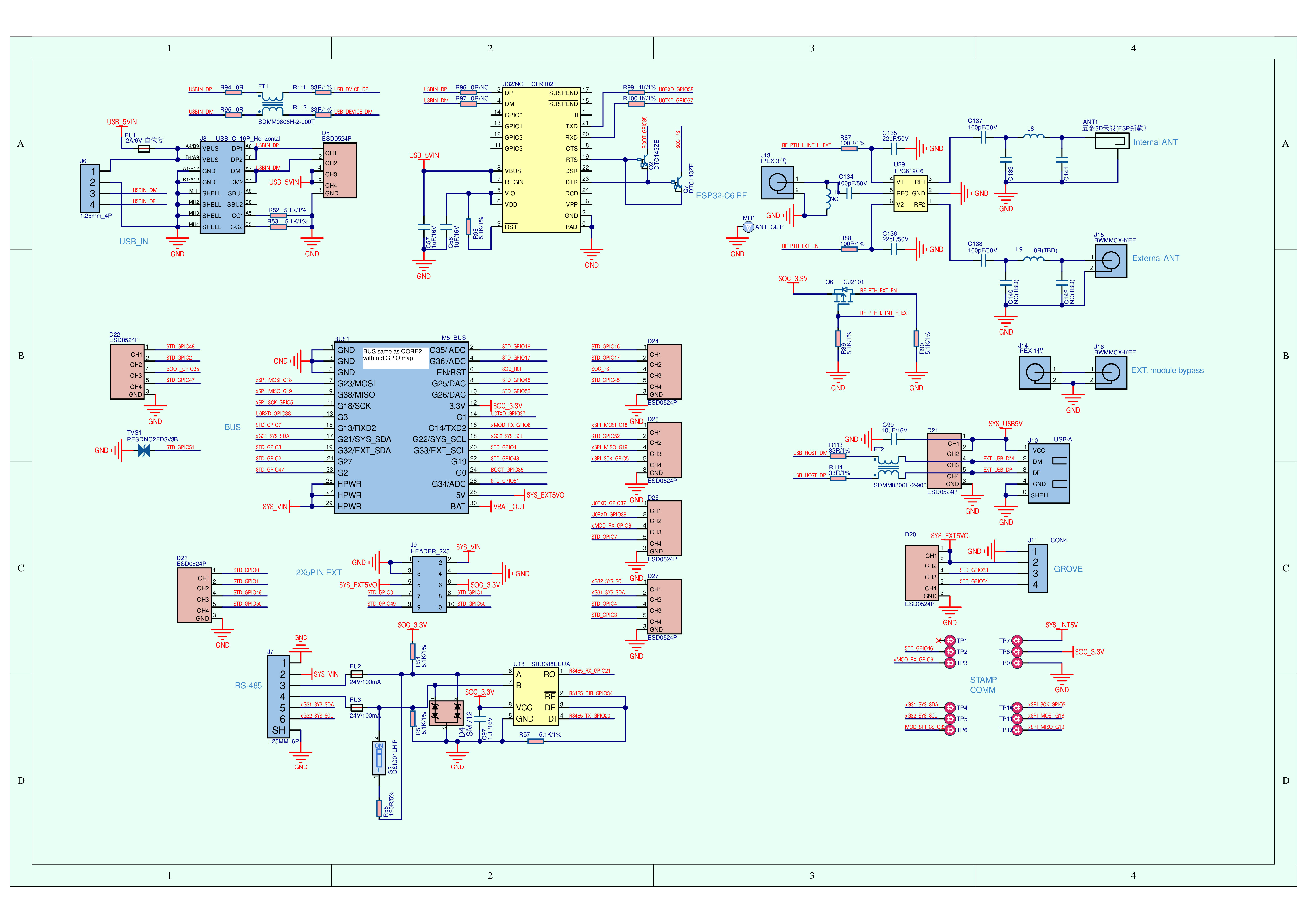
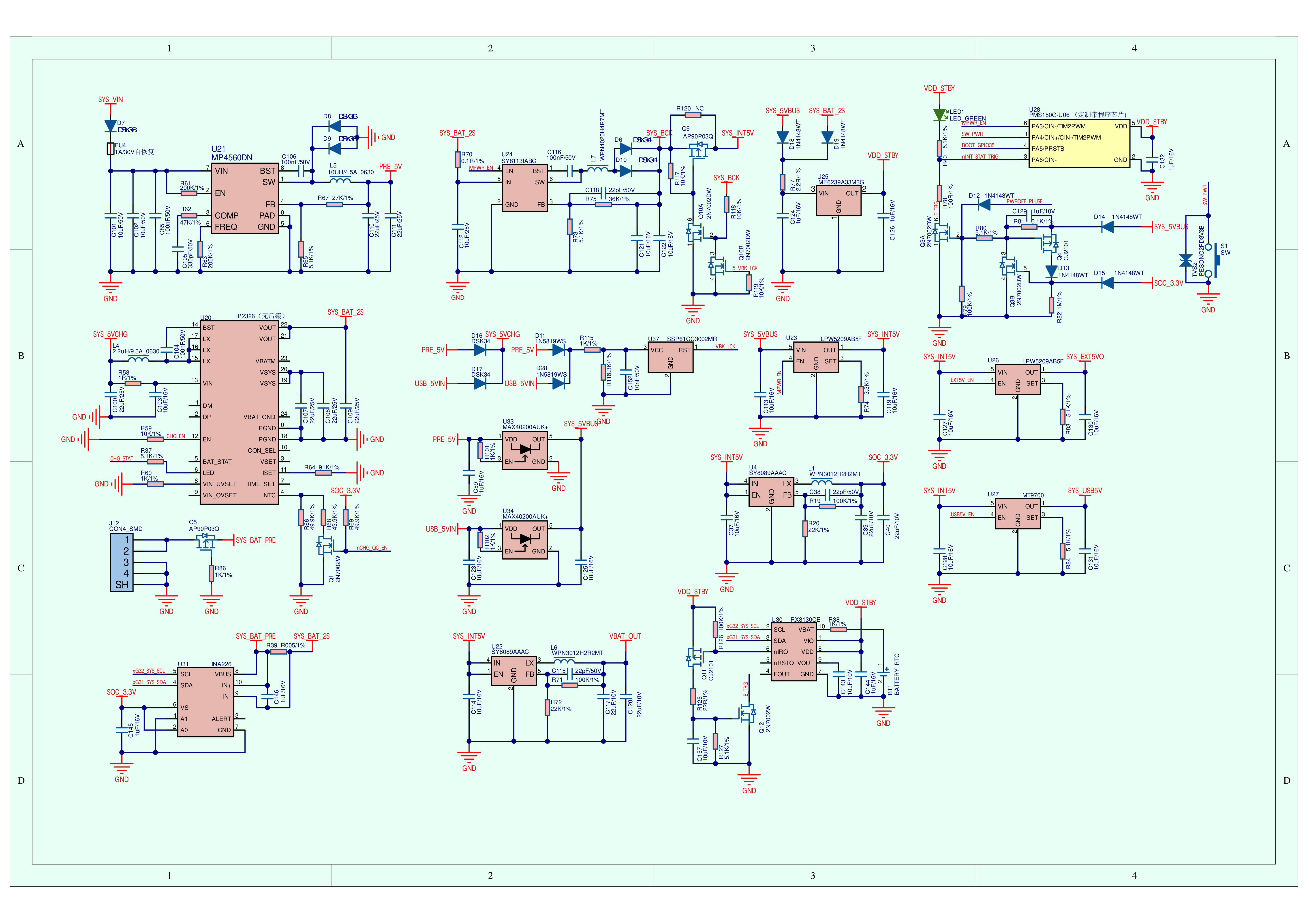
Schematics
PinMap
CAM
| ESP32‑P4 | CAM |
|---|---|
| G32 | CAM_SCL |
| G31 | CAM_SDA |
| G36 | CAM_MCLK |
| CSI_DATAP1 (Dedicated) | CAM_D1P |
| CSI_DATAN1 (Dedicated) | CAM_D1N |
| CSI_CLKP (Dedicated) | CAM_CSI_CKP |
| CSI_CLKN (Dedicated) | CAM_CSI_CKN |
| CSI_DATAP0 (Dedicated) | CSI_DOP |
| CSI_DATAN0 (Dedicated) | CSI_DON |
ES8388
| ESP32-P4 | G30 | G27 | G26 | G29 | G32 | G31 |
|---|---|---|---|---|---|---|
| ES8388 (0x10) | MCLK | SCLK | DSDIN | LRCK | SCL | SDA |
ES7210
| ESP32-P4 | G30 | G27 | G28 | G29 | G32 | G31 |
|---|---|---|---|---|---|---|
| ES7210 (0x40) | MCLK | SCLK | ASDOUT | LRCK | SCL | SDA |
LCD
| ESP32‑P4 | ILI9881C / ST7123 / ST7121 |
|---|---|
| G22 | LEDA |
| DSI_CLKN (Dedicated) | DSI_CK_N |
| DSI_CLKP (Dedicated) | DSI_CK_P |
| DSI_DATAN1 (Dedicated) | DSI_D1_N |
| DSI_DATAP1 (Dedicated) | DSI_D1_P |
| DSI_DATAN0 (Dedicated) | DSI_D0_N |
| DSI_DATAP0 (Dedicated) | DSI_D0_P |
Touch
| ESP32‑P4 | G31 | G32 | G23 |
|---|---|---|---|
| GT911 (0x14) / ST7123 (0x55) / ST7121 (0x55) | SDA | SCL | TP_INT |
BMI270 & RTC(RX8130CE) & INA226
| ESP32-P4 | G32 | G31 |
|---|---|---|
| BMI270 (0x68) | SCL | SDA |
| RX8130CE (0x32) | SCL | SDA |
| INA226 (0x41) | SCL | SDA |
- Interrupt Wakeup (PMS150G-U06)
| PMS150G-U06 | PA6/CIN- |
|---|---|
| BMI270 (0x68) | INT(E_TRG) |
| RX8130CE | INT(E_TRG) |
ESP32-C6
| ESP32-P4 | G11 | G10 | G9 | G8 | G13 | G12 | G15 | G14 |
|---|---|---|---|---|---|---|---|---|
| ESP32-C6 | SDIO2_D0 | SDIO2_D1 | SDIO2_D2 | SDIO2_D3 | SDIO2_CMD | SDIO2_CK | RESET | IO2 |
microSD
| ESP32-P4 | G39 | G40 | G41 | G42 | G43 | G44 |
|---|---|---|---|---|---|---|
| microSD SPI Mode | MISO | CS | SCK | MOSI | ||
| microSD SDIO Mode | DAT0 | DAT1 | DAT2 | DAT3 | CLK | CMD |
RS485
| ESP32-P4 | G21 | G20 | G34 |
|---|---|---|---|
| SIT3088 | RX | TX | DIR |
HY2.0-4P
| HY2.0-4P | Black | Red | Yellow | White |
|---|---|---|---|---|
| PORT.A | GND | 5V | G53 | G54 |
PI4IOE5V6408
| ESP32-P4 | G32 | G31 | CHIP_PU |
|---|---|---|---|
| PI4IOE5V6408-1 (0x43) | SCL | SDA | RST |
| PI4IOE5V6408-2 (0x44) | SCL | SDA | RST |
| PI4IOE5V6408-1 (0x43) | E1.P0 | E1.P1 | E1.P2 | E1.P4 | E1.P5 | E1.P6 | E1.P7 |
|---|---|---|---|---|---|---|---|
| RF_PTH_L_INT_H_EXT | RF_INT_EXT_SWITCH | ||||||
| NS4150B | SPK_EN | ||||||
| EXT_5V_BUS | EXT5V_EN | ||||||
| LCD | LCD_RST | ||||||
| TP | TP_RST | ||||||
| CAM | CAM_RST | ||||||
| HEADPHONE | HP_DET |
- RF_PTH_L_INT_H_EXT: Used to switch between the internal Wi-Fi antenna and the external SMA antenna. Low level selects the internal antenna, while high level selects the external antenna.
- EXT_5V_BUS: Provides 5V power to the Tab5 rear M5-Bus, the side 2.54-10P expansion port, and the HY2.0-4P interface. The power output can be controlled via EXT5V_EN.
| PI4IOE5V6408-2 (0x44) | E2.P0 | E2.P3 | E2.P4 | E2.P5 | E2.P6 | E2.P7 |
|---|---|---|---|---|---|---|
| ESP32-C6 | WLAN_PWR_EN | |||||
| USB-A | USB5V_EN | |||||
| DEVICE PWR | PWROFF_PLUSE | |||||
| IP2326 (CHARGE IC) | nCHG_QC_EN | CHG_STAT_LED | CHG_EN |
- WLAN_PWR_EN: Enables power supply for the internal ESP32-C6 (Wi-Fi SoC).
M5-Bus
| FUNC | PIN | LEFT | RIGHT | PIN | FUNC |
|---|---|---|---|---|---|
| GND | 1 | 2 | G16 | GPIO | |
| GND | 3 | 4 | G17 | PB_IN | |
| GND | 5 | 6 | RST | EN | |
| MOSI | G18 | 7 | 8 | G45 | GPIO |
| MISO | G19 | 9 | 10 | G52 | PB_OUT |
| SCK | G5 | 11 | 12 | 3V3 | |
| RXD0 | G38 | 13 | 14 | G37 | TXD0 |
| PC_RX | G7 | 15 | 16 | G6 | PC_TX |
| Int SDA | G31 | 17 | 18 | G32 | Int SCL |
| GPIO | G3 | 19 | 20 | G4 | GPIO |
| GPIO | G2 | 21 | 22 | G48 | GPIO |
| GPIO | G47 | 23 | 24 | G35 | GPIO |
| HVIN | 25 | 26 | G51 | GPIO | |
| HVIN | 27 | 28 | 5V | ||
| HVIN | 29 | 30 | BAT |
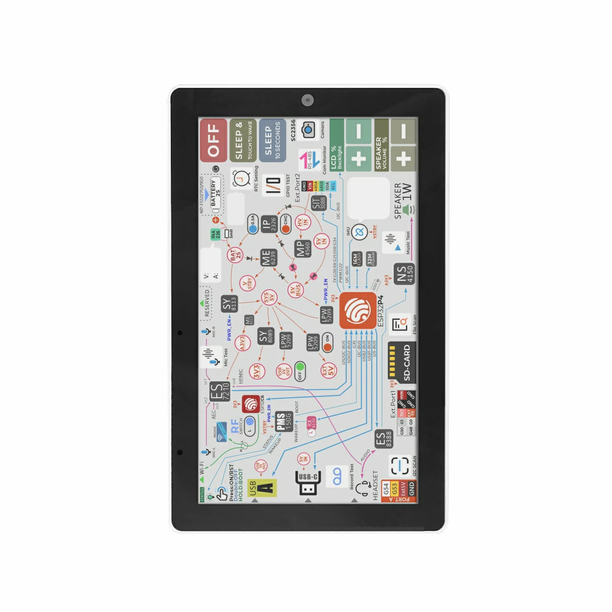
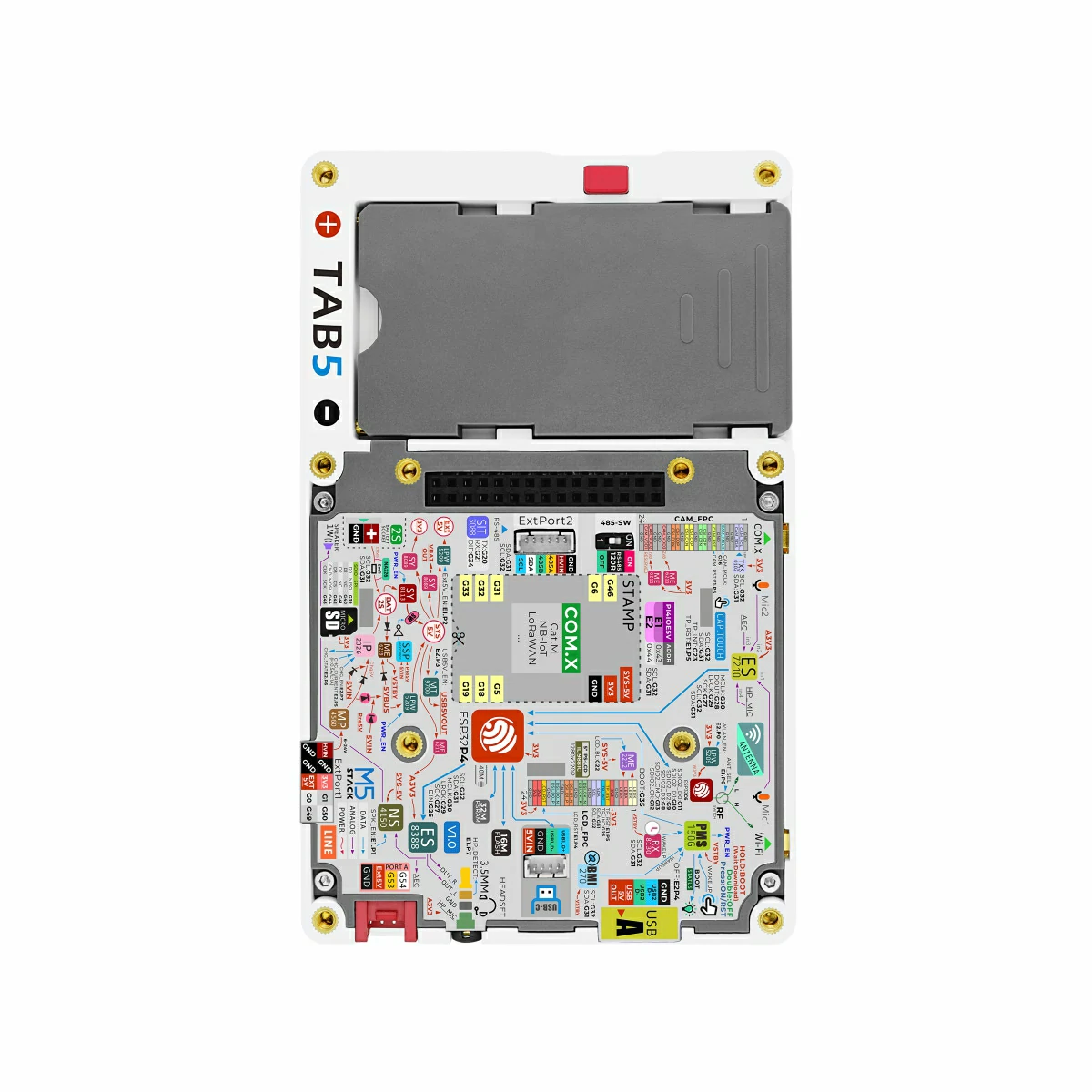
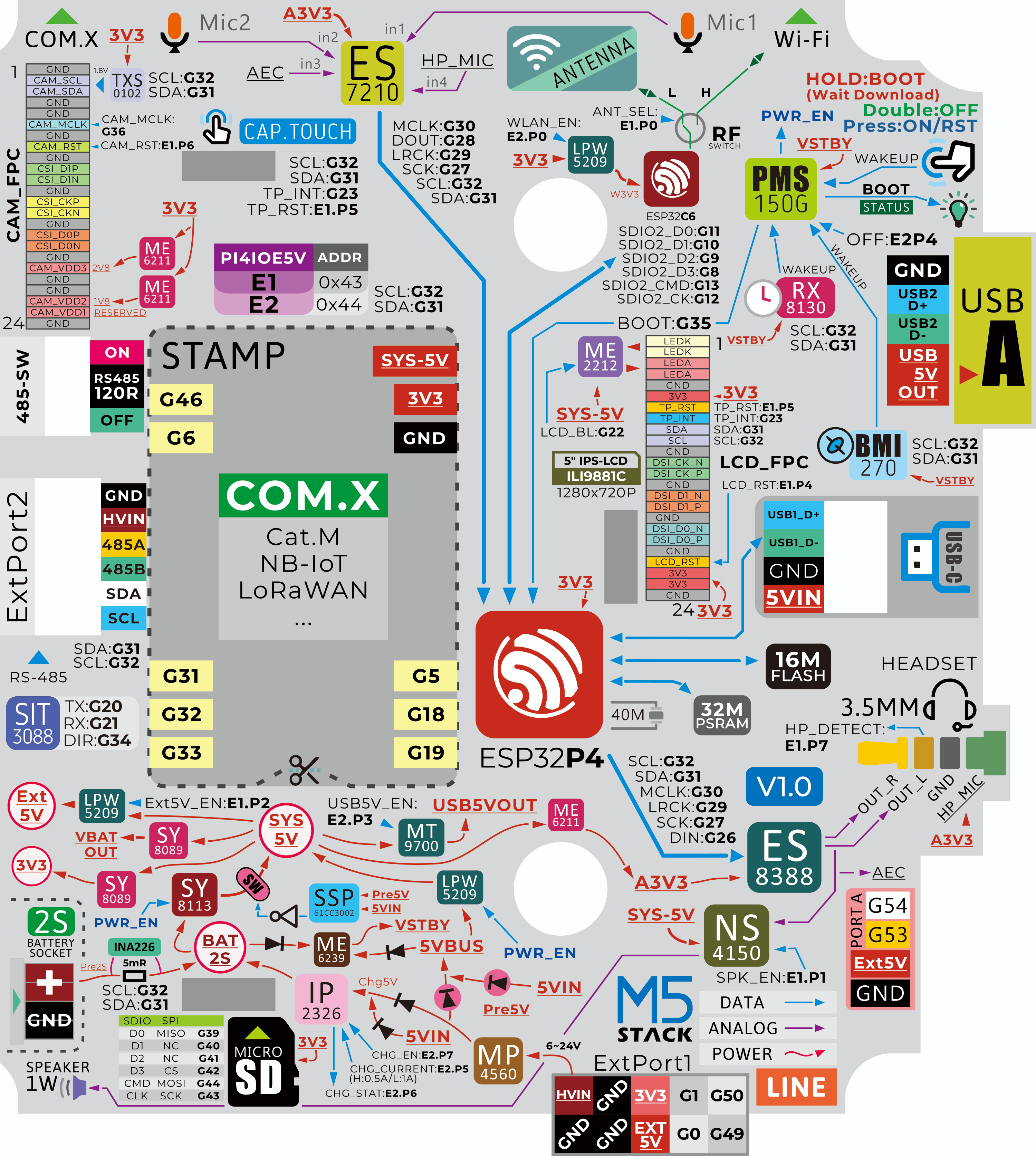
Tab5 Board PinMap Overview
Model Size
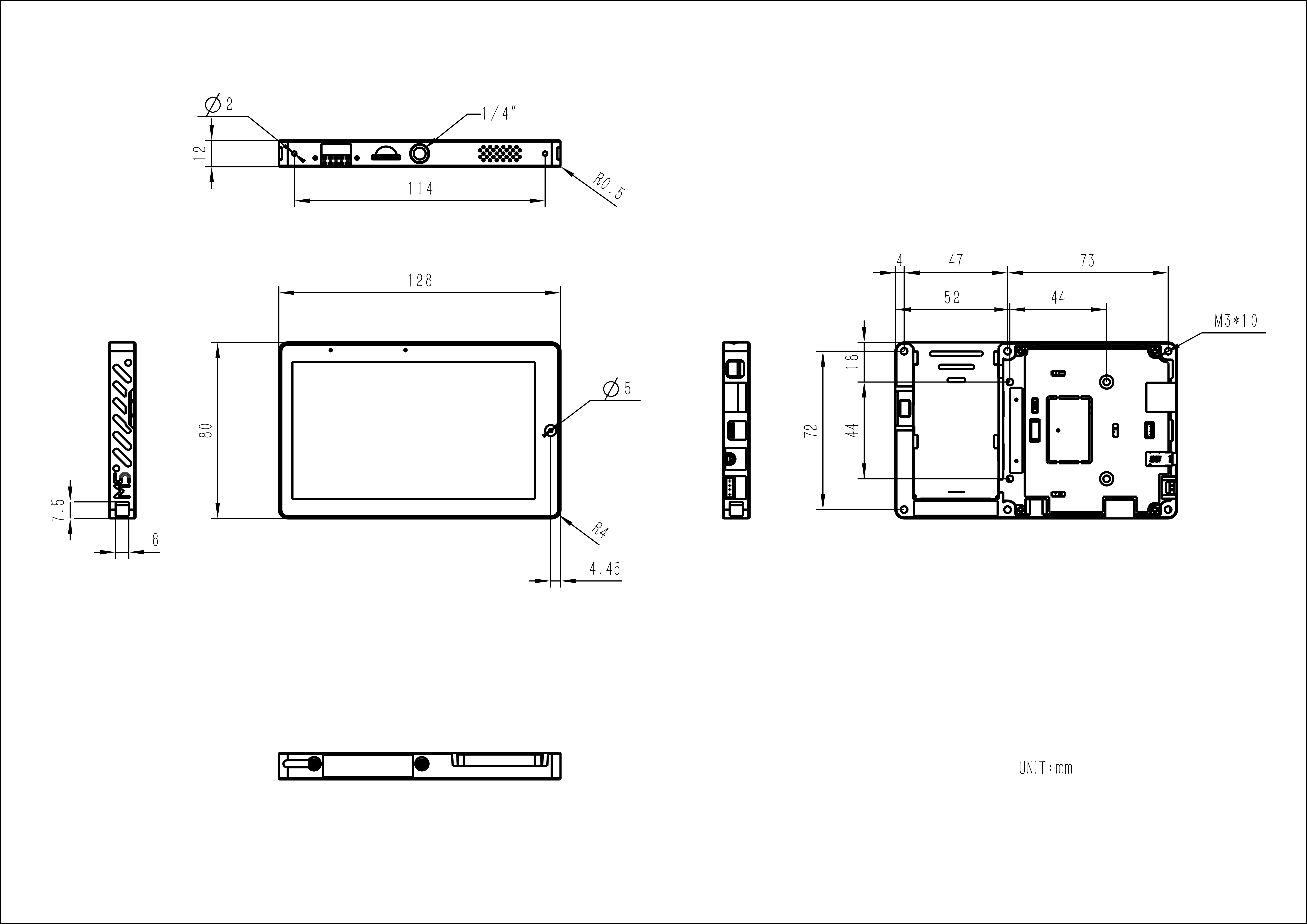
Structure
Datasheets
- ESP32-P4
- BMI270
- ESP32-C6
- NS4150B
- ES7210
- ES8388
- INA226
- IP2326
- NP-F550 Battery Report
- ST7123 Model Touch IC Interface Protocol Document
- ST7123 Model Screen Manual
- RX8130CE Datasheet
- RX8130CE Register Manual
Softwares
Arduino
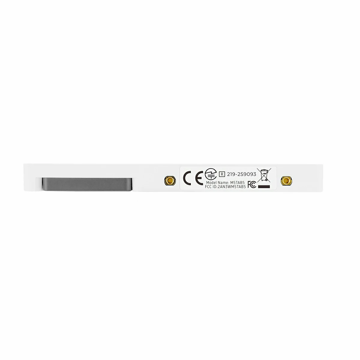
By checking the sticker on the back of the Tab5 product, you can confirm the driver model of the device.
UiFlow2
PlatformIO
[env:esp32p4_pioarduino]
platform = https://github.com/pioarduino/platform-espressif32.git#54.03.21
upload_speed = 1500000
monitor_speed = 115200
build_type = debug
framework = arduino
board = esp32-p4-evboard
board_build.mcu = esp32p4
board_build.flash_mode = qio
build_flags =
    -DBOARD_HAS_PSRAM
    -DCORE_DEBUG_LEVEL=5
    -DARDUINO_USB_CDC_ON_BOOT=1
    -DARDUINO_USB_MODE=1
lib_deps =
    https://github.com/M5Stack/M5Unified.git
https://github.com/M5Stack/M5GFX.gitESP-IDF
Easyloader
| Easyloader | Download | Note |
|---|---|---|
| Tab5 User Demo | download | / |
Others
Video
- Tab5 product introduction & demo
Version Change
| Release Date | Product Changes |
|---|---|
| 2026.4.28 | Screen driver IC model changed from ST7123 to ST7121 |
| 2025.10.14 | Tab5 screen driver solution optimized: the original independent ILI9881C display driver and GT911 touch driver were changed to an ST7123 integrated display-touch driver. |
| 2025.5.9 | Initial product release |