StickC is a compact and delicate development board. As an upgraded version of Stick, it features more expansion interfaces and buttons. It not only offers outstanding performance but also boasts low-power consumption. Whether for programming learning or project development, StickC can provide reliable hardware support. What can it do? This tiny yet exquisite development tool can fully unleash endless creative potential. StickC helps you quickly build IoT product prototypes and greatly simplifies the entire development process. Even beginners who are new to programming can use it to create interesting applications and apply them to real life. StickC is one of the core devices in the M5Stack product line, which is built upon a continuously evolving hardware and software ecosystem. It comes with numerous compatible expansion modules, abundant open-source code, and an active forum community, all of which offer users comprehensive and high-quality support throughout the development process.
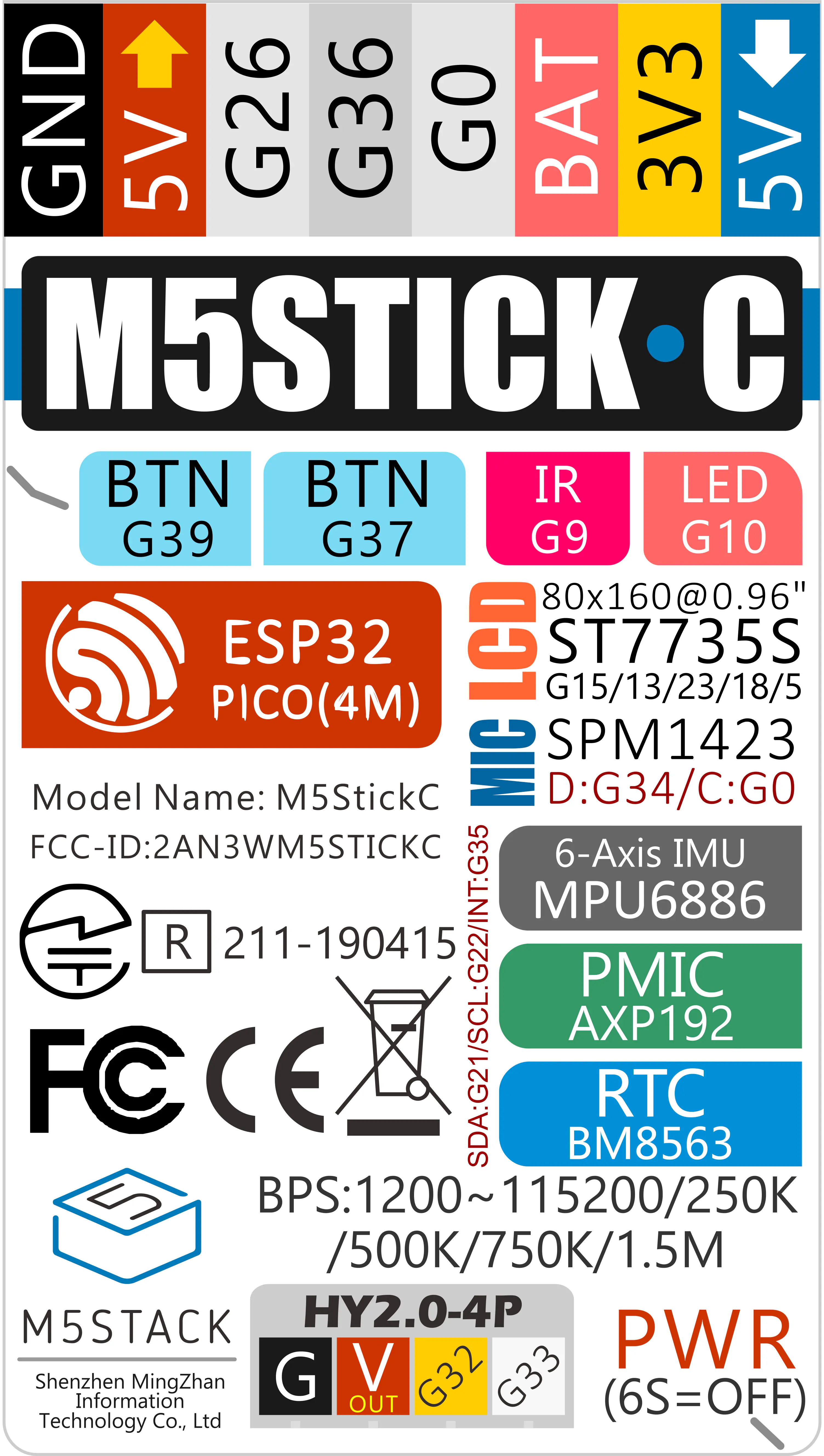
When downloading firmware, it is recommended to use the following UART baud rates. Using other speeds may cause download failure: 1500000 bps / 750000 bps / 500000 bps / 250000 bps / 115200 bps
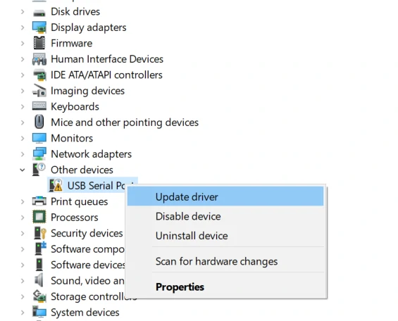
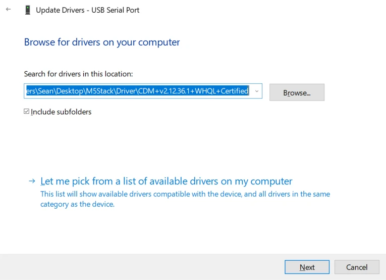
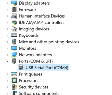
Connect the device to a PC and install the FTDI driver via Device Manager. Using Windows 10 as an example, download the driver package matching your OS, extract it, and install it through Device Manager. (Note: On certain systems, the driver may need to be installed twice to take effect. Unrecognized devices usually appear as M5Stack or USB Serial. It is recommended to install the driver directly via Device Manager using the driver files—executable installers may not work properly.) Click here to download the FTDI driver
Accelerometer, microphone, LED, IR, RTC, wireless connection and other hardware tests; press Button A or Button B to switch test items.
Video list4
Product Comparison
To compare information on the Stick series products, you can visit the Product Selection Table, check the target products, and get the comparison results. The selection table covers key information such as core parameters and functional features, and supports comparison of multiple products simultaneously.