
SwitchC6
SKU:K140


Description
SwitchC6 is an IoT single-live wire switch controller. It integrates the ESP32-C6-MINI-1 core controller and a magnetic latching relay, supports connecting to electrical load circuits of AC 100 ~ 230V, and helps quickly build IoT smart homes. The controller comes pre-installed with ESP-NOW control firmware, and provides related control protocols and SDKs, allowing users to wirelessly control it with any ESP32 device. The back adopts a rail clip design, making it easy to install on DIN rails, suitable for embedded smart home control, upgrading single-live wire lighting circuits, and other application scenarios.
Tutorial
Features
- Single-live wire switch controller
- Based on ESP32-C6-MINI-1 wireless SoC
- Suitable for tungsten filament bulbs and lamps with SCR dimming support
- 2.4 GHz Wi-Fi 6
- Integrated magnetic latching relay
- Wide voltage design: compatible with AC 100 ~ 230V electrical loads
- ESP-NOW wireless communication protocol
- Status indicator light
- DIN rail mounting
Includes
- 1 x SwitchC6
Applications
- Smart home control
- Single-live wire lighting renovation
Specifications
| Specification | Parameter |
|---|---|
| SoC | ESP32-C6-MINI-1, RISC-V 32-bit single-core processor, supports up to 160 MHz clock frequency |
| Wi-Fi | 2.4 GHz Wi-Fi 6 |
| Wireless Standard | IEEE 802.11 b/g/n/ax |
| Max Load | AC 220V@10A (2200W) / AC 110V@10A (1100W), max current limit 10A |
| Supported Voltage | AC 100 ~ 230V, 50/60Hz |
| Power Supply | Live wire only |
| Terminal Wiring Spec | Solid wire: 0.5m㎡ ~ 4m㎡ Stranded wire: 0.5mm² ~ 2.5mm² |
| Power-on State | Power-off state memory |
| Operating Temp | -10℃ ~ 60℃ |
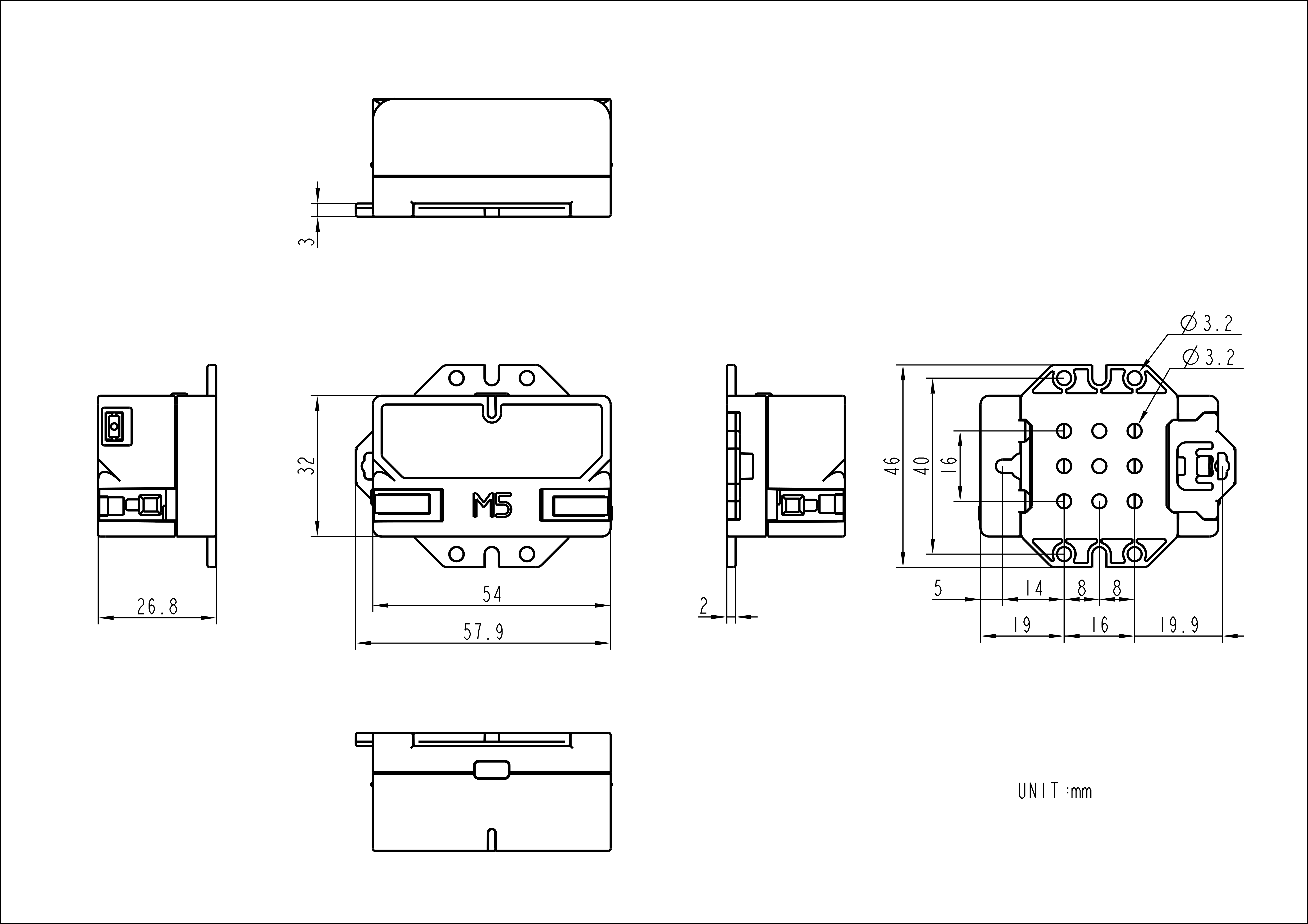
| Product Size | 58.0 x 46.0 x 27.0mm |
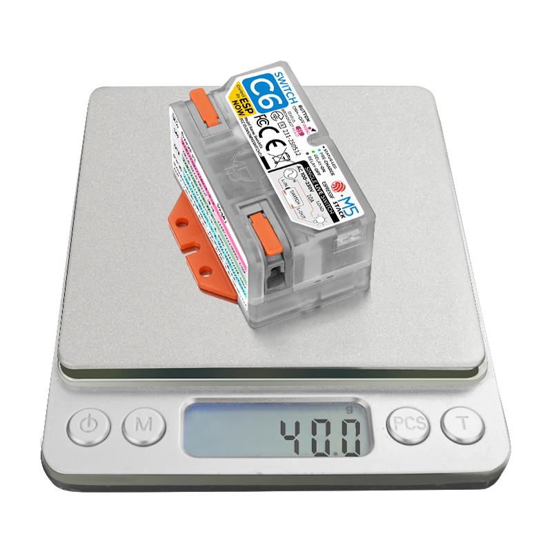
| Product Weight | 40.0g |
| Package Size | 63.0 x 48.0 x 28.5mm |
| Gross Weight | 47.3g |
Learn
Wiring
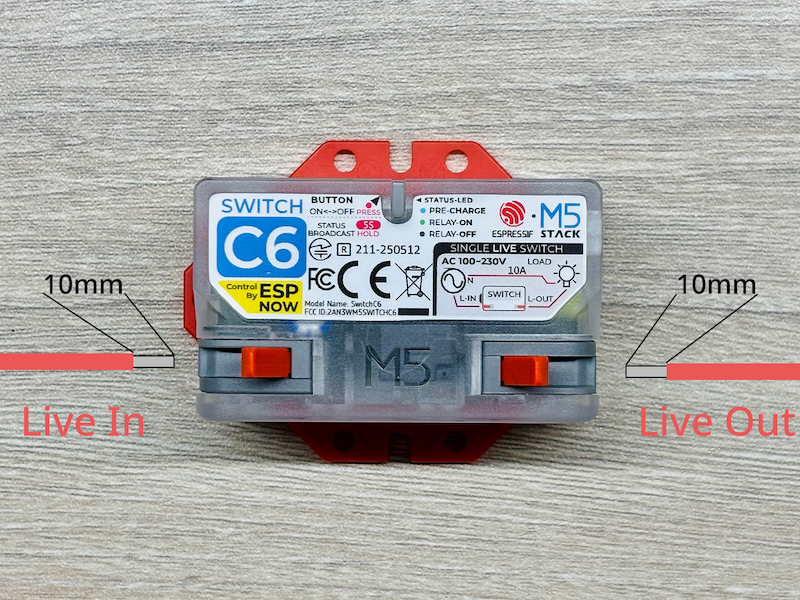
As shown in the sticker information and the above diagram, SwitchC6, as a single-live wire switch, needs to be connected between the live wire power supply and the load appliance. The left L-IN is close to the power source, and the right L-OUT is close to the load. The wires connected to the switch need to expose 10mm of metal, and the wire gauge should match the circuit's maximum load current. When wiring, first open the buckle, fully insert the metal wire end into the opening, and press the buckle tightly.
MAC Address Acquisition

The MAC address (equivalent to the product's unique ID) is shown on the sticker on the back of the product. As shown above, pull the small hook forcefully and lift the cover to see it. In addition, you can also program the master device to scan and read the MAC address included in the status information broadcasted by SwitchC6; the specific method is described in the Arduino development section.
Please note that during development, you need to convert the sticker's XX:XX:XX:XX:XX:XX format into the XXXX-XXXX-XXXX format.
Status Indicator
| Blue Light | Green Light | |
|---|---|---|
| ON | Charging start-up, temporarily unavailable | Switch closed, circuit connected |
| OFF | Charging complete, ready for normal work | Switch open, circuit disconnected |
Button Control
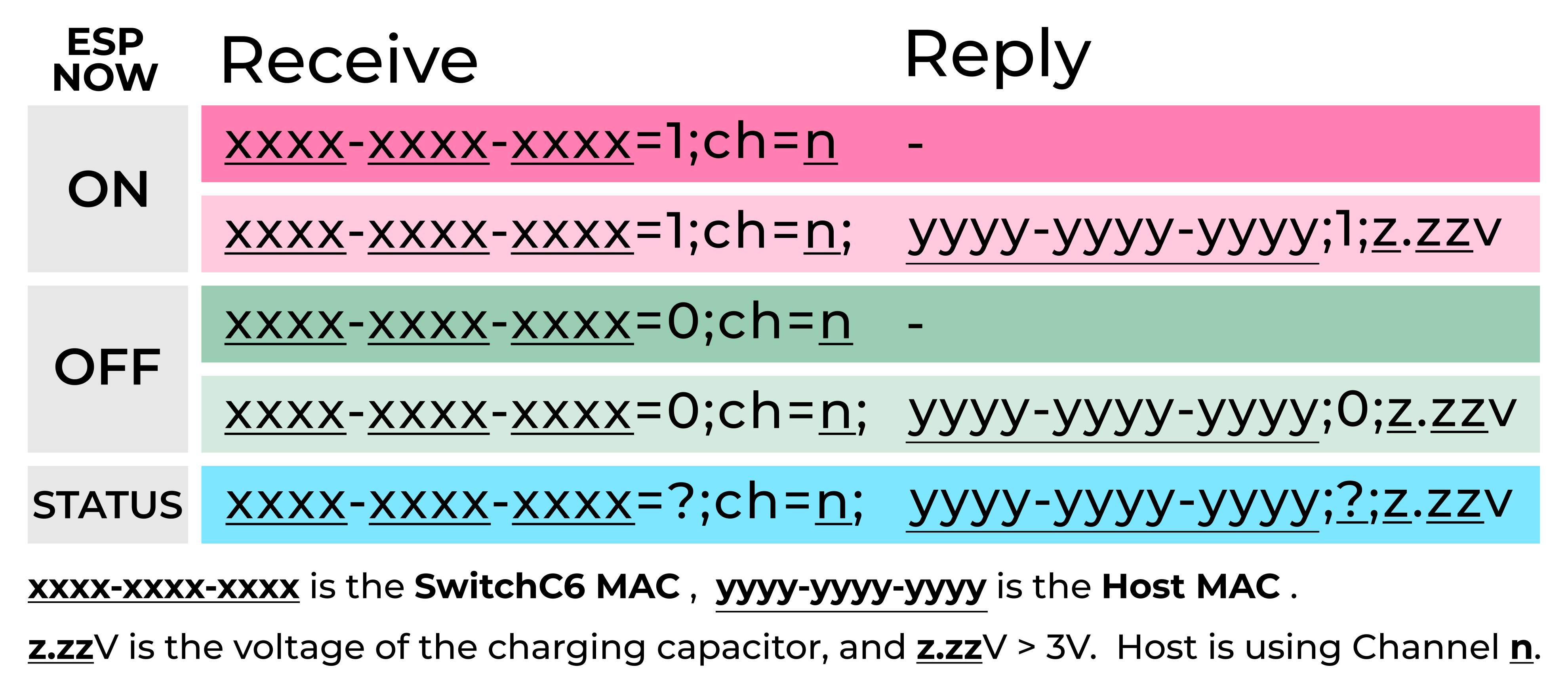
- Short press once: Toggle the switch state, then broadcast status information (own MAC address, channel, new switch state, capacitor voltage, etc.).
- Long press 5s: Broadcast status information (same as above).
Wireless Control
Program the main control device (such as M5Stack CoreS3, etc.) to communicate wirelessly with the SwitchC6 via ESP-NOW, enabling operations such as controlling switches and reading status. For detailed instructions, see Arduino Development Section, UiFlow2 Development Section.
PinMap
SwitchC6
| SwitchC6 | G7 | G14 | G15 | G6 |
|---|---|---|---|---|
| User Button | Button | |||
| Relay Pulse OFF | Relay OFF | |||
| Relay Pulse ON | Relay ON | |||
| EH_12V ADC | ADC |
Model Size
Datasheets
Softwares
Arduino
UiFlow2
Home Assistant
Protocol
Video
- SwitchC6 Product Introduction and Use Cases