Module13.2 4In8Out
SKU:M122


Description
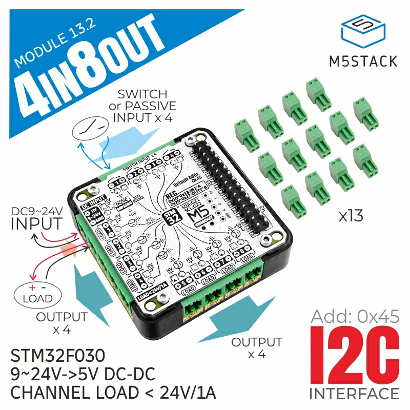
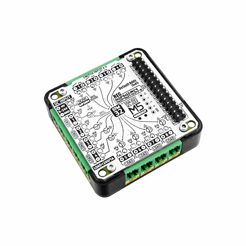
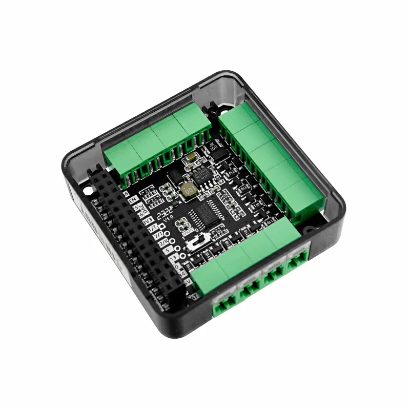
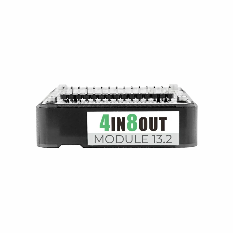
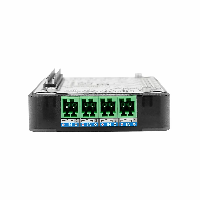
Module13.2 4In8Out is an IO expansion module with 8-channel MOS driven outputs + 4-channel passive contact inputs. It uses an STM32F030 as the I2C IO expansion chip, supports 9 ~ 24V power input, and has a built-in 5V DC-DC conversion circuit.
Features
- Suitable for Basic/Fire/Core2/CoreS3 hosts
- Equipped with STM32F030 as IO expansion chip, communicates with host via I2C, I2C address can be modified by writing to registers
- 8-channel common-positive MOS driving circuit (A3400), can directly drive loads, each channel supports up to 1A, total current not exceeding 8A
- 4-channel common-ground passive contact inputs, cannot be connected to active signals or signals greater than 5V
- Built-in MP1584 9 ~ 24V -> 5V DC-DC circuit
Includes
- 1 x Module13.2 4In8Out
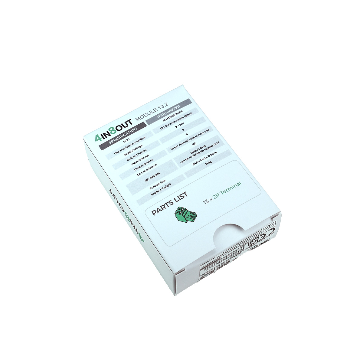
- 13 x 2P Terminal
Applications
- Multi-channel load driving (relay, air valve, unidirectional motor, signal indicator lights, etc.)
- Limit switch, button detection
Specifications
| Specification | Parameter |
|---|---|
| MCU | STM32F030F4P6 |
| Communication Interface | I2C Communication @0x45 |
| Supply Voltage | 9 ~ 24V |
| Output Channel | 8 |
| Input Channel | 4 |
| Output Current | 1A per channel, total current ≤ 8A |
| Communication | I2C |
| I2C Address | Default 0x45, can be modified via register 0xFF |
| Product Size | 54.0 x 54.0 x 19.7mm |
| Product Weight | 21.9g |
| Package Size | 80.0 x 55.0 x 28.0mm |
| Gross Weight | 52.5g |
Learn
Function of the Onboard Toggle Switch
The red box in the figure below is the Boot0 control toggle switch. Switching to position 1 (high) enters firmware flashing mode. Switching to position 0 (low) reads user program from flash memory, i.e., normal operating mode.
.png)
Schematics
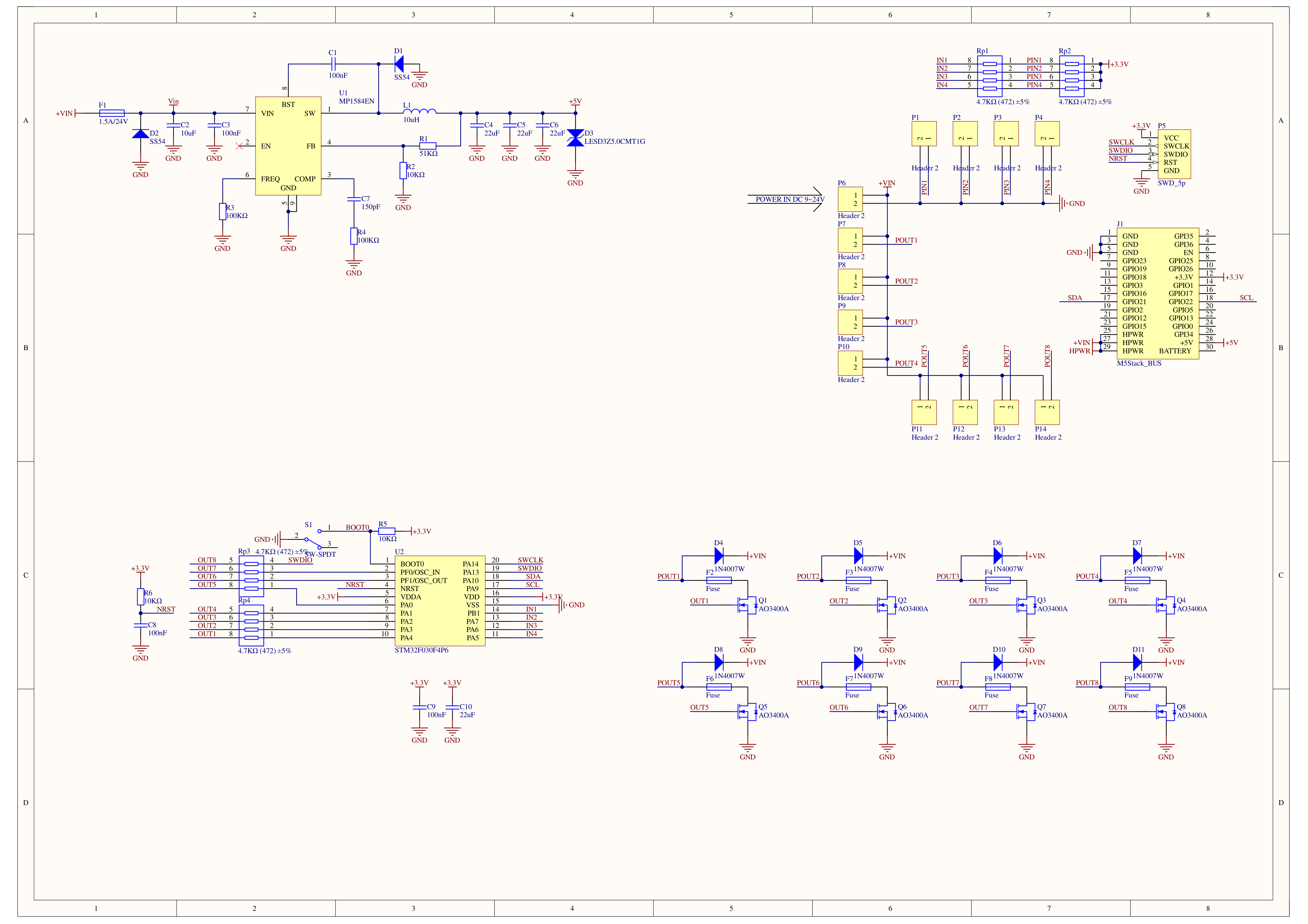
1/1

PinMap
M5-Bus
| PIN | LEFT | RIGHT | PIN |
|---|---|---|---|
| GND | 1 | 2 | |
| GND | 3 | 4 | |
| GND | 5 | 6 | |
| 7 | 8 | ||
| 9 | 10 | ||
| 11 | 12 | 3V3 | |
| 13 | 14 | ||
| 15 | 16 | ||
| SDA | 17 | 18 | SCL |
| 19 | 20 | ||
| 21 | 22 | ||
| 23 | 24 | ||
| HPWR | 25 | 26 | |
| HPWR | 27 | 28 | 5V |
| HPWR | 29 | 30 |
Model Size
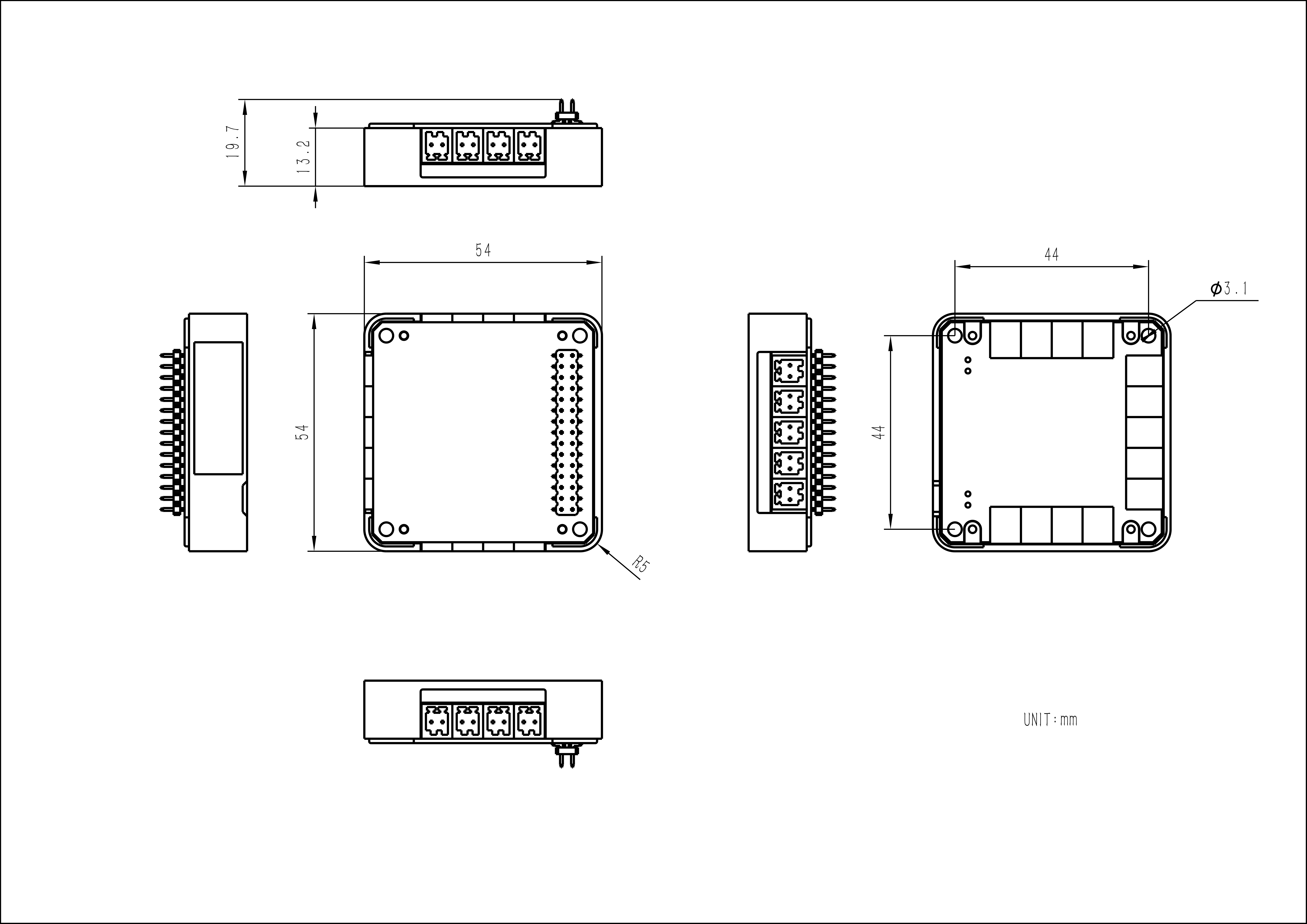
Softwares
Arduino
#include <M5Stack.h>
#include "MODULE_4IN8OUT.h"

MODULE_4IN8OUT module;

int _I2C_dev_scan();

void setup() {
    M5.begin(1,1,1,1);  // Init M5Stack.

    // while (1) {
    //     _I2C_dev_scan();
    //     delay(1000);
    // }


    while (!module.begin(&Wire, 21, 22, MODULE_4IN8OUT_ADDR)) {
        Serial.println("4IN8OUT INIT ERROR");
        M5.Lcd.println("4IN8OUT INIT ERROR");
        _I2C_dev_scan();
        delay(1000);
    };
    Serial.println("4IN8OUT INIT SUCCESS");
}

// void loop() {

// }

long interval = 0;
bool level    = false;

void loop() {
    for (uint8_t i = 0; i < 4; i++) {
        if (module.getInput(i) != 1) {
            M5.Lcd.fillRect(60 + 60 * i, 0, 25, 25, TFT_GREEN);
        } else {
            M5.Lcd.fillRect(60 + 60 * i, 0, 25, 25, TFT_RED);
        }
        M5.Lcd.drawString("IN" + String(i), 40 + 60 * i, 5);
    }
    M5.Lcd.drawString("4IN8OUT MODULE", 60, 80, 4);
    if (millis() - interval > 1000) {
        interval = millis();
        level    = !level;
        for (uint8_t i = 0; i < 8; i++) {
            module.setOutput(i, level);
            if (level) {
                M5.Lcd.fillRect(20 + 35 * i, 200, 25, 25, TFT_BLUE);
            } else {
                M5.Lcd.drawRect(20 + 35 * i, 200, 25, 25, TFT_BLUE);
            }
            M5.Lcd.drawString("OUT" + String(i), 18 + 35 * i, 180);
        }
    }
    delay(500);
}


int _I2C_dev_scan() {
    uint8_t error, address;
    int nDevices;

    Serial.println("[I2C_SCAN] device scanning...");

    nDevices = 0;
    for (address = 1; address < 127; address++ ) {
        Wire.beginTransmission(address);
        error = Wire.endTransmission();

        if (error == 0) {
            Serial.print("[I2C_SCAN]: device found at address 0x");
            if (address < 16)
                Serial.print("0");
            Serial.print(address, HEX);
            Serial.println(" !");

            nDevices++;
        }
        else if (error == 4) {
            Serial.print("[I2C_SCAN]: unknown error at address 0x");
            if (address < 16)
                Serial.print("0");
            Serial.println(address, HEX);
        }
    }

    Serial.printf("[I2C_SCAN]: %d devices were found\n", nDevices);
    return nDevices;
}UiFlow1
UiFlow2
Protocol
