
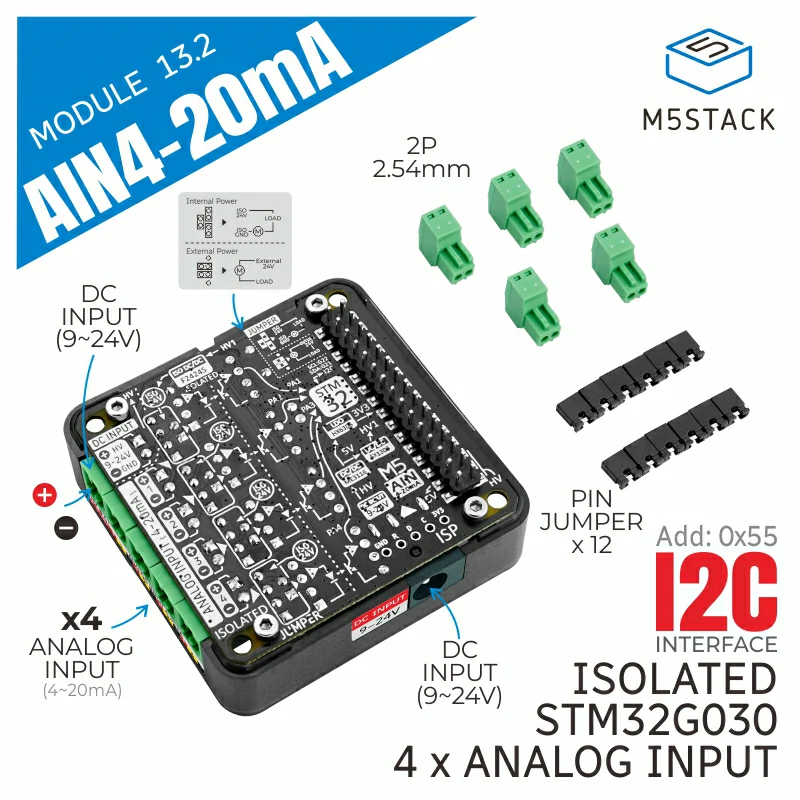
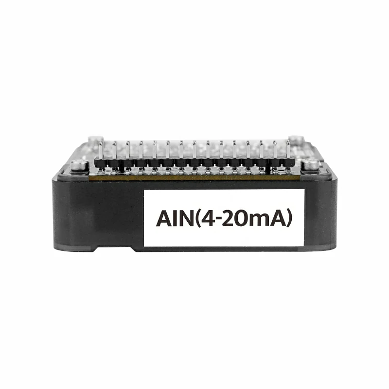
Module13.2 AIN4-20mA
SKU:M133
Description
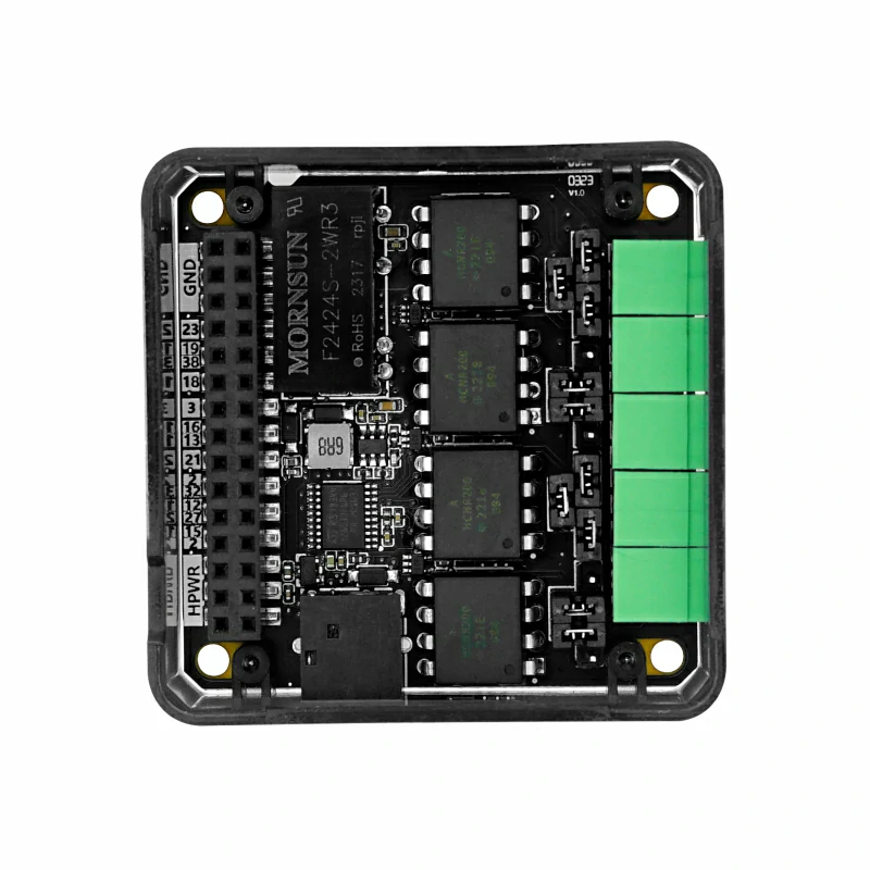
Module13.2 AIN4-20mA is a four-channel 4 ~ 20 mA current-type analog acquisition module. It uses the STM32G030F6 main control chip and a dedicated isolated acquisition chip, communicating with the M5 host via I2C. It supports switching between internal or external power supply through jumper caps. The onboard power isolation chip and built-in operational amplifier circuit ensure accurate measurement of external current sensors and the accuracy of the signal and system safety. The DC-JACK interface and corresponding DC-DC boost circuit provide power to the entire device. It is suitable for power system equipment monitoring, motor control, energy management, automation, and industrial process control.
Features
- STM32G030F6® 32-bit Cortex®-M0+ CPU
- I2C communication
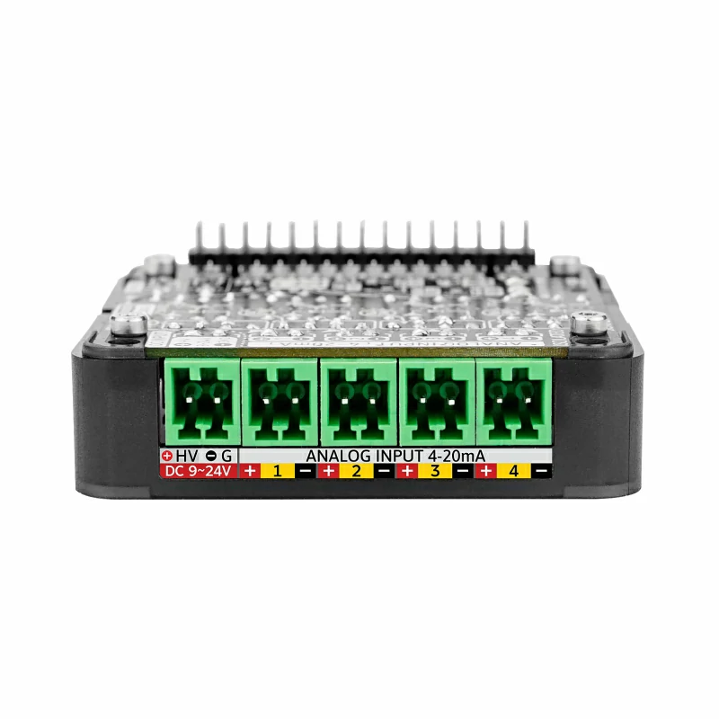
- Supports four 2-wire or 4-wire sensors, switchable via jumper caps
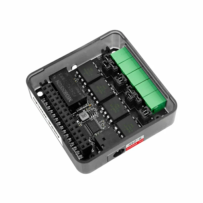
- Built-in electrical isolation chip
- Supports Arduino, UIFlow, and other programming platforms
Includes
- 1 × AIN4-20mA Module 13.2
- 12 × Jumper caps
- 5 × KF2EDGK-2.54-2P connection terminals
Applications
- Power system equipment monitoring
- Motor control
- Energy management
- Automation and industrial process control
Specifications
| Specification | Parameter |
|---|---|
| MCU | STM32G030F6P6 |
| Signal Isolation Chip | HCNR200 |
| Power Isolation Chip | F2424S-2WR3 |
| Operational Amplifier | SGM321YC5/TR |
| Communication Interface | I2C Communication @ 0x55 |
| IN+ and IN- Input Impedance | 200Ω |
| Channel Interface Specification | KF2EDGR-2.54-2P |
| Operating Temperature | 0 ~ 40°C |
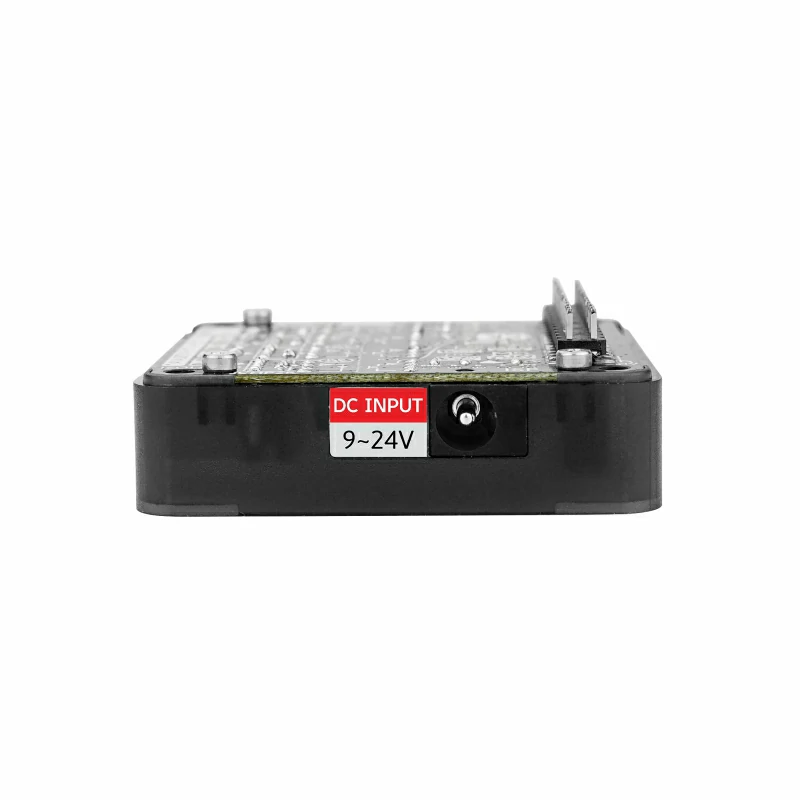
| External DC Power Supply | DC 9 ~ 24V |
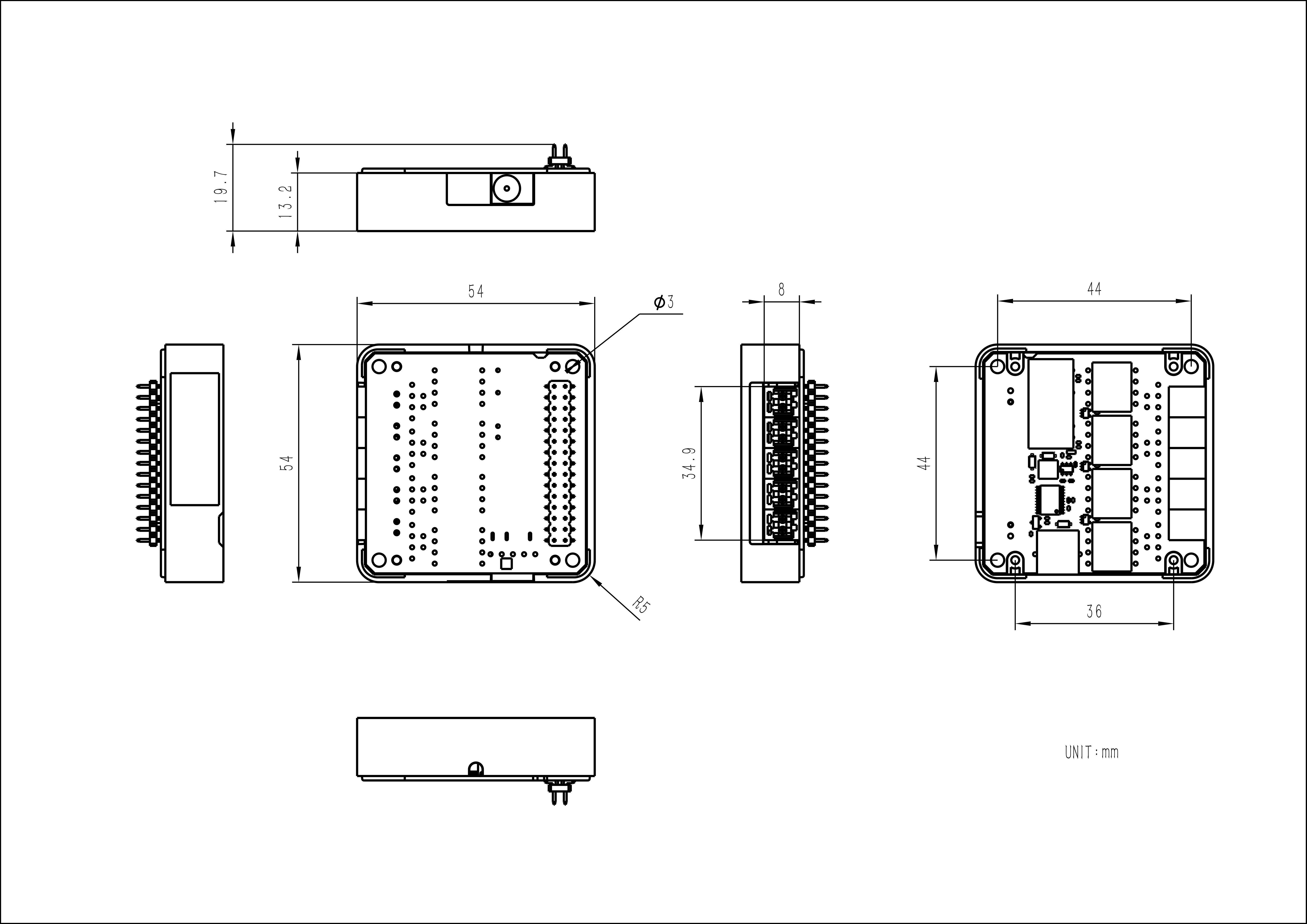
| Product Size | 54.0 x 54.0 x 13.0mm |
| Product Weight | 26.9g |
| Package Size | 95.0 x 65.0 x 25.0mm |
| Package Weight | 51.7g |
Learn
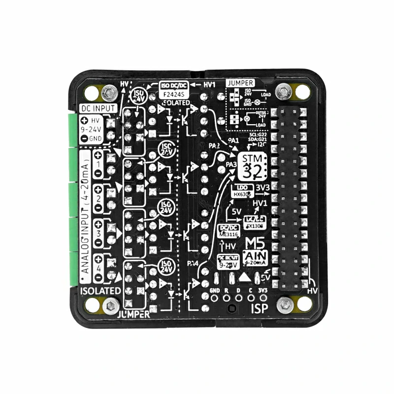
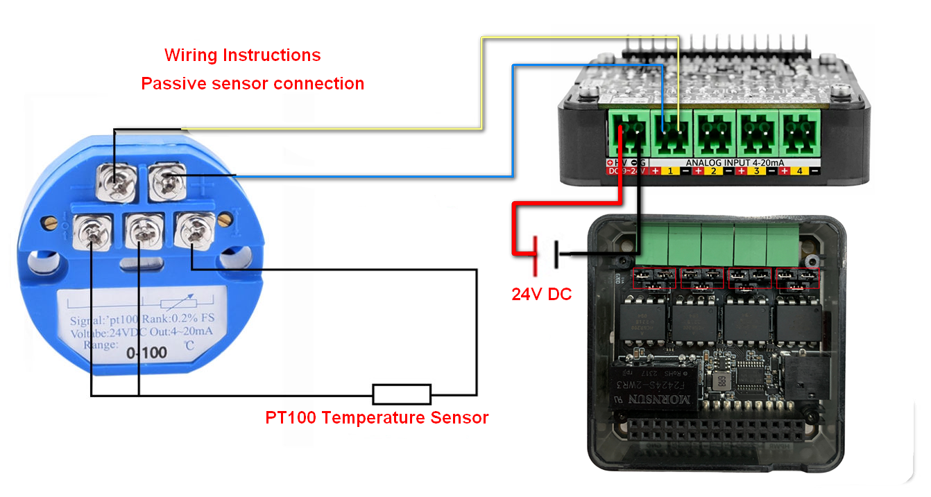
Jumper Cap Connection and Instructions
- When using a passive current-type sensor, please connect the DC 24V power supply input, connect the sensor signal to IN+ and IN-, and adjust the jumper cap as shown below:
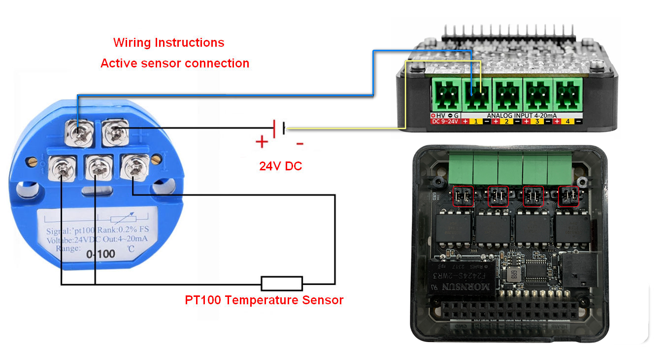
- When using an active current-type sensor, connect the sensor signal to IN+ and IN-, and adjust the jumper cap as shown below:
Schematics
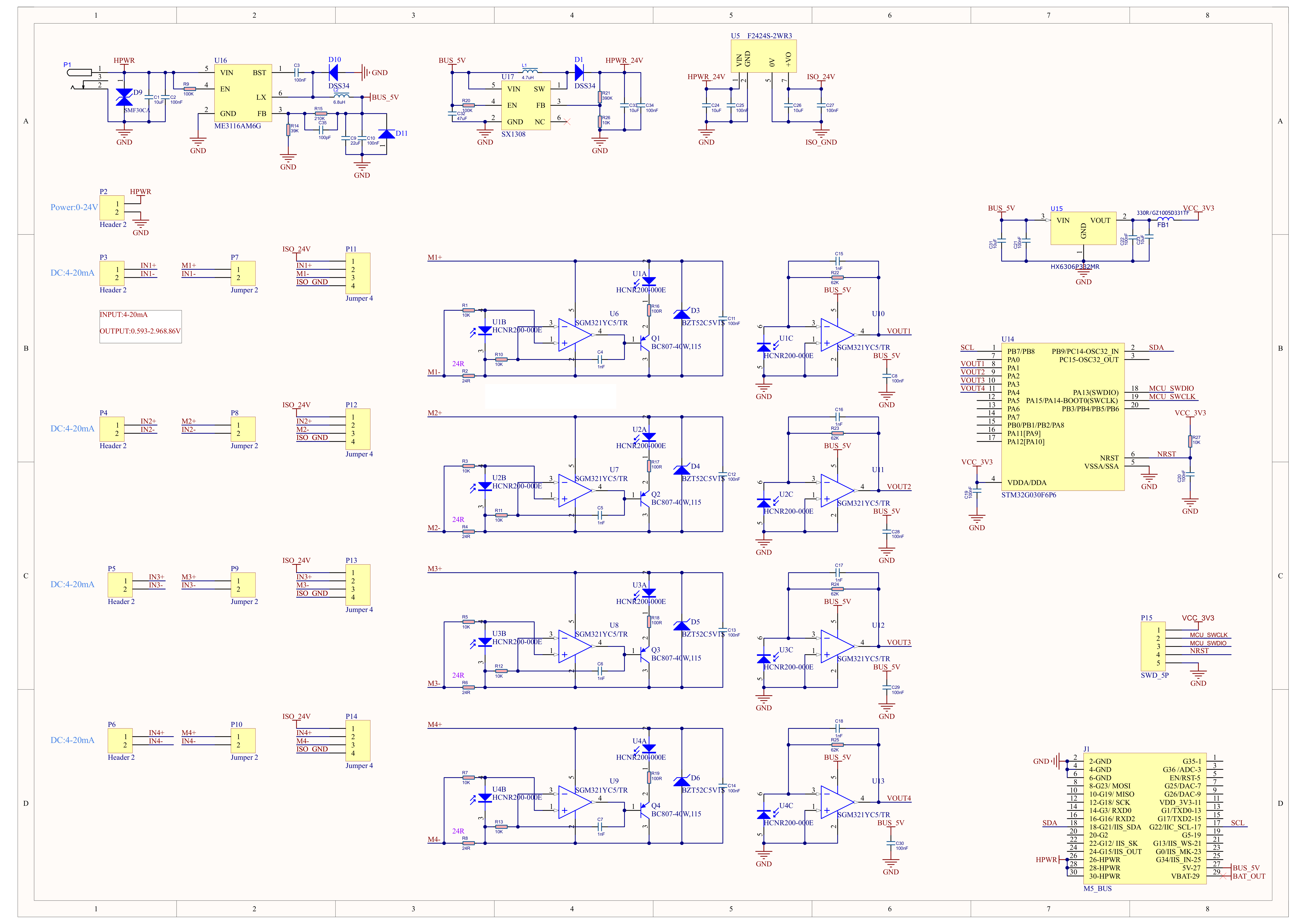
1/1
PinMap
M5-Bus
| PIN | LEFT | RIGHT | PIN |
|---|---|---|---|
| GND | 1 | 2 | |
| GND | 3 | 4 | |
| GND | 5 | 6 | |
| 7 | 8 | ||
| 9 | 10 | ||
| 11 | 12 | ||
| 13 | 14 | ||
| 15 | 16 | ||
| SDA | 17 | 18 | SCL |
| 19 | 20 | ||
| 21 | 22 | ||
| 23 | 24 | ||
| HPWR | 25 | 26 | |
| HPWR | 27 | 28 | BUS_5V |
| HPWR | 29 | 30 | BAT_OUT |
Model Size
Datasheets
Softwares
Arduino
UiFlow1
UiFlow2
Internal Firmware
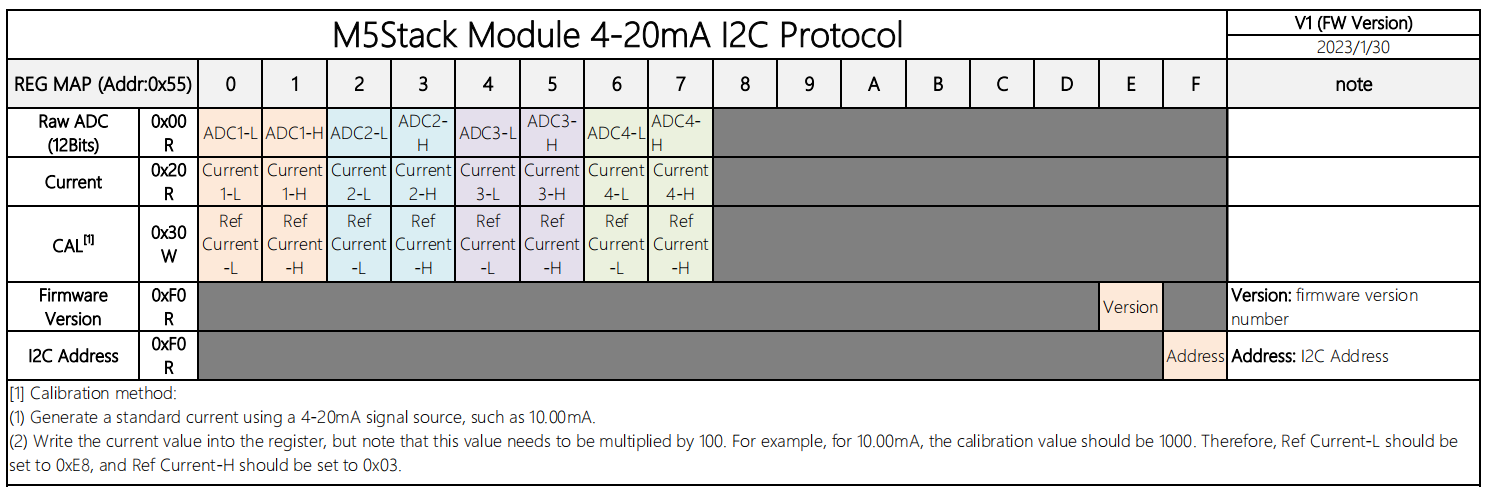
Protocol
Video
Page Tools