CoreMatrix
SKU:C158
Description
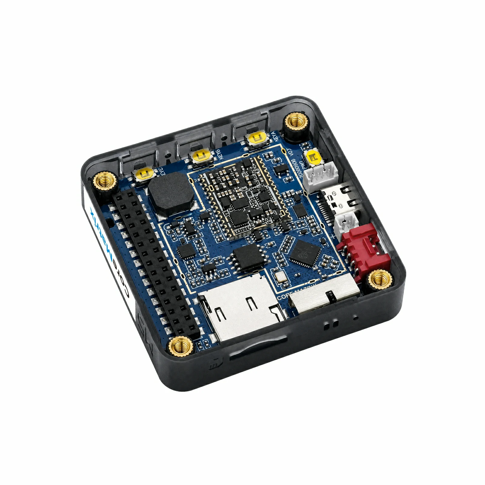
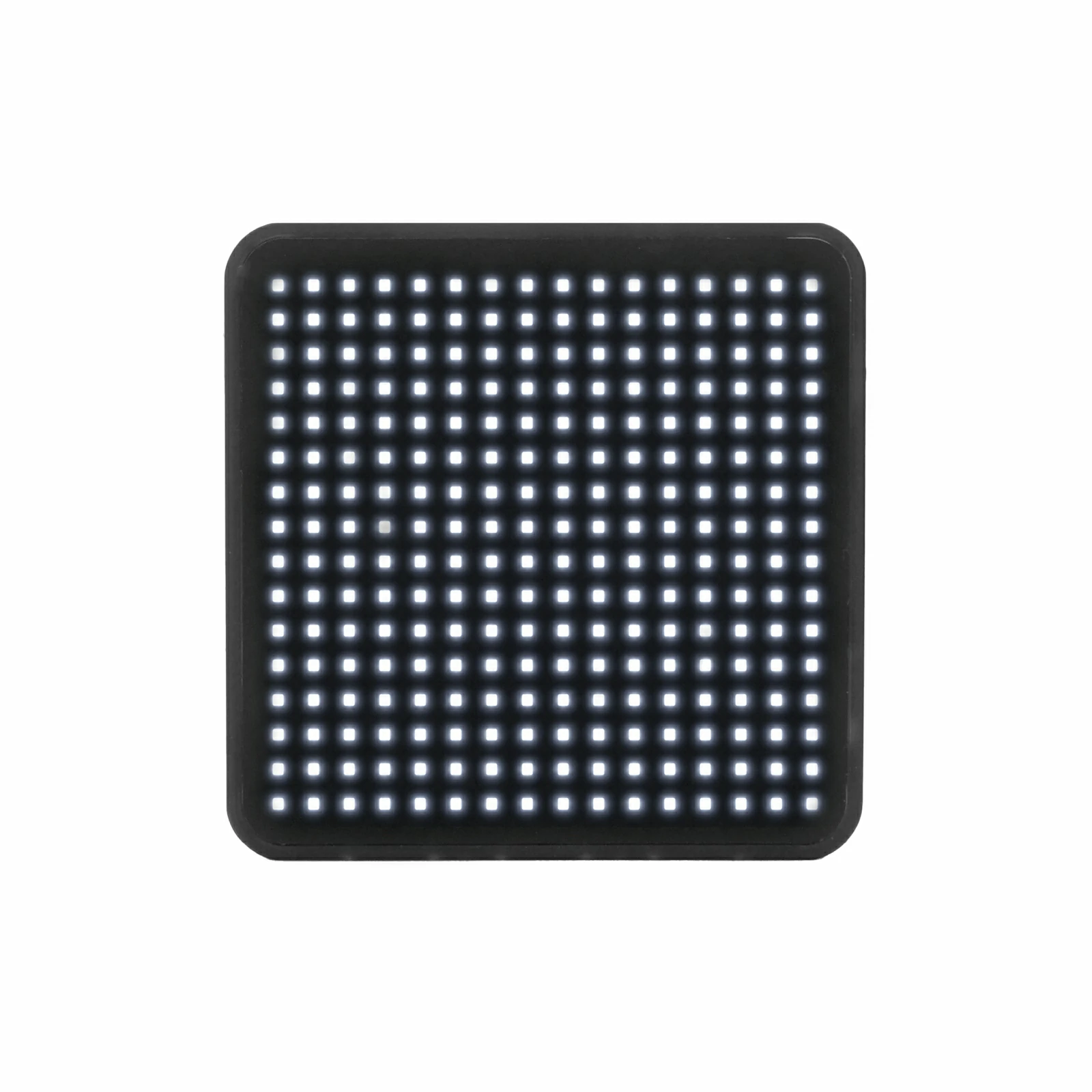
CoreMatrix is an IoT controller featuring a 16 x 16 LED matrix display. It is powered by the ESP32-C61HR8 core, which uses a 32-bit RISC-V single-core processor running at 160MHz, supports 2.4 GHz Wi-Fi 6, and includes 16MB of Flash and 8MB of PSRAM.
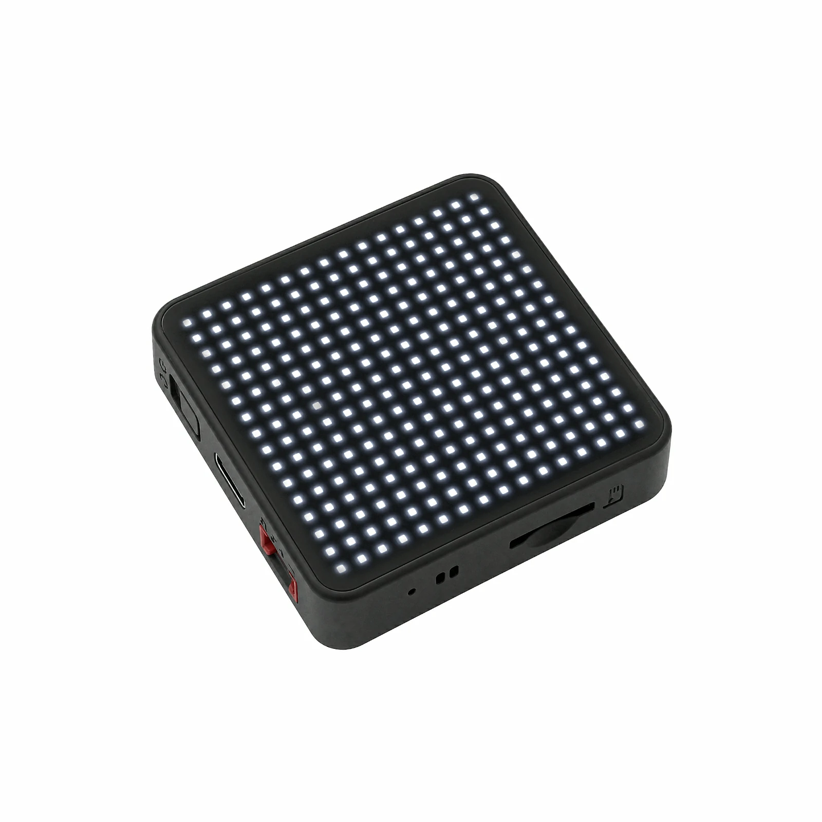
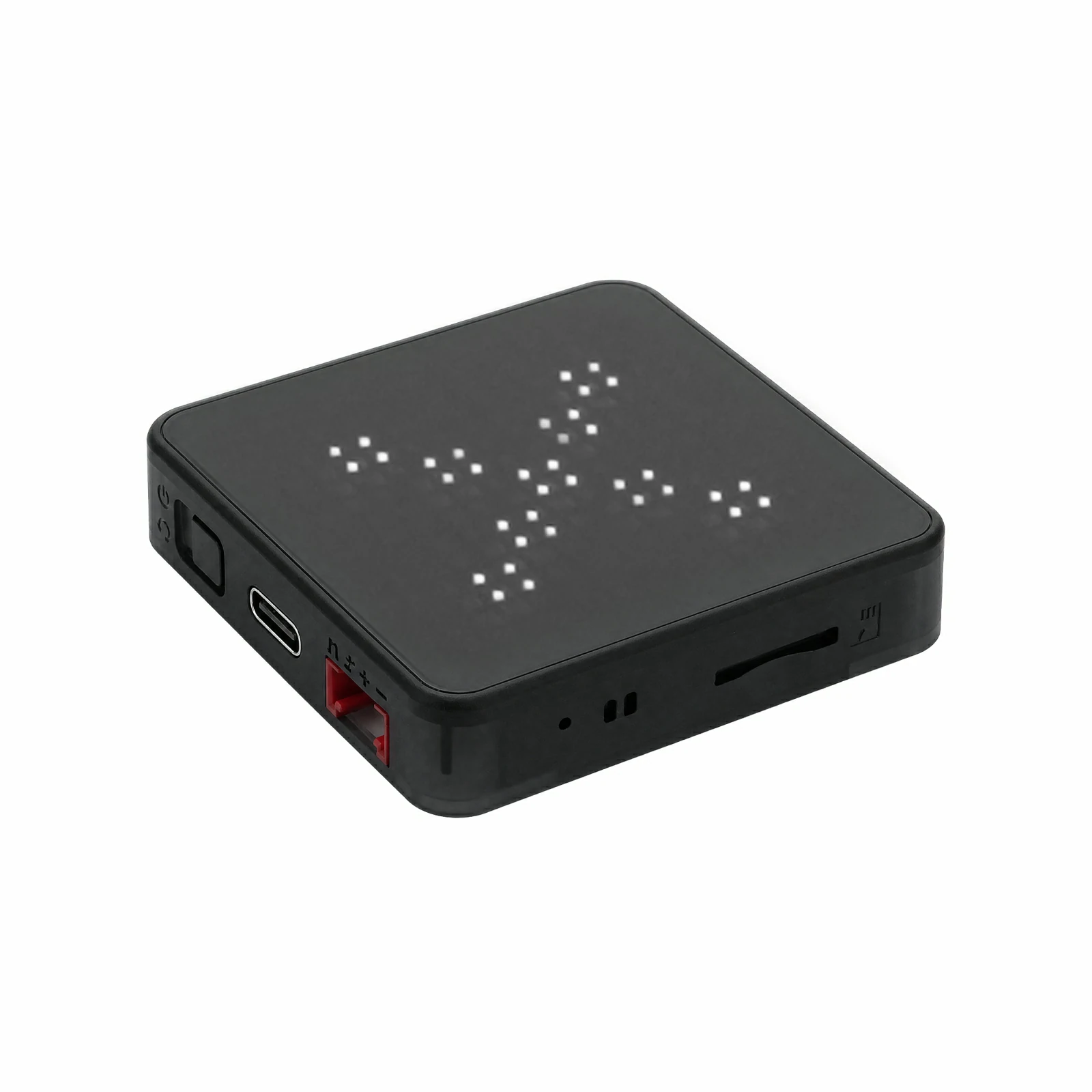
The front panel features a 16 x 16 white LED matrix that displays device status, event reminders, and interactive feedback through icons and simple animations. An onboard BMI270 6-axis IMU supports motion detection and orientation-based interaction.
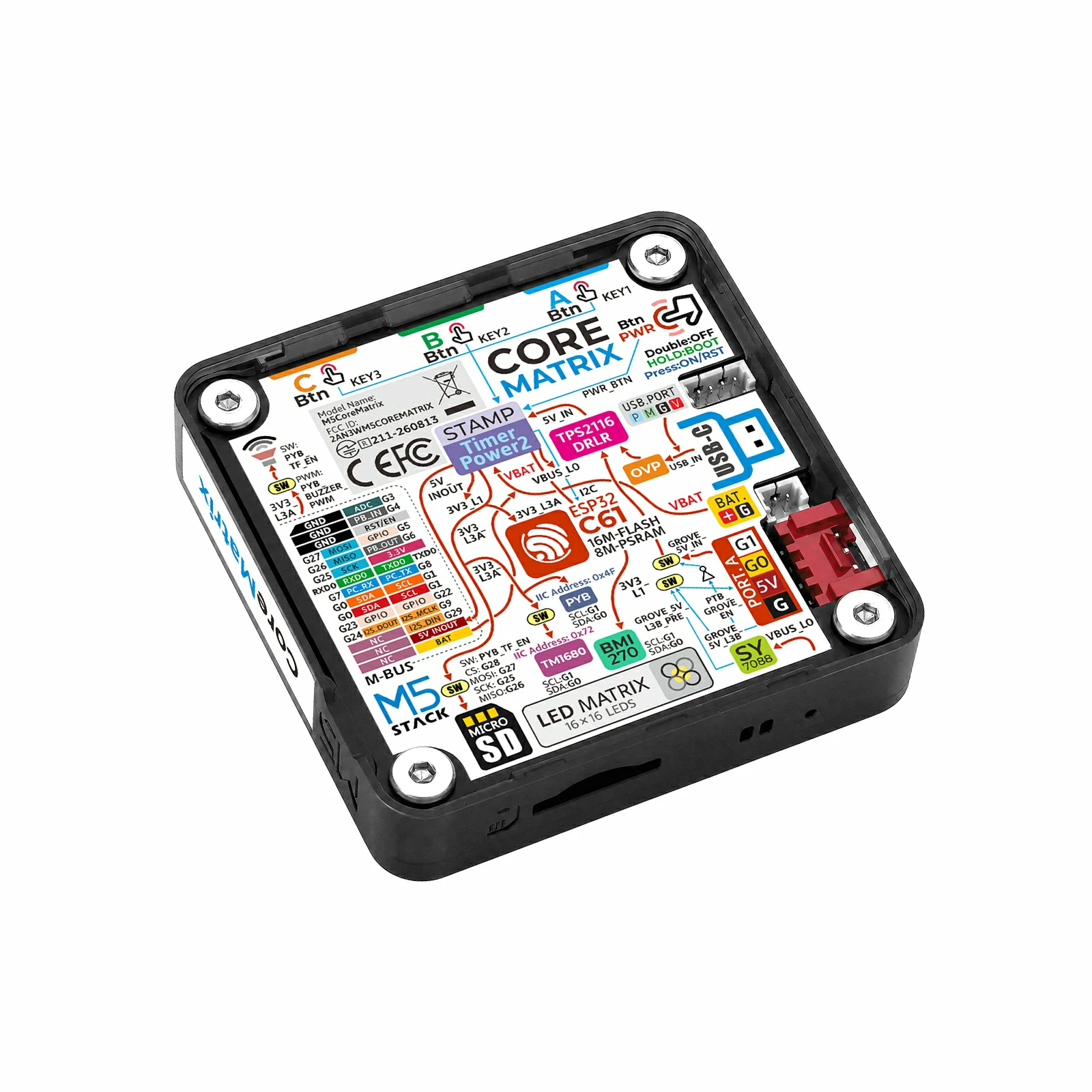
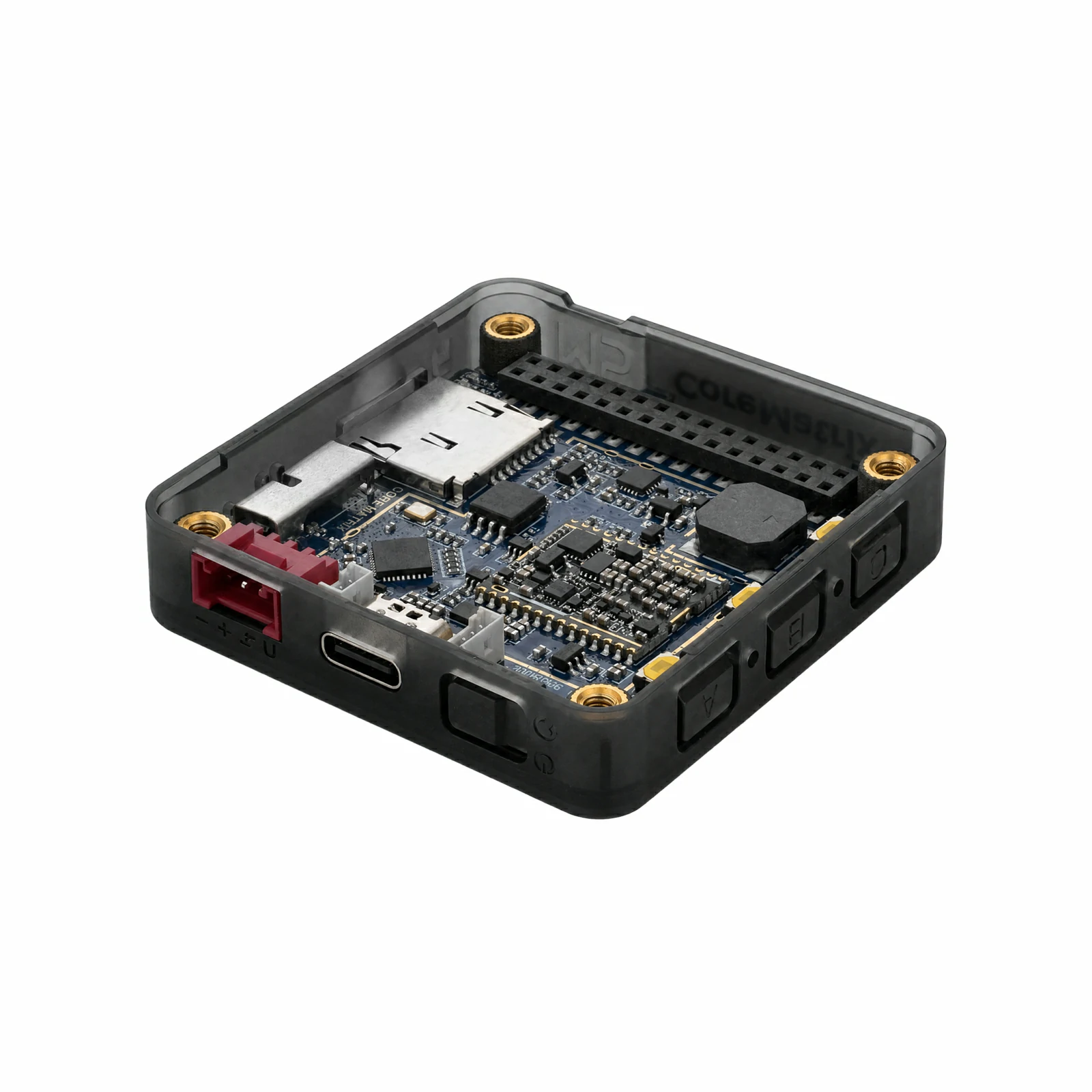
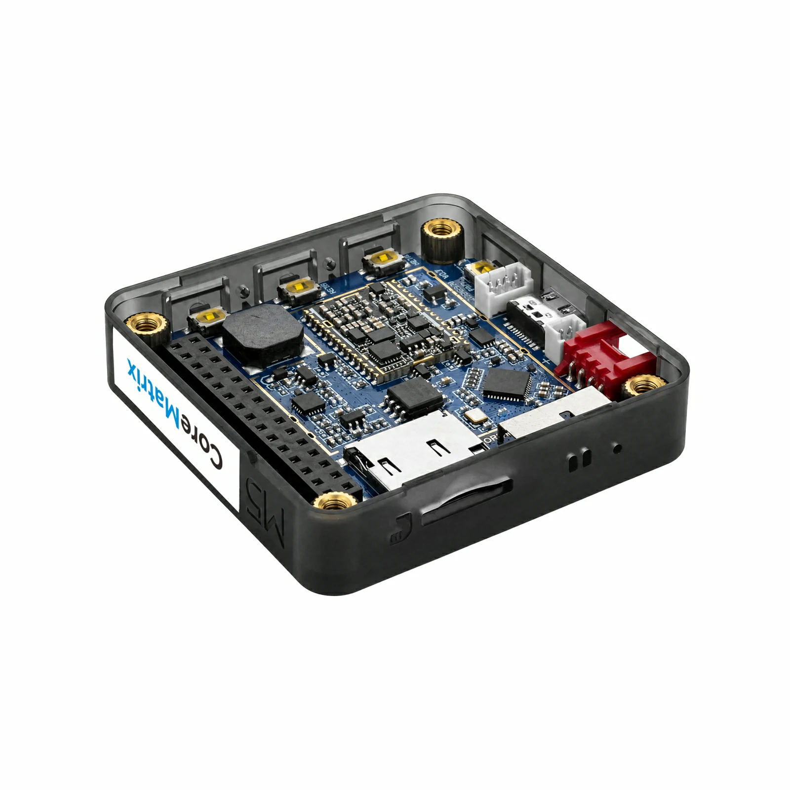
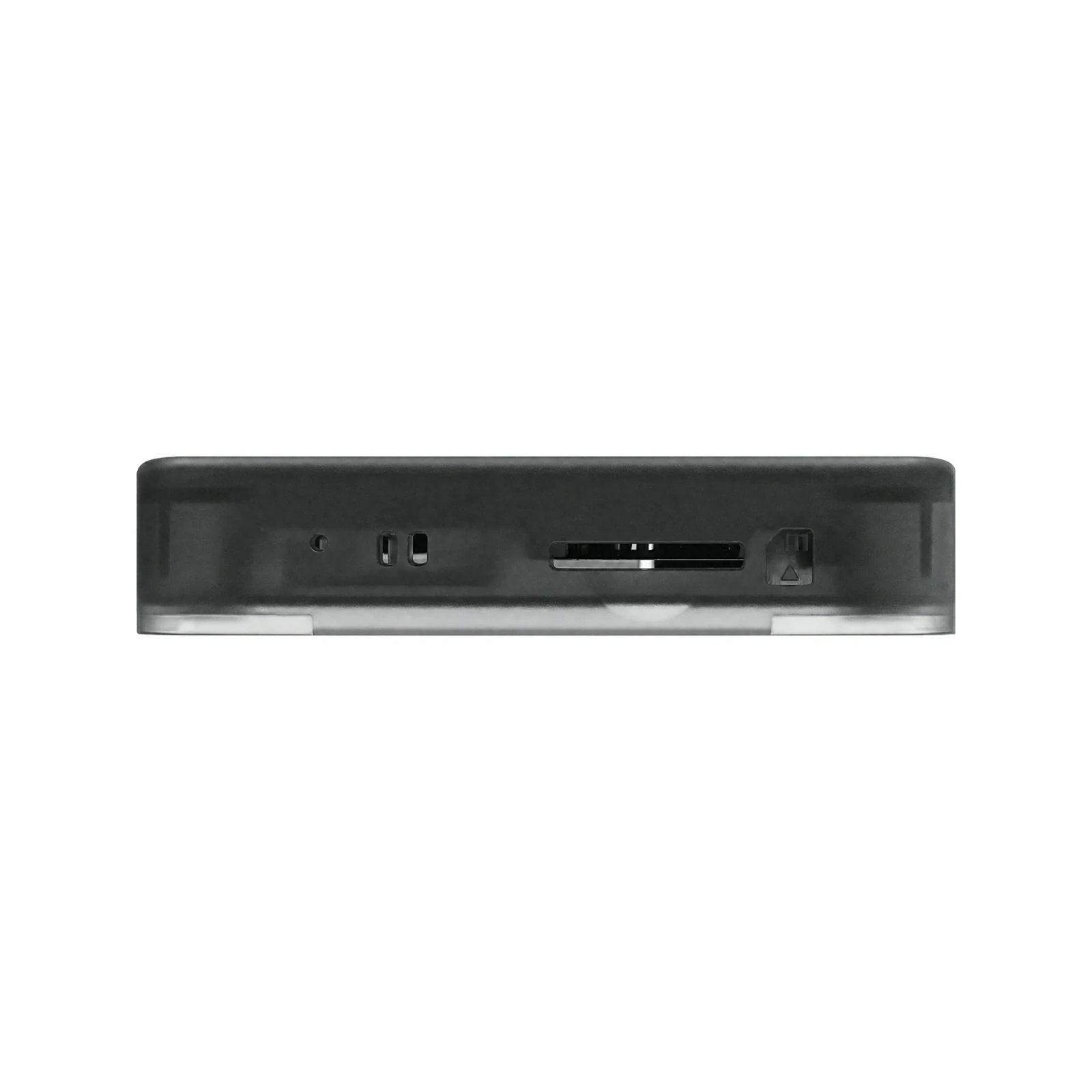
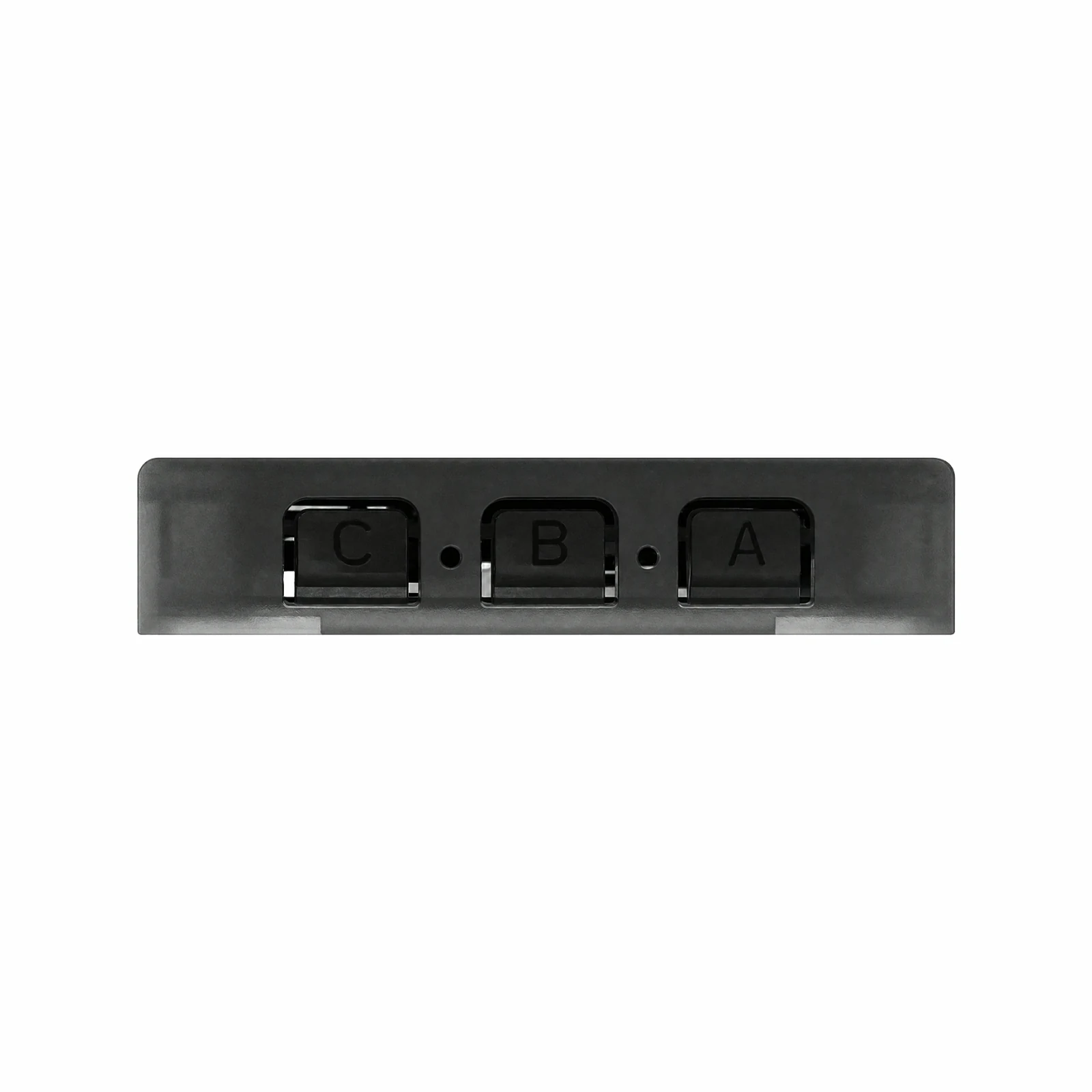
The device also integrates a microSD card slot, a passive buzzer, three user buttons, and a power button. Peripheral control, charging management, and multi-level power management are handled by the M5IOE1 and Stamp Timer Power2 (M5PM1).
The onboard M5-Bus and HY2.0-4P Grove interfaces allow connection to M5Stack Modules and other sensor devices, making the device suitable for pixel icon and animation display, sensor data acquisition, device status indication, and IoT interaction applications.
Tutorial
This tutorial introduces how to control the CoreMatrix device using the UiFlow2 graphical programming platform.
This tutorial will introduce how to program and control the CoreMatrix device via Arduino IDE.
Features
- ESP32-C61HR8 core controller:
- 16MB Flash
- 8MB PSRAM
- 2.4 GHz Wi-Fi 6
- LED matrix and sensors:
- 16 x 16 white LED matrix driven by TM1680
- BMI270 6-axis IMU with interrupt wake-up support
- Human-machine interaction:
- Onboard passive buzzer
- 3x user buttons + 1x power button
- Power system:
- Multi-level power management via Stamp Timer Power2 (M5PM1) + M5IOE1
- Onboard battery power connector
- Expansion:
- microSD card slot
- M5-Bus expansion interface
- HY2.0-4P Grove expansion interface
- MX1.25-4P USB expansion interface
Includes
- 1 x CoreMatrix
- 1 x Hex Key L-Shape 2.0mm
Applications
- Pixel icon and animation display
- Sensor data acquisition
- IoT interaction applications
- Embedded interactive device development
Specifications
| Specification | Parameter |
|---|
| SoC | ESP32-C61HR8 @ RISC-V® 32-bit single-core processor, 160MHz |
| Flash | 16MB |
| PSRAM | 8MB Quad |
| Wireless Connectivity | 2.4 GHz Wi-Fi 6 |
| LED Matrix | 16 x 16 white LED matrix |
| LED Driver | TM1680 |
| IMU | BMI270 |
| Power Management | Stamp Timer Power2 (M5PM1) + M5IOE1 |
| Storage Expansion | microSD card |
| Buzzer | Onboard passive buzzer @ MLT-8530 |
| Buttons | Power button, KEY1 (BtnA), KEY2 (BtnB), KEY3 (BtnC) |
| Input Power | USB (DC 5V) / Battery (DC 3.7V) / M5-Bus (DC 5V IN/OUT) |
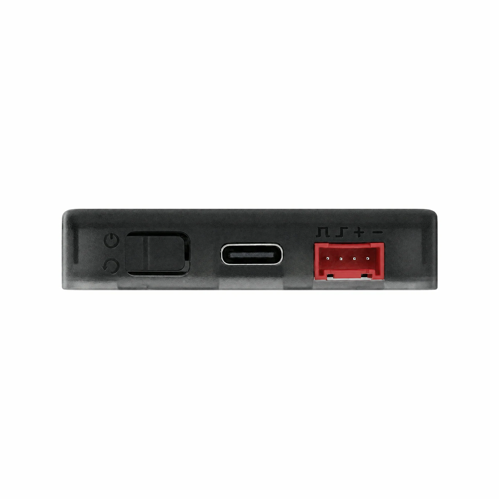
| Communication Interface | 1 x USB Type-C, 1 x HY2.0-4P, 1 x MX1.25-4P |
| Charging Current | 650mA / 180mA, selectable via CHG_PROG |
| Battery Connector Spec | MX1.25-2P |
| Grove Interface Load Capacity | No load: 5V
Full load: 4.79V@470mA |
| Power Consumption | Shutdown state: DC 4.2V@8.21uA
Full load state: DC 4.2V@128.06mA |
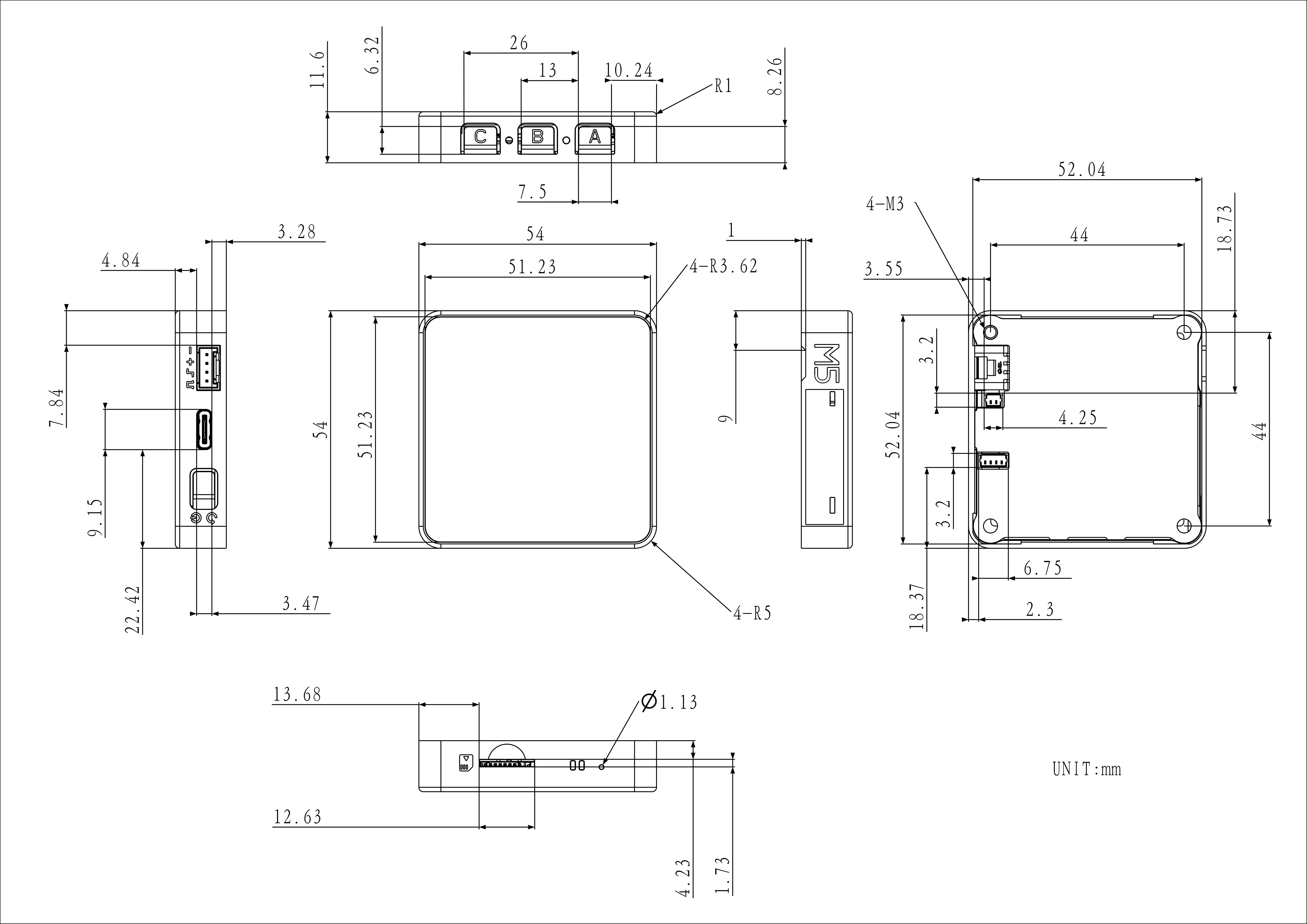
| Product Size | 54.0 x 54.0 x 11.6mm |
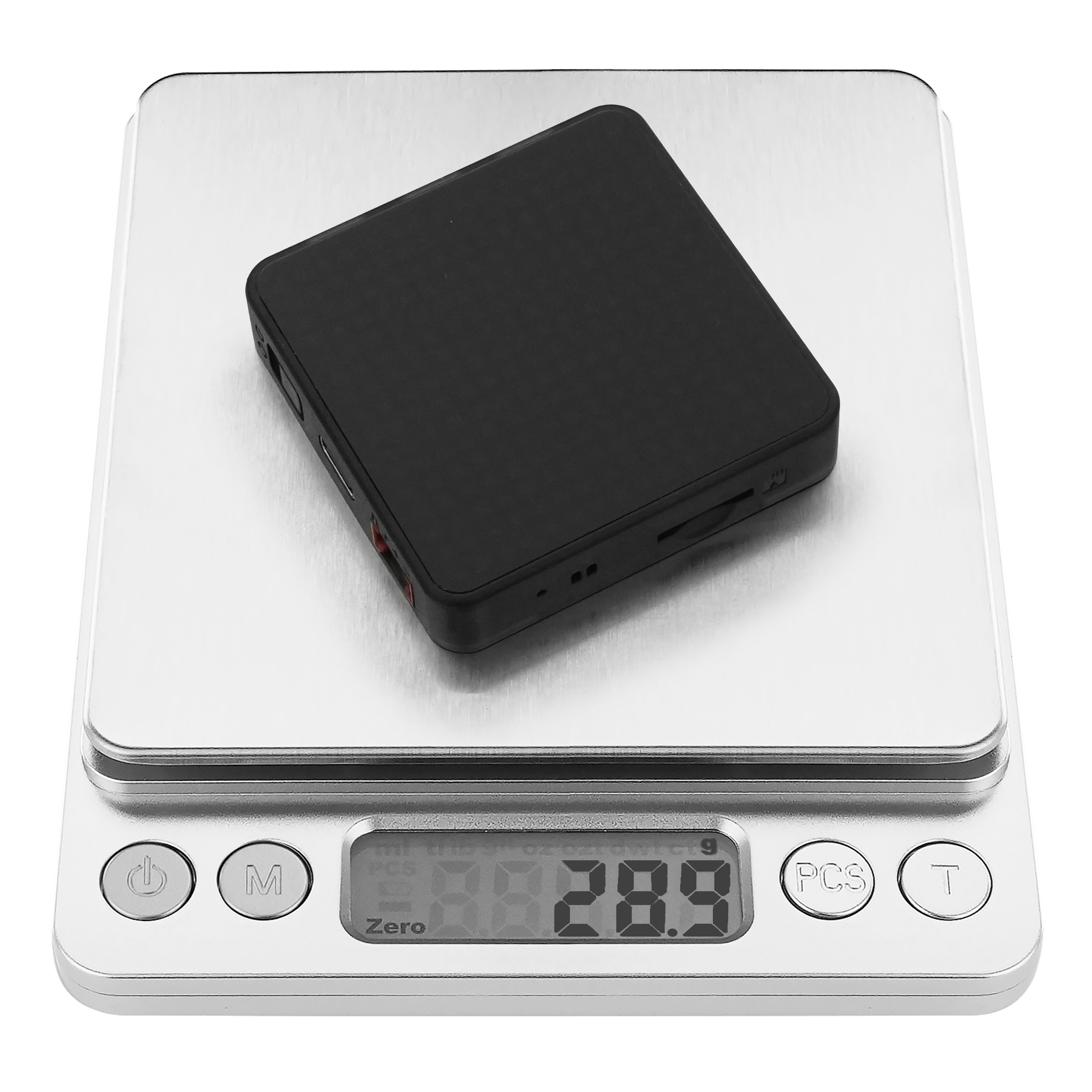
| Product Weight | 28.9g |
| Package Size | 132.0 x 95.0 x 16.0mm |
| Gross Weight | 45.1g |
Learn
Power On/Off
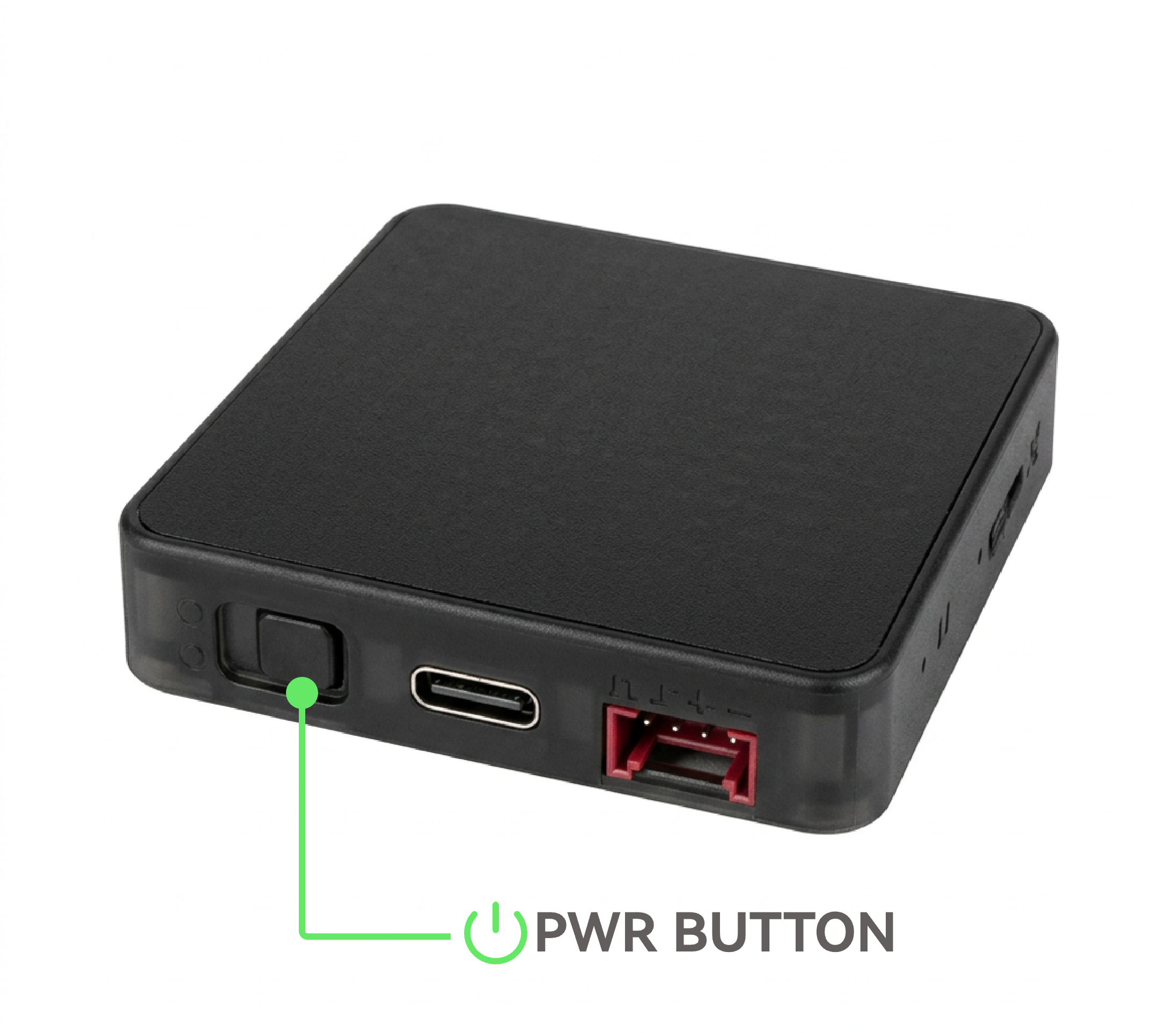
- Single click the power button: Power on / Reset
- Double-click the power button: Power off
Enter Download Mode
Under normal circumstances, the device can be flashed with programs directly via the USB cable. During development and debugging, if an abnormal program flash occurs, long-press the power button to force entry into download mode.
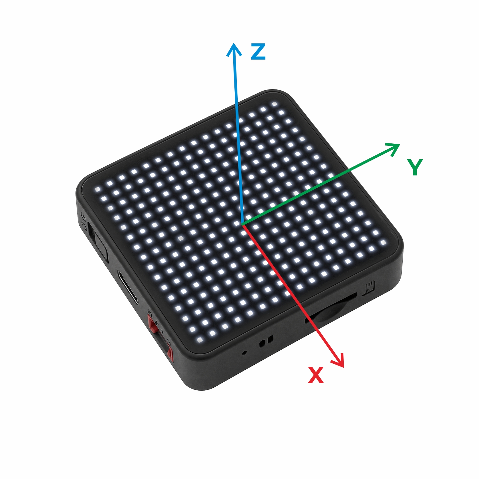
IMU Triaxial Direction Schematic Diagram
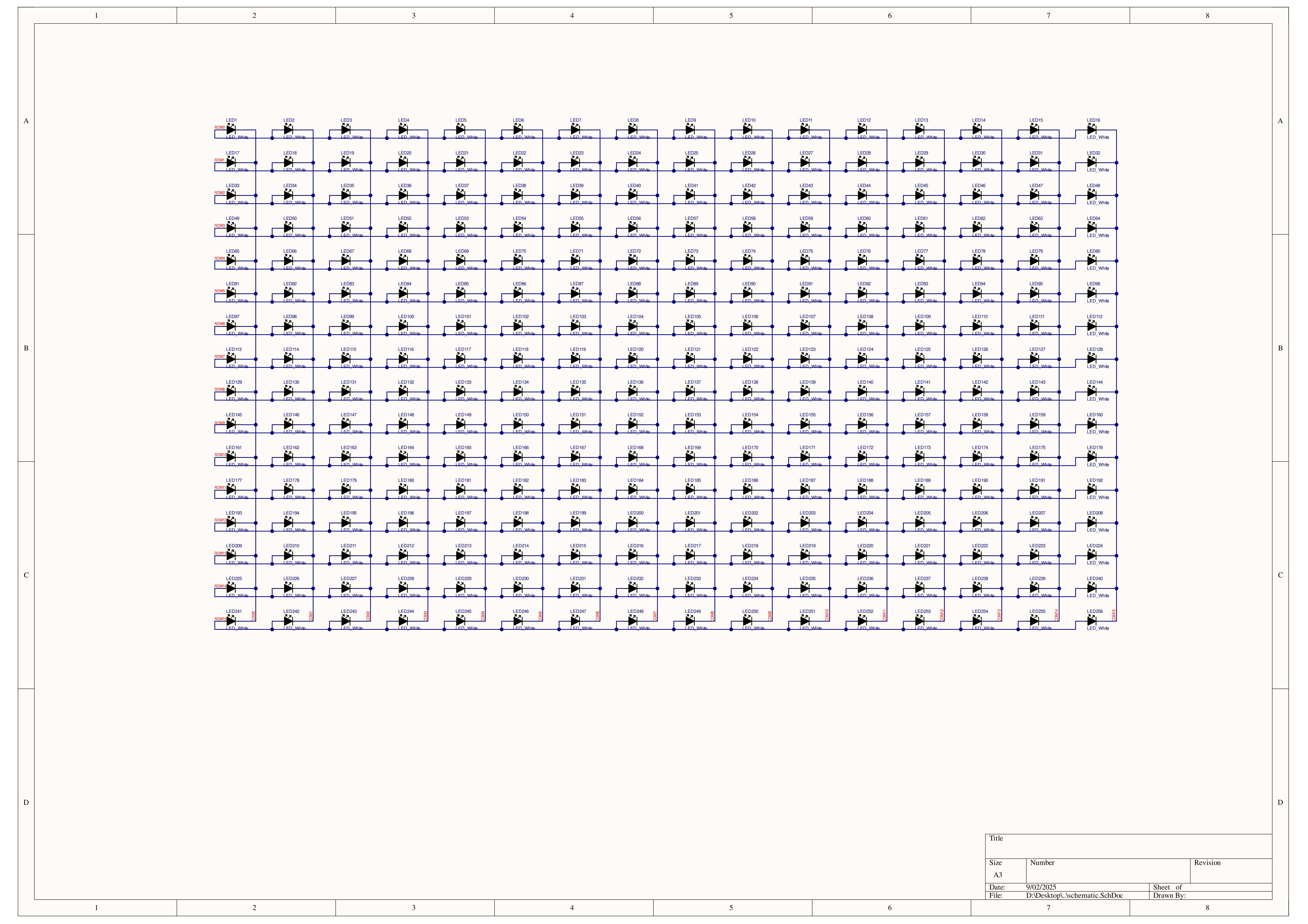
Schematics
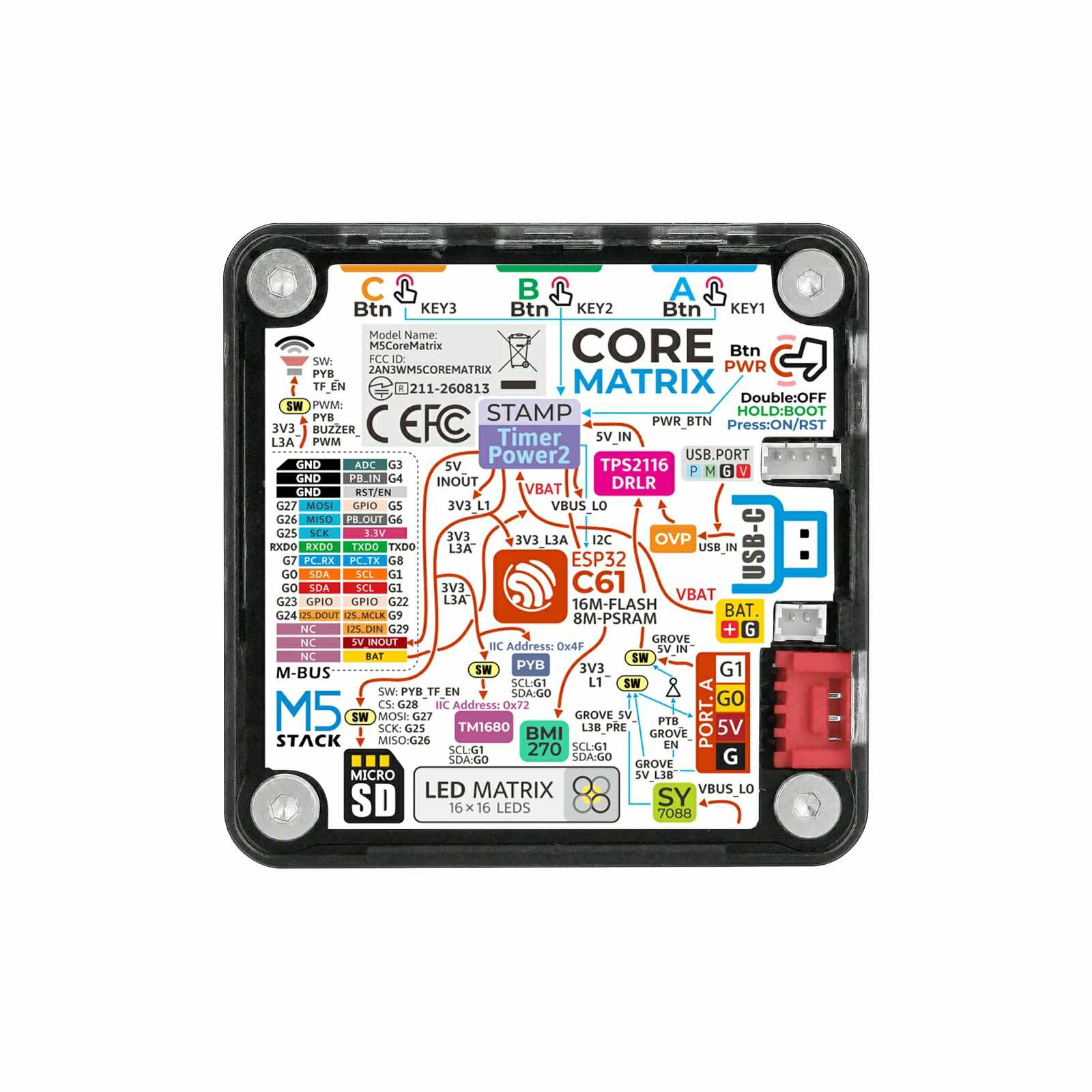
PinMap
LED Matrix
| ESP32-C61HR8 | G0 | G1 |
|---|
| TM1680 | SDA | SCL |
The LED matrix power is controlled via PYB_LEDS_EN on the M5IOE1. The 7-bit I2C address of the TM1680 is 0x72; the 0xE4 shown in the schematic is the 8-bit address including the read/write bit.
microSD
| ESP32-C61HR8 | G27 | G26 | G25 | G28 |
|---|
| microSD | MOSI | MISO | SCK | CS |
The microSD card slot power is controlled via PYB_TF_EN on the M5IOE1, and PYB_TFCARD_DET detects whether a microSD card is inserted.
| PYB_TFCARD_DET | Status |
|---|
| LOW | Inserted |
| High Impedance | Not Inserted |
I2C Devices
| ESP32-C61HR8 | G0 | G1 |
|---|
| BMI270 (0x68) | SDA | SCL |
| TM1680 (0x72) | SDA | SCL |
| M5IOE1 (0x4F) | SDA | SCL |
| Stamp Timer Power2 (M5PM1) (0x6E) | SDA | SCL |
USB.PORT
| ESP32-C61HR8 | G12 | G13 | GND | 5V |
|---|
| USB.PORT | USB_D-/USB_DM | USB_D+/USB_DP | GND | 5V |
HY2.0-4P
| HY2.0-4P | Black | Red | Yellow | White |
|---|
| PORT.A | GND | 5V | G0 | G1 |
The Grove 5V output is controlled via PYB_GROVE_EN.
M5-Bus
| FUNC | PIN | LEFT | RIGHT | PIN | FUNC |
|---|
| GND | 1 | 2 | G3 | ADC |
| GND | 3 | 4 | G4 | ADC |
| GND | 5 | 6 | ESP_EN | EN |
| MOSI | G27 | 7 | 8 | G5 | DAC |
| MISO | G26 | 9 | 10 | G6 | DAC |
| SCK | G25 | 11 | 12 | M5BUS_3V3_L0 | |
| RXD0 | G10 | 13 | 14 | G11 | TXD0 |
| RXD2 | G7 | 15 | 16 | G8 | TXD2 |
| SDA | G0 | 17 | 18 | G1 | SCL |
| SDA | G0 | 19 | 20 | G1 | SCL |
| GPIO | G23 | 21 | 22 | G22 | GPIO |
| GPIO | G24 | 23 | 24 | G9 | BOOT |
| NC | 25 | 26 | G29 | GPIO |
| NC | 27 | 28 | 5V_INOUT | |
| NC | 29 | 30 | BAT | |
Stamp Timer Power2 (M5PM1)
| Stamp Timer Power2 (M5PM1) | G0 | G1 | G2 | G3 | G4 |
|---|
| KEY | KEY1 (BtnA) | KEY2 (BtnB) | KEY3 (BtnC) | | |
| ESP32-C61HR8 | | | | ESP_G2_IRQ | |
| IMU | | | | | PYG4_IMU_INT |
- G0(KEY1): BtnA button input
- G1(KEY2): BtnB button input
- G2(KEY3): BtnC button input
- G3(ESP_G2_IRQ): Stamp Timer Power2 (M5PM1) interrupt signal output
- G4(PYG4_IMU_INT): BMI270 interrupt wake-up signal
M5IOE1
| M5IOE1 | IO1 | IO2 | IO3 | IO4 | IO5 | IO8 | IO10 | IO11 |
|---|
| microSD | PYB_TF_EN | | | | | | PYB_TFCARD_DET | |
| Buzzer | | PYB_BUZZER_EN | | | | | | PYB_BUZZER_PWM |
| Charge | | | PYB_CHG_PROG | | | PYB_CHG_STAT | | |
| LED Matrix | | | | PYB_LEDS_EN | | | | |
| Grove | | | | | PYB_GROVE_EN | | | |
- IO1(PYB_TF_EN): microSD card slot power enable
- IO2(PYB_BUZZER_EN): Buzzer power enable
- IO3(PYB_CHG_PROG): Charging current control
- IO4(PYB_LEDS_EN): LED matrix power enable
- IO5(PYB_GROVE_EN): Grove 5V output enable
- IO8(PYB_CHG_STAT): Charging status detection; low level indicates charging
- IO10(PYB_TFCARD_DET): microSD card insertion status detection
- IO11(PYB_BUZZER_PWM): Buzzer PWM drive
| PYB_CHG_PROG | CHARGE CURRENT |
|---|
| LOW | 650mA |
| HIGH | 180mA (Default) |
Model Size
Structure
Datasheets
Softwares
Arduino
UiFlow2
Protocol
Video