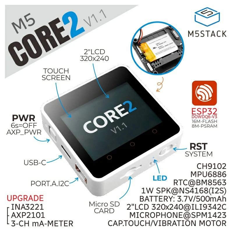
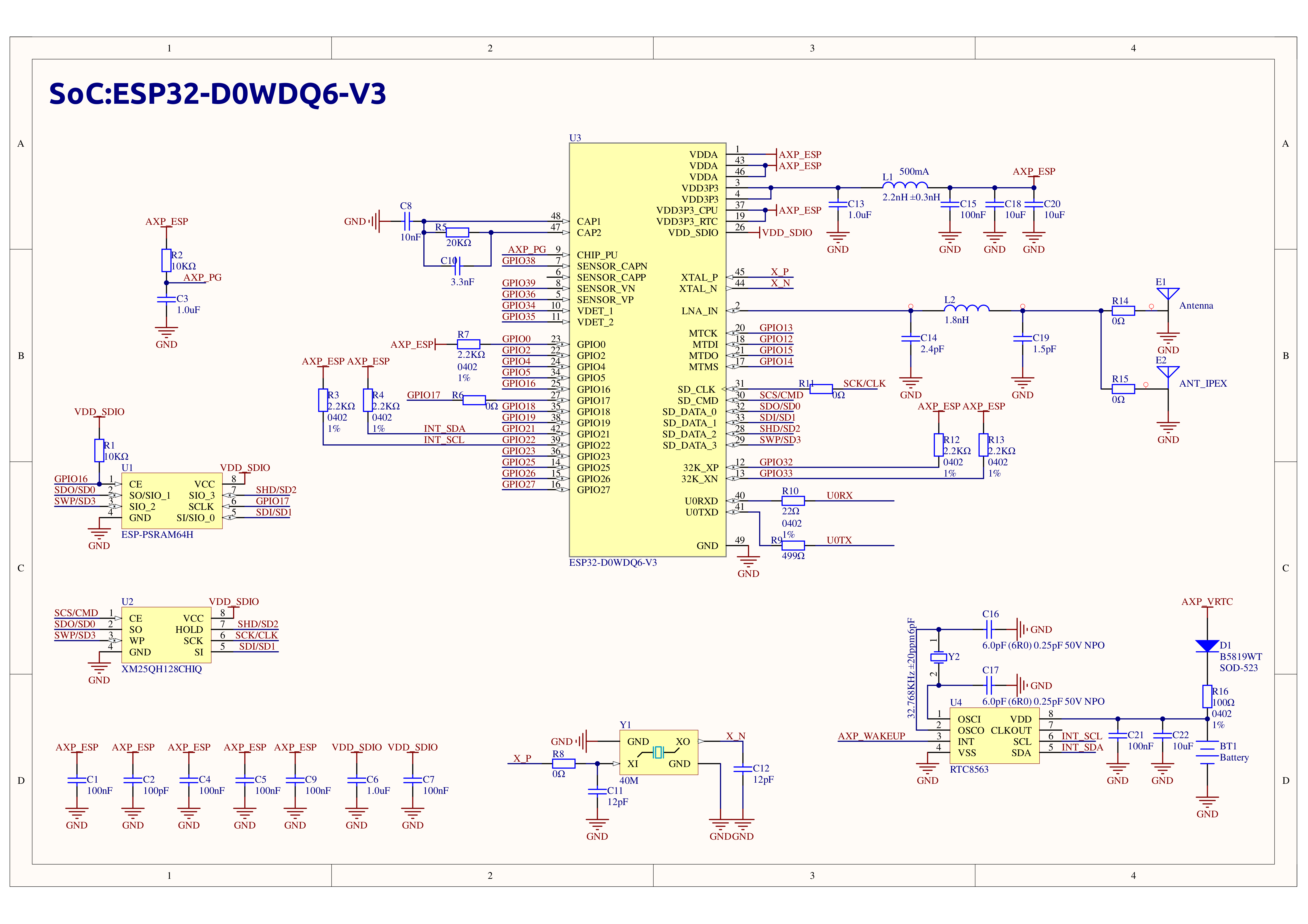
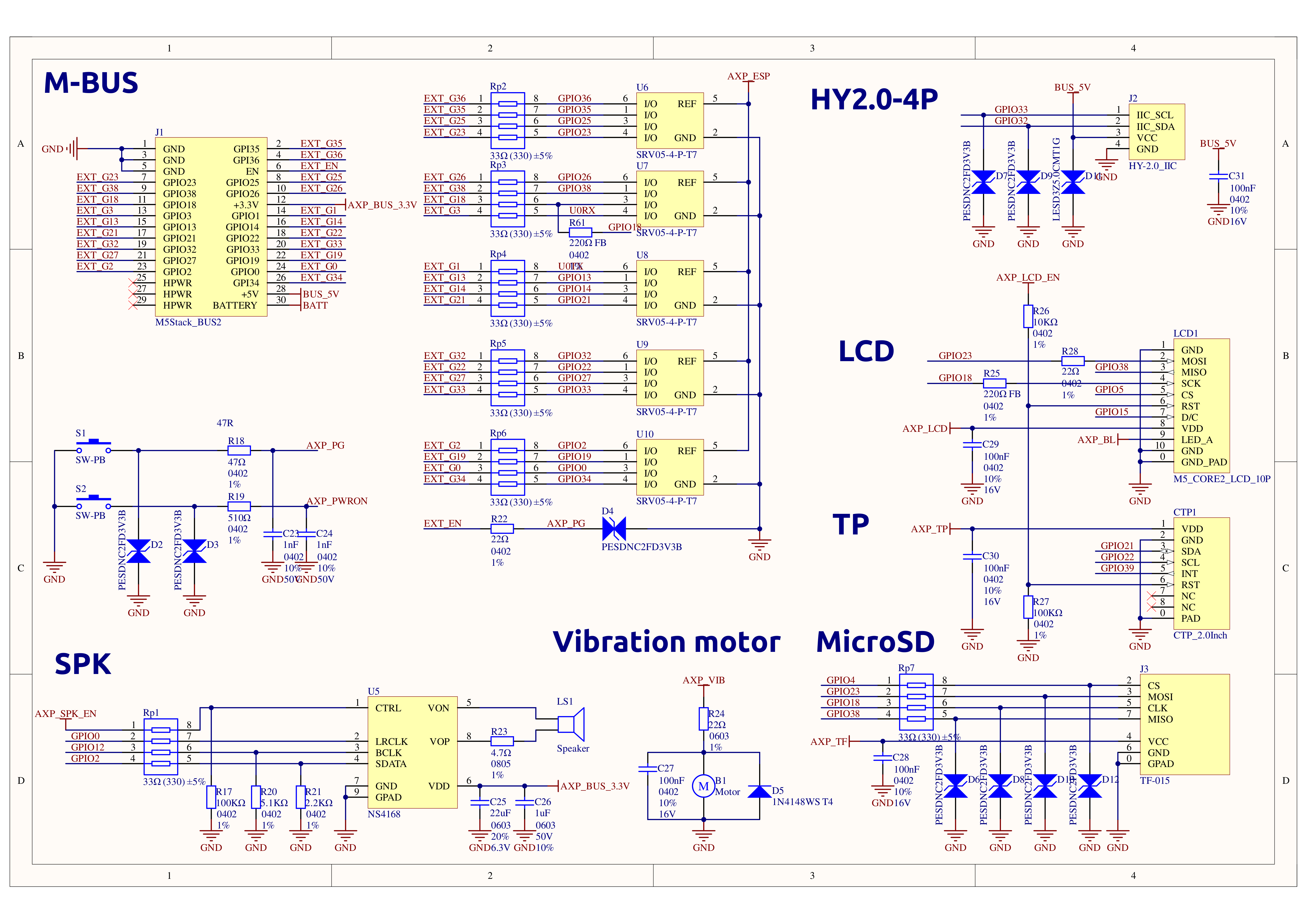
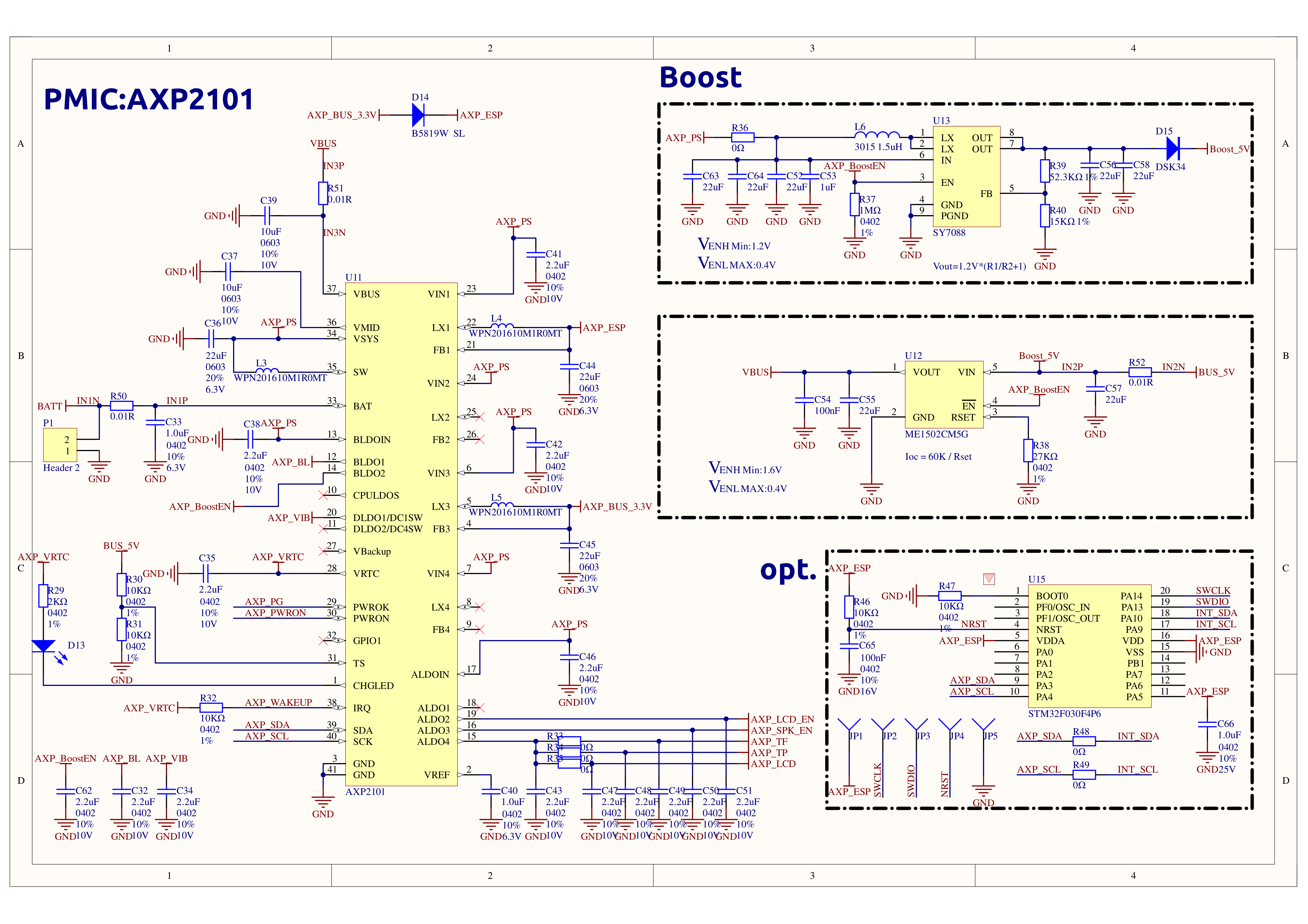
Core2 v1.1 is the iterative version of the second-generation host in the M5Stack development kit series, further enhancing the functionality based on the original generation host. It features a power management chip solution of AXP2101+INA3221, offering more comprehensive hardware functions, adding an RTC battery to meet the needs of low-power applications and precise timing functions. Its core controller is equipped with an ESP32-D0WDQ6-V3, featuring two independently controllable Xtensa® 32-bit LX6 processors, with a main frequency of up to 240MHz, supporting WiFi functionality, and onboard 16MB Flash and 8MB PSRAM. Programs can be downloaded via the TYPE-C interface, and the robust configuration meets the resource demands of complex applications. The front is equipped with a 2.0-inch integrated capacitive touch screen, providing users with a smoother human-computer interaction experience.
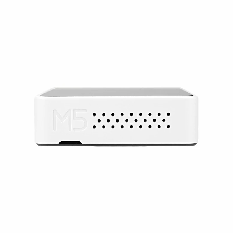
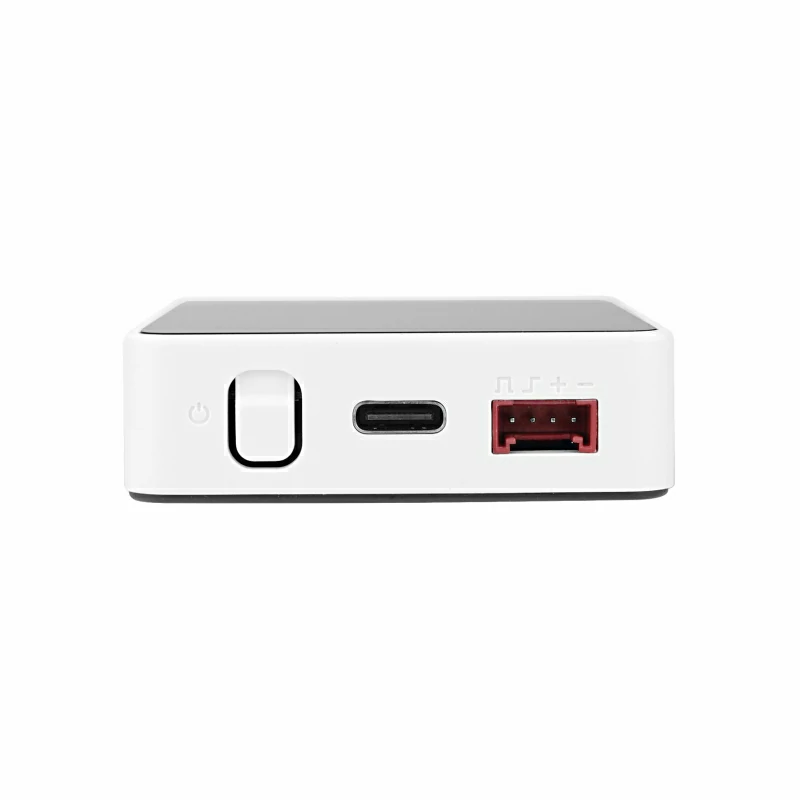
The body has a built-in vibration motor, providing tactile feedback and vibration alert functions. The built-in RTC module and battery dedicated to RTC power supply offer precise timing functions. The power section features an AXP2101 power management chip for effective control of body power consumption, with a built-in blue power indicator light. Additionally, the body is equipped with a TF-card (microSD) slot and speaker. To ensure higher quality sound effects, an I2S digital audio interface amplifier chip is used to effectively prevent signal distortion. The left side and bottom of the body have independent power and reset (RST) buttons, and the three dots on the front of the screen are part of the touch screen, which can be programmed to map hot zones as three virtual buttons. The expansion board on the back of the body integrates a 6-axis IMU sensor and microphone.
This tutorial shows how to program and control the Core2 v1.1 device using the Arduino IDE.
Note
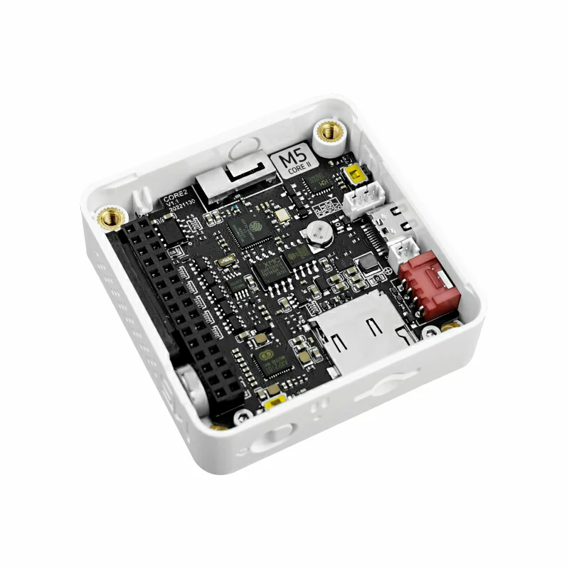
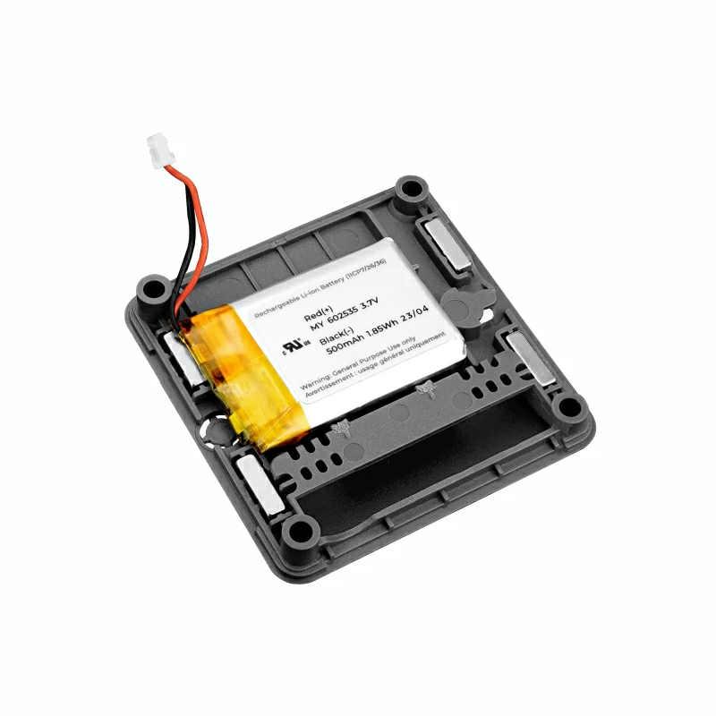
When stacking Core2 V1.1 with M5 modules, you need to remove the battery bottom of Core2 V1.1. If you want to retain the I2S microphone, IMU, and battery functions of the base while stacking other modules, the M5GO Bottom2 is recommended. The PCB of Core2 V1.1 has reserved interfaces for the CH910F chip and a lithium battery connector.
The built-in vibration motor of Core2 V1.1 interferes structurally with the M5 Base series bases. To avoid equipment damage, do not stack Core2 V1.1 with any M5 Base series functional bases.
Some screens may have non-linear touch response at the edges. You can try upgrading the screen firmware using M5Tool to resolve this issue.
Features
Developed based on ESP32, supports Wi-Fi
16MB Flash, 8MB PSRAM
Built-in speaker, power indicator light, vibration motor, RTC, I2S amplifier, capacitive touch screen, power button, reset button
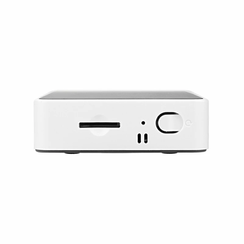
microSD slot
Built-in lithium battery, equipped with a power management chip
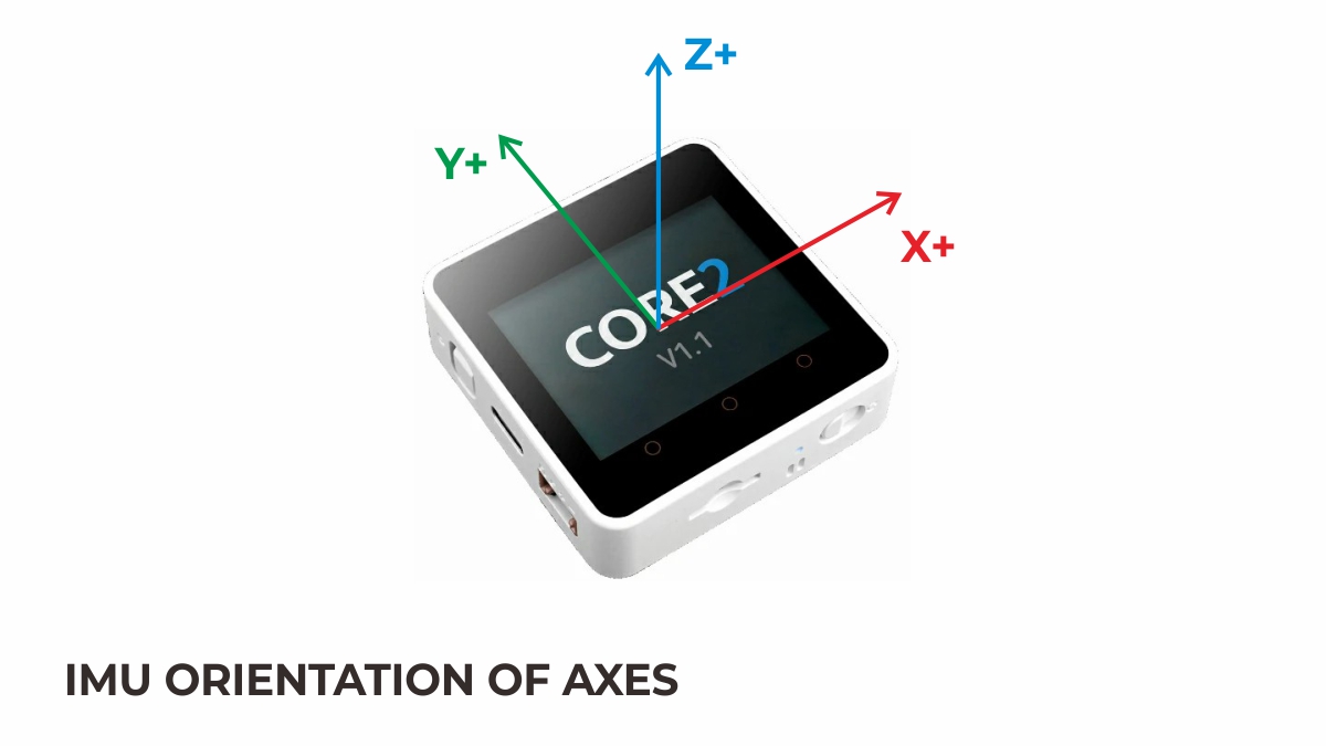
Independent board with built-in 6-axis IMU, PDM microphone
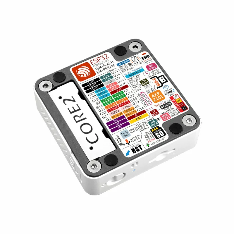
M5-Bus interface
Development Platform
UiFlow1
UiFlow2
Arduino IDE
ESP-IDF
PlatformIO
Includes
1 x Core2 V1.1
1 x USB Type-C Cable (20cm)
1 x Hex Key L-Shape 2.0mm (For M2.5 Screw)
Applications
IoT controller
STEM education
DIY projects
Smart home devices
Specifications
Specification
Parameter
SoC
ESP32-D0WDQ6-V3 @ Dual-core processor, 240MHz main frequency
DMIPS
600
SRAM
520KB
Flash
16MB
PSRAM
8MB
Wi-Fi
2.4 GHz Wi-Fi
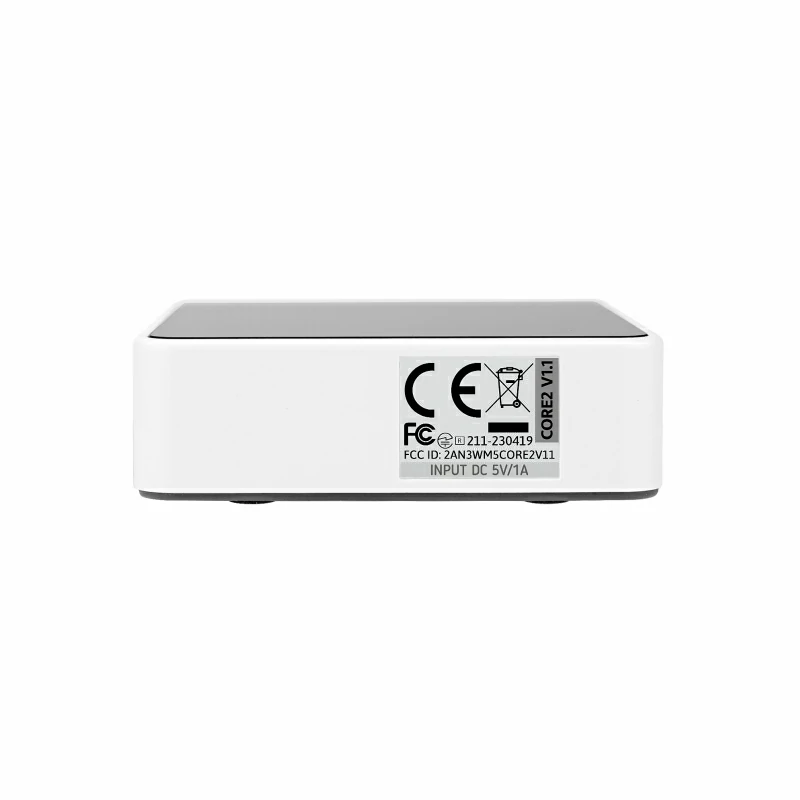
Input Voltage
5V@500mA
Host Interface
USB Type-C x 1, GROVE (I2C+I/O+UART) x 1
LED
Blue power indicator LED
Button
Power button, RST button, screen virtual buttons * 3
Vibration Alert
Vibration motor
IPS LCD Screen
2.0"@320 x 240 ILI9342C
Capacitive Touch IC
FT6336U
Speaker Amplifier
1W (Size: 0928)
Microphone
SPM1423
I2S Amplifier
NS4168
IMU
MPU6886
RTC
BM8563
PMU
AXP2101
Current Meter
INA3221
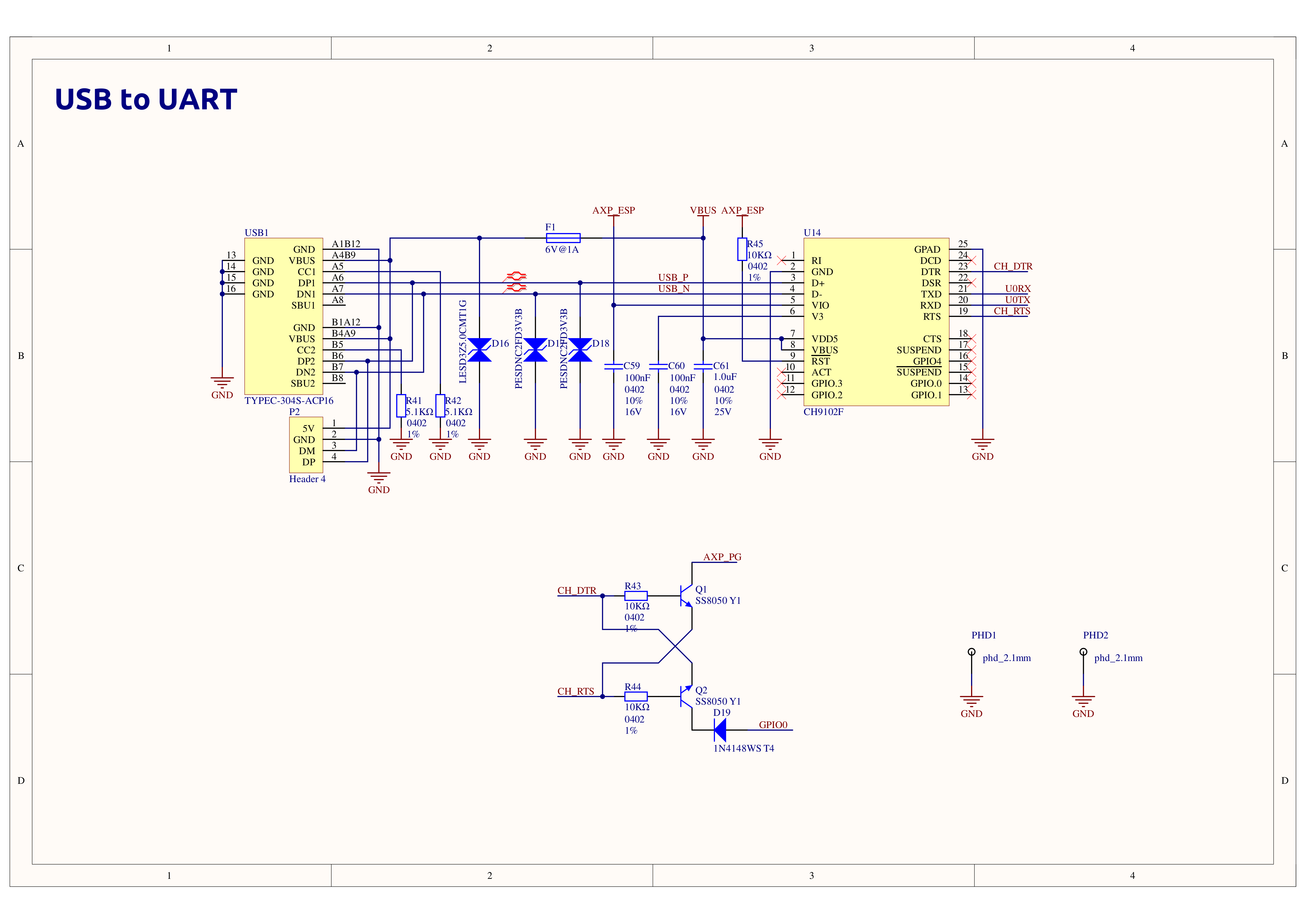
USB Chip
CH9102F
DC-DC Boost
SY7088
Lithium Battery
500mAh @ 3.7V
Antenna
2.4G 3D antenna
Operating Temperature
0 ~ 60°C
Base Screw Spec
Hex socket countersunk head M3
Reserved Internal PCB Ports
Battery port (Spec: 1.25mm-2P) USB cable port (Spec: 1.25mm-4P)
Case Material
Plastic ( PC )
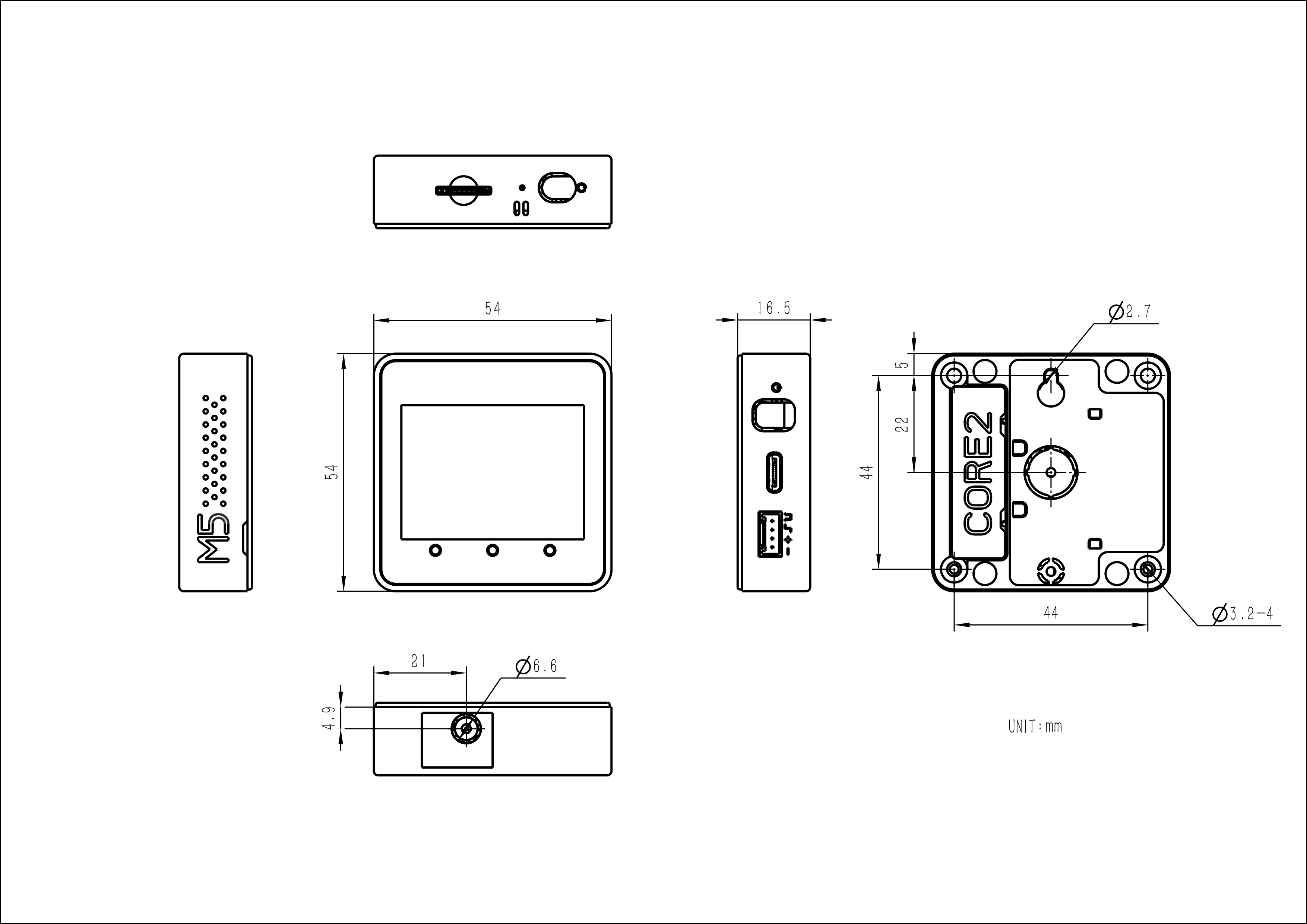
Product Size
54.0 x 54.0 x 16.5mm
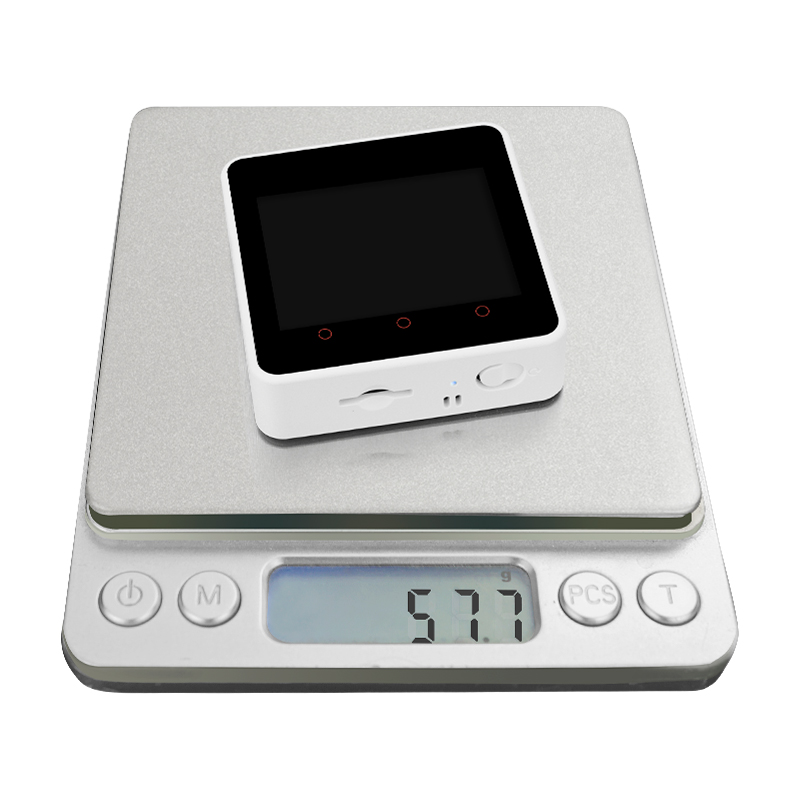
Product Weight
45.1g
Package Size
80.0 x 59.9 x 21.6mm
Gross Weight
74.3g
Learn
Power Management
Power On: Single click the left power button
Power Off: Long press the left power button for 4 seconds
Click the link below to download the driver matching your operating system. There are currently two driver chip versions, CP34X (for CH9102 version) driver package. After extracting the package, select the installation package corresponding to your operating system's bit version for installation. (If you are unsure which USB chip your device uses, you can install both drivers. CH9102_VCP_SER_MacOS v1.7 may report an error during installation, but it is actually installed, just ignore it.) If you encounter issues with downloading programs (timeout or Failed to write to target RAM), try reinstalling the device driver.
This example will perform hardware operation tests for the speaker, Wi-Fi, buttons, accelerometer, microSD, screen, etc.
Product Comparison
To compare information on the controller series products, you can visit the Product Selection Table, check the target products, and get the comparison results. The selection table covers key information such as core parameters and functional features, and supports comparison of multiple products simultaneously.
AXP2101 (Core2 v1.1) vs AXP192 (Core2) Parameter Comparison
Feature
AXP2101 (Core2 v1.1)
AXP192 (Core2)
Battery Voltage
0.7V ~ 4.2V
0.7V ~ 4.2V
Battery Charging Current
100mA
500mA
Battery Charging Efficiency
94%
90%
Battery Charging Termination Current
10mA
50mA
Battery Discharge Efficiency
96%
95%
Power Output Current
300mA
500mA
Power Output Efficiency
95%
90%
Core2 vs Core2 v1.1 Differences
Comparison Item
Core2
Core2 v1.1
Power Management Solution
AXP192 chip only
AXP2101 + INA3221 combined solution
Power Indicator Color
Green
Blue
RTC Timing Function
No independent backup battery, inaccurate after power-off
Equipped with RTC chip backup battery, accurate timing after power-off
AXP192 and AXP2101 have different IDs, which the program uses as a flag to distinguish versions.
Version Change
Release Date
Product Changes
Note
2023.11
Core2 v1.1
Changed PMU power management chip to AXP2101+INA3221, added RTC backup battery, and changed the power indicator to blue
/
First release Core2
/
Version Comparison
The differences between Core2 and Core2 v1.1 are as follows: 1. The power management solution has been iterated from Core2 (AXP192) to Core2 v1.1 (AXP2101+INA3221), with different IDs for AXP192 and AXP2101, used as a version distinction marker in programs, 2. The power indicator light has changed from green to blue; 3. Added an RTC chip power supply battery to ensure precise timing even when powered off.