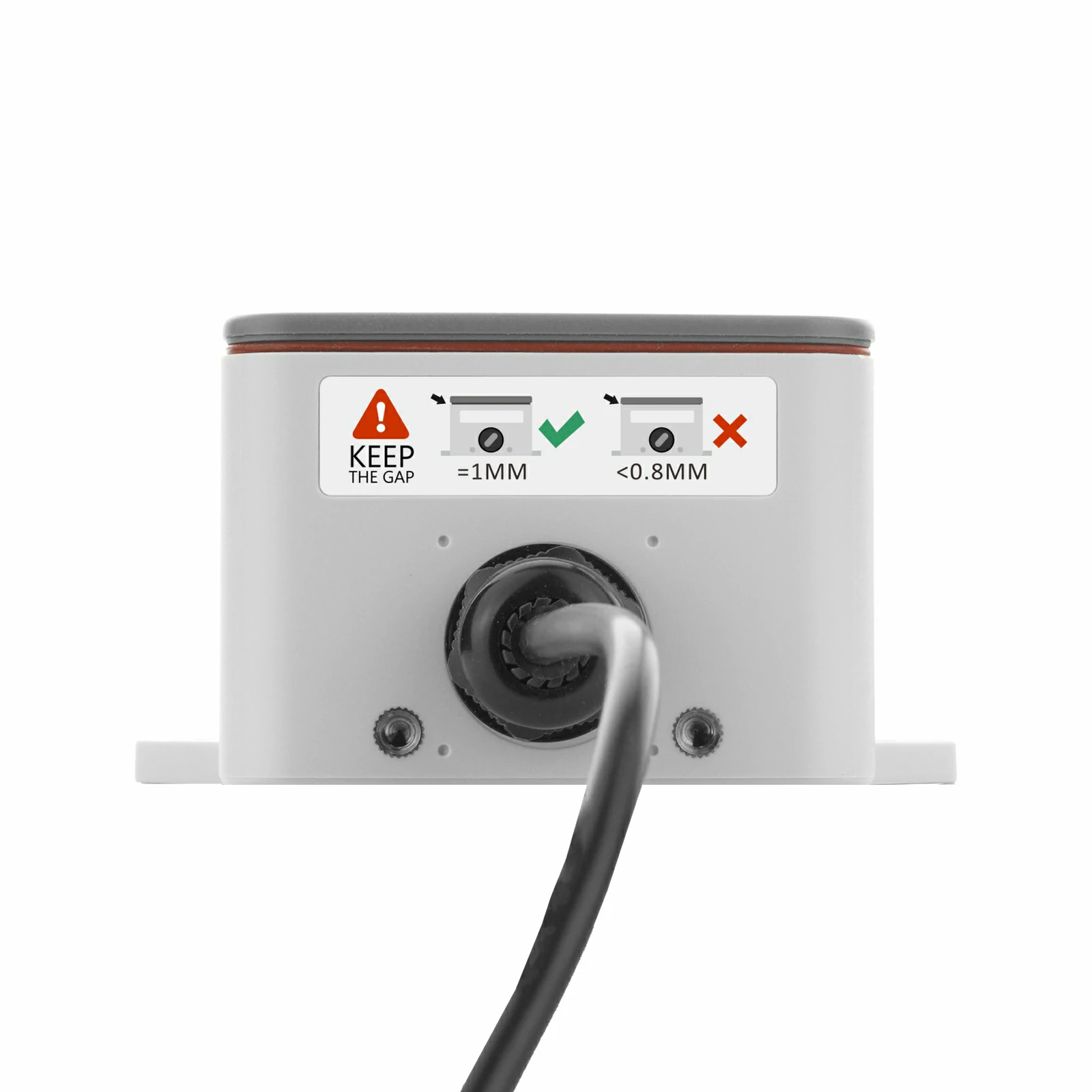
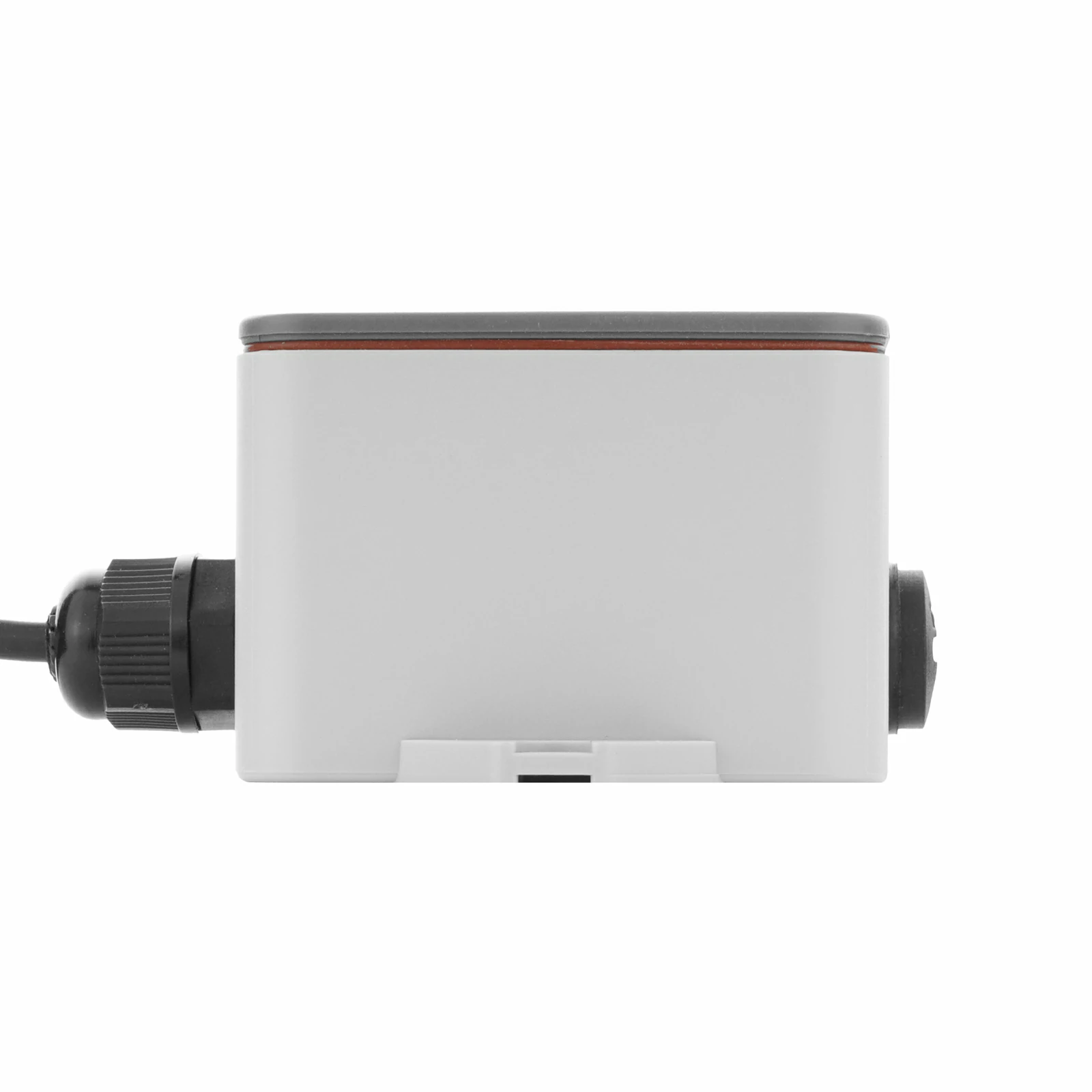
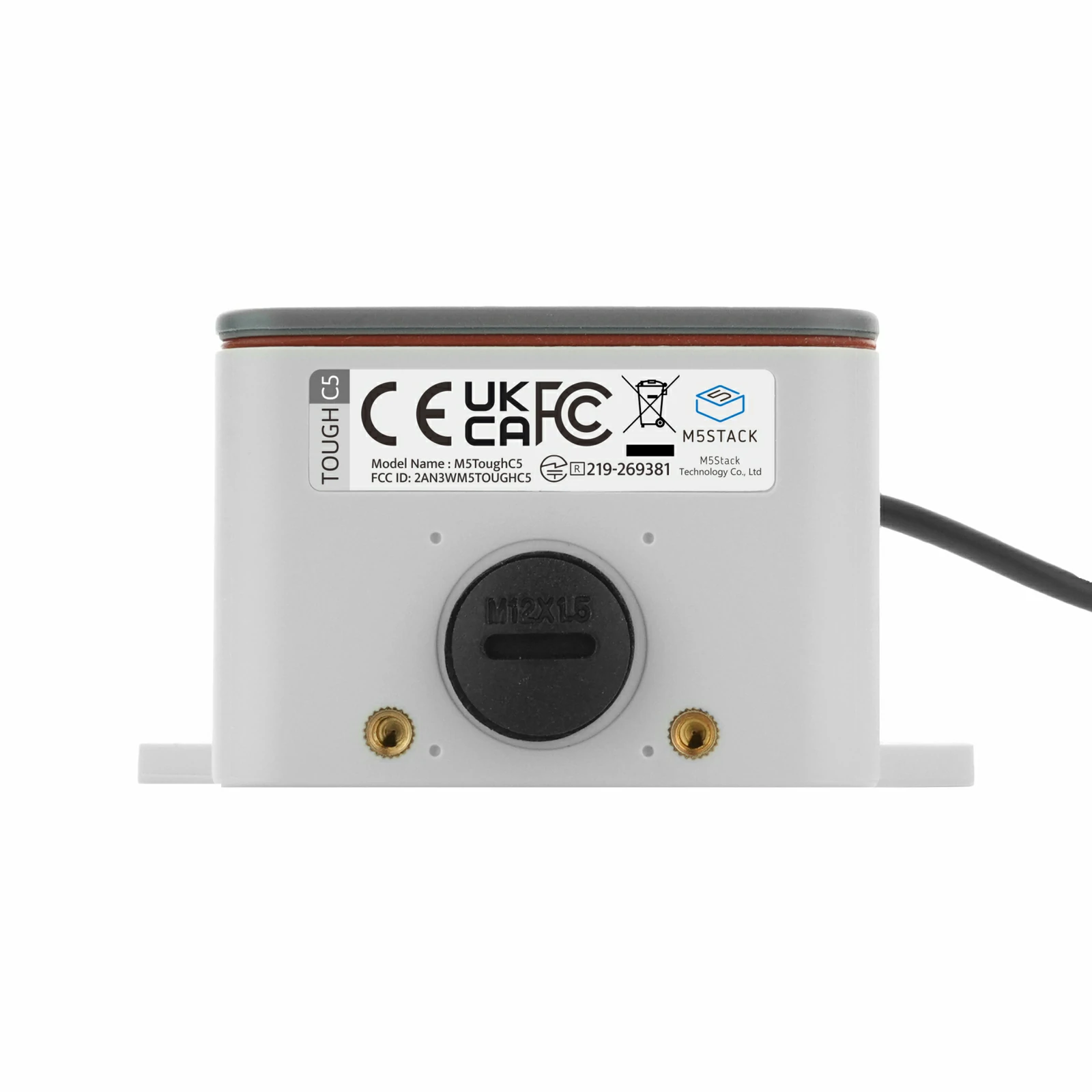
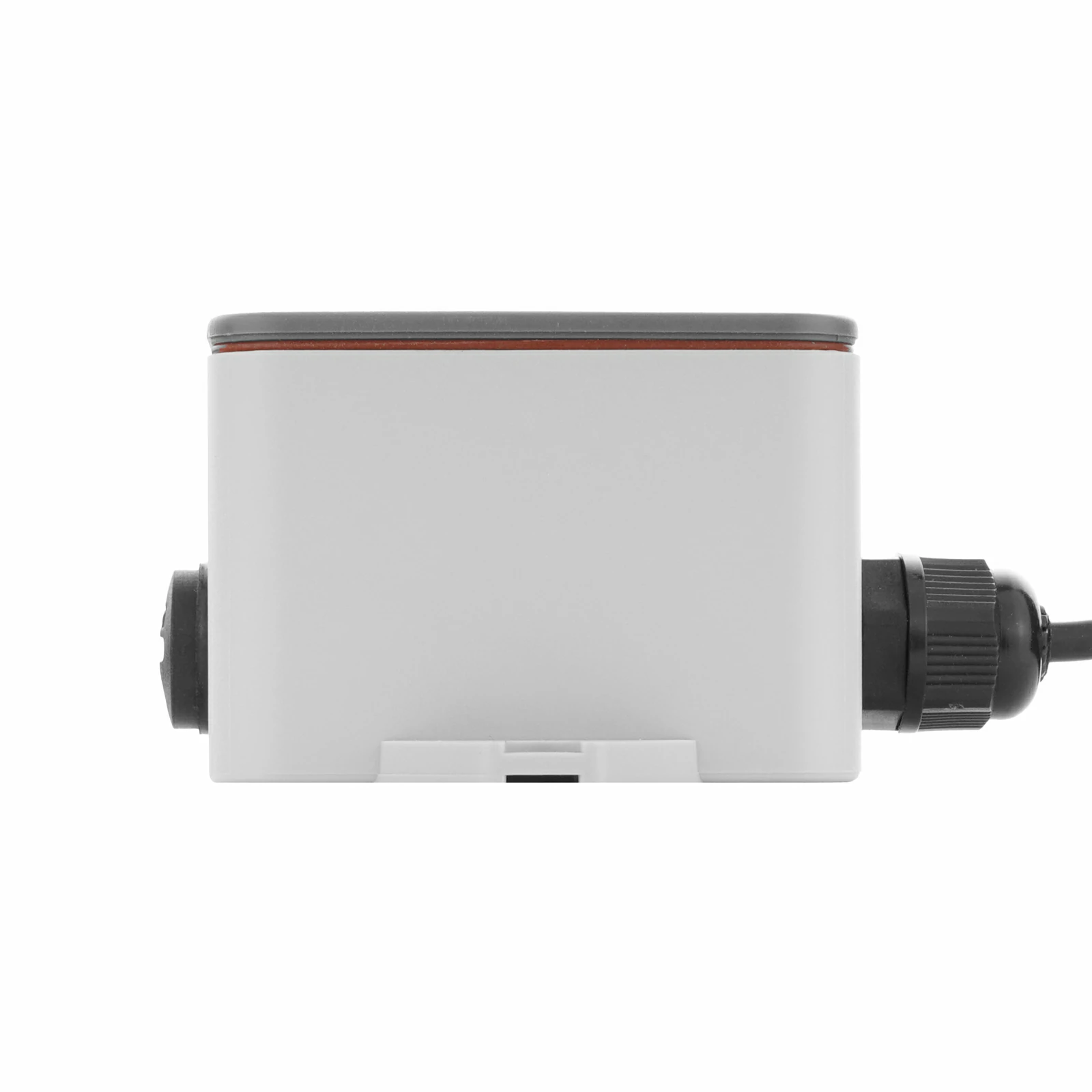
ToughC5
SKU:K162
Description
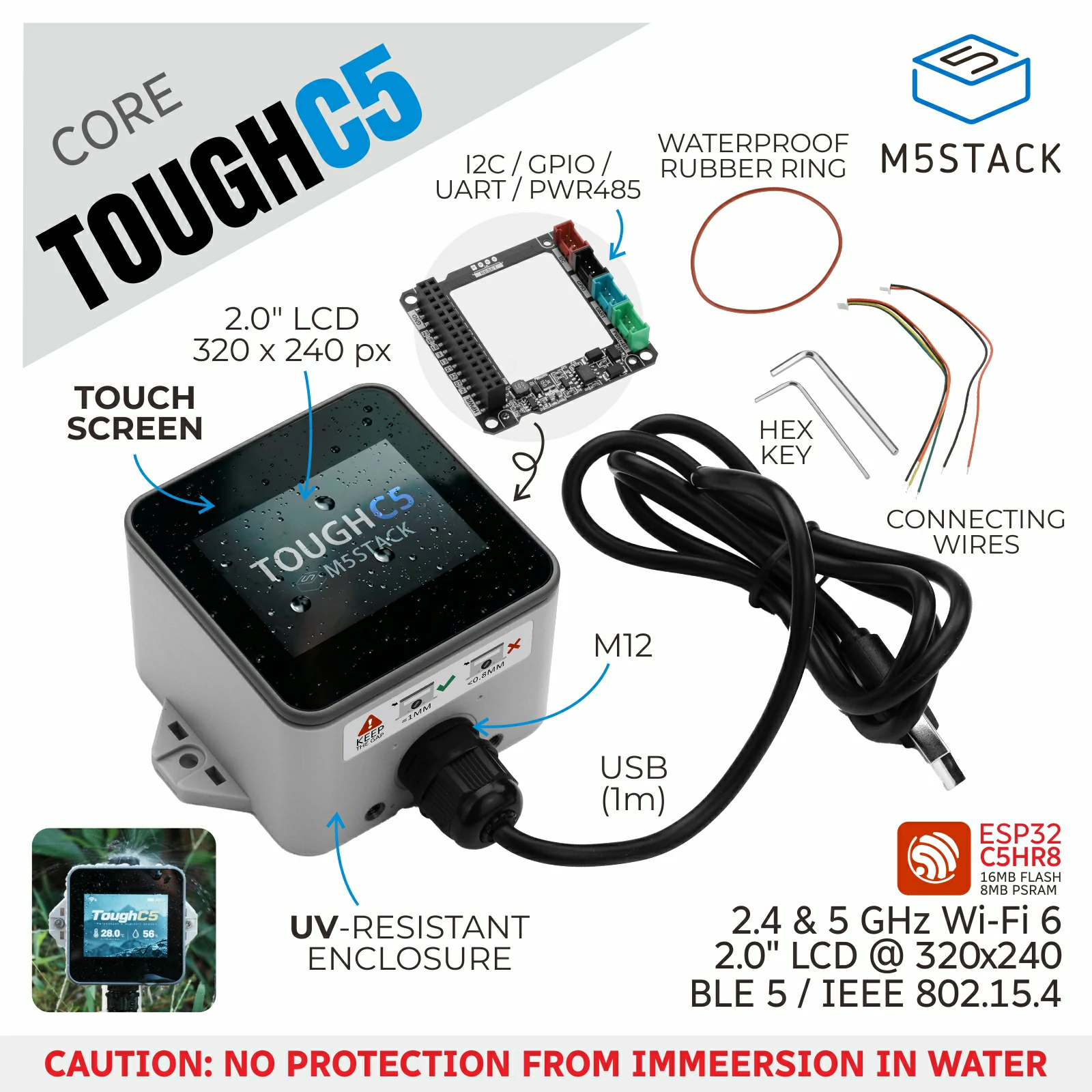
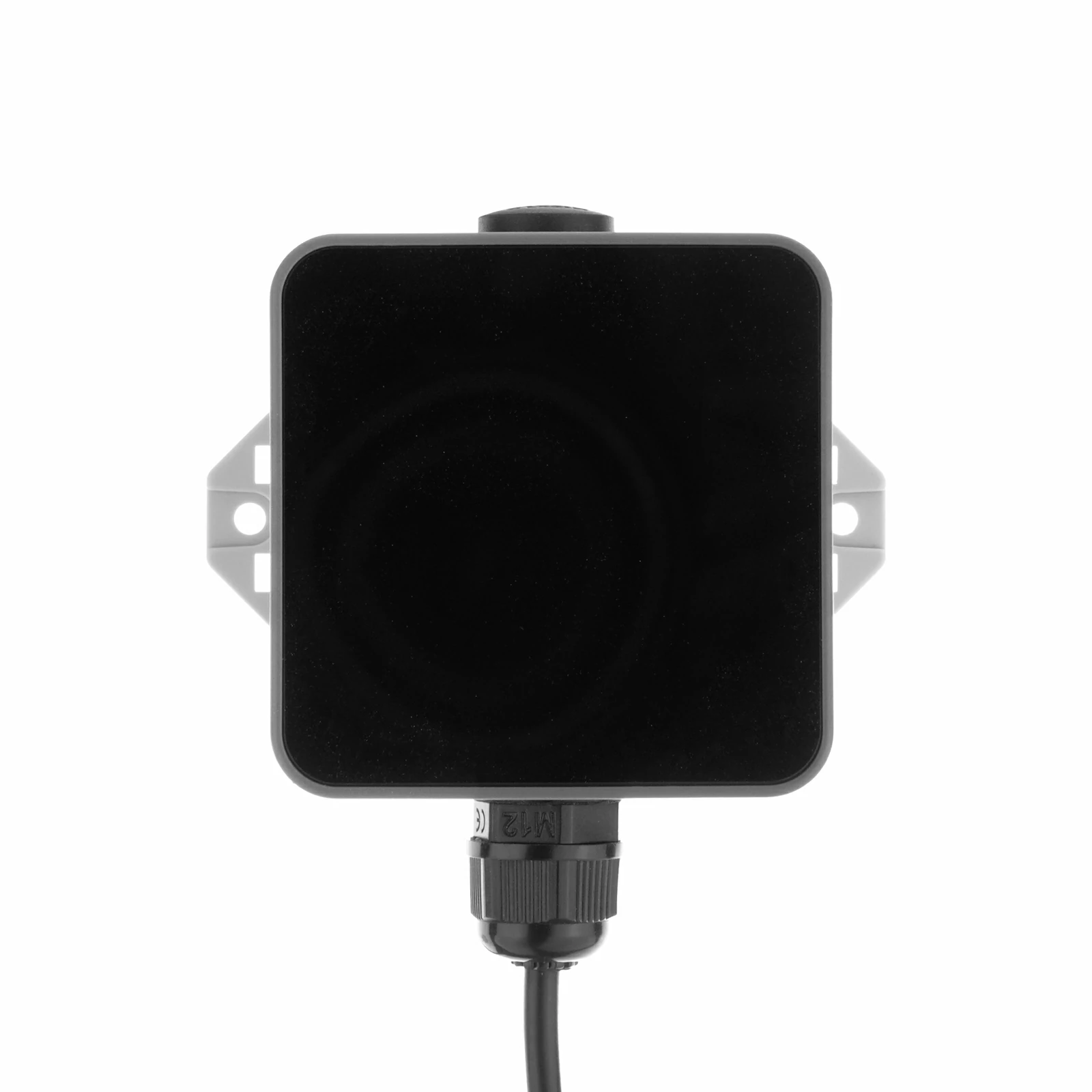
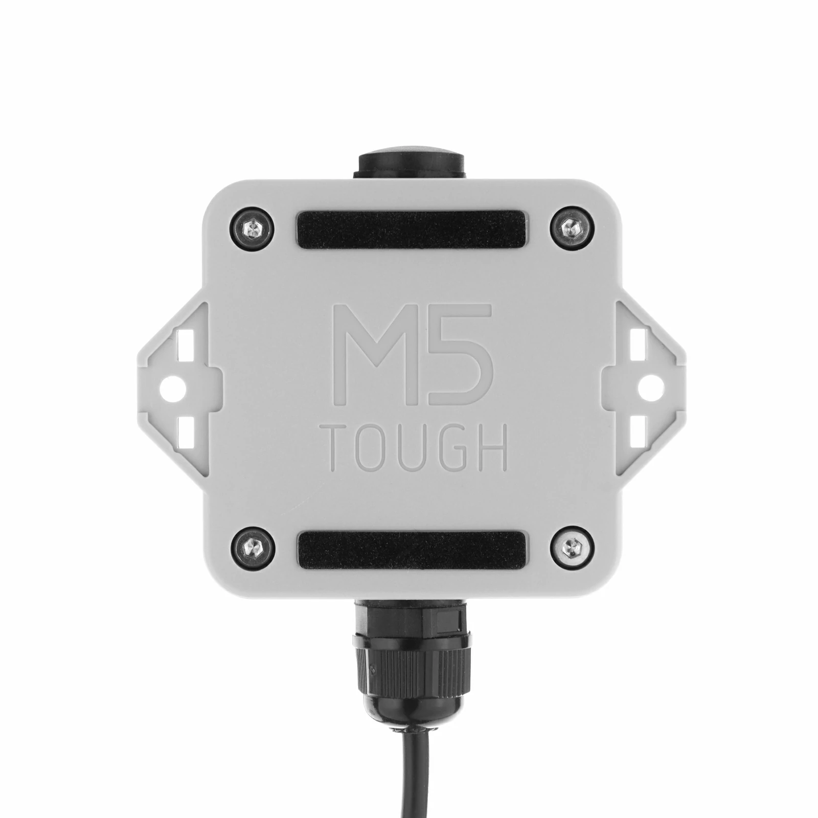
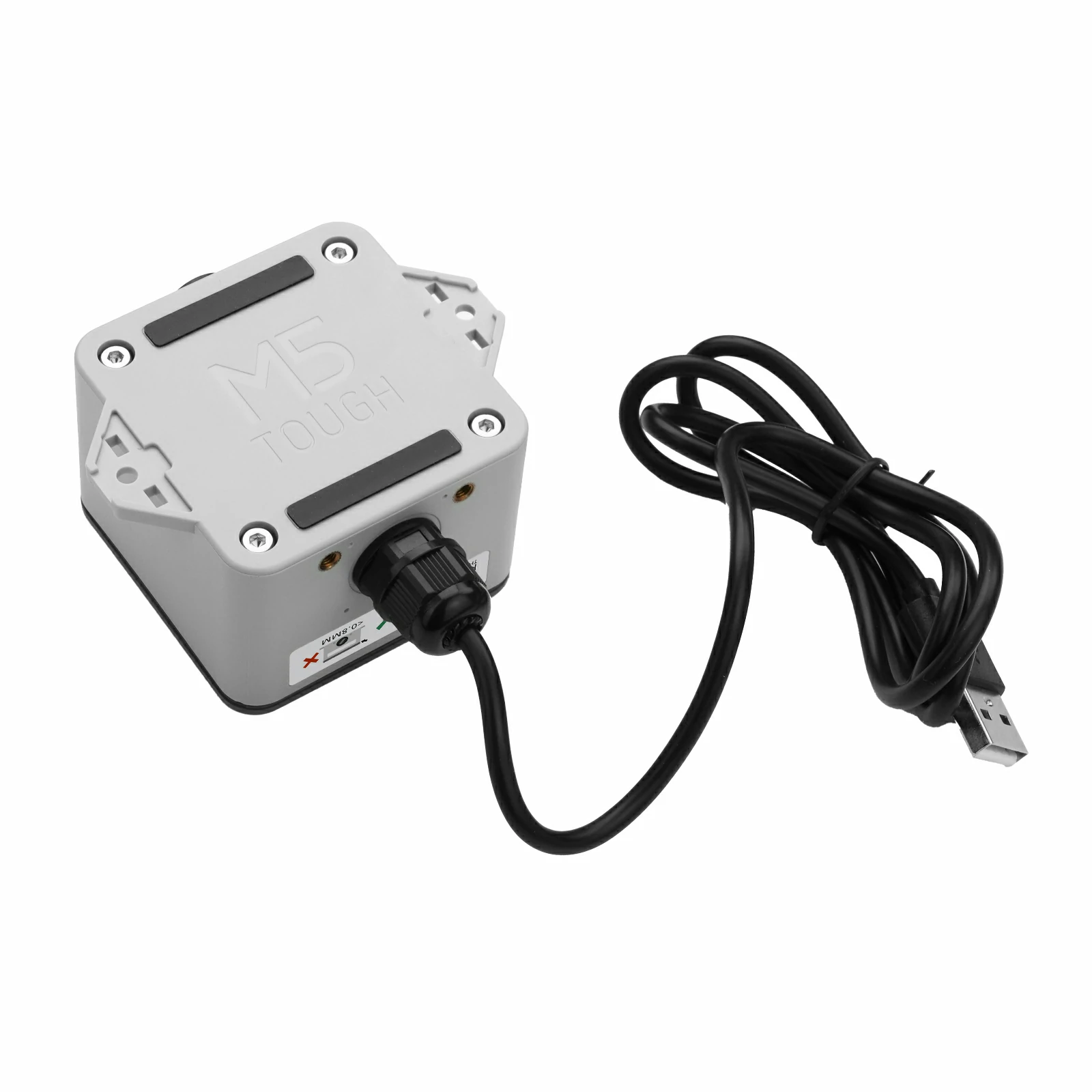
ToughC5 is an outdoor waterproof IoT controller. Built around the ESP32-C5HR8 core module, it features a RISC-V 32-bit single-core processor running at 240MHz, with 16MB Flash and 8MB PSRAM. It supports 2.4 & 5 GHz dual-band Wi-Fi 6, BLE 5, and IEEE 802.15.4 (Zigbee, Thread) multi-protocol connectivity, meeting access requirements across a variety of network scenarios.
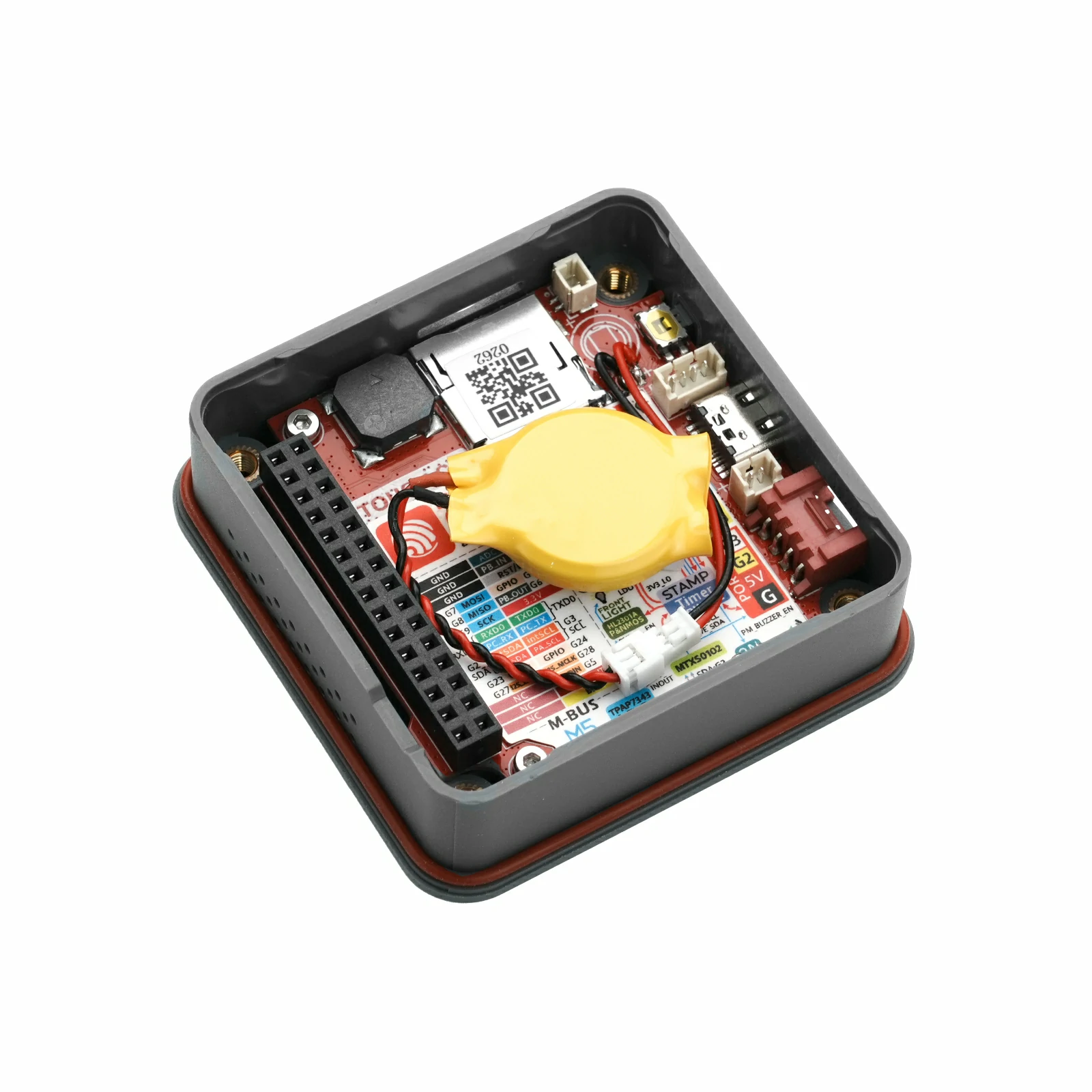
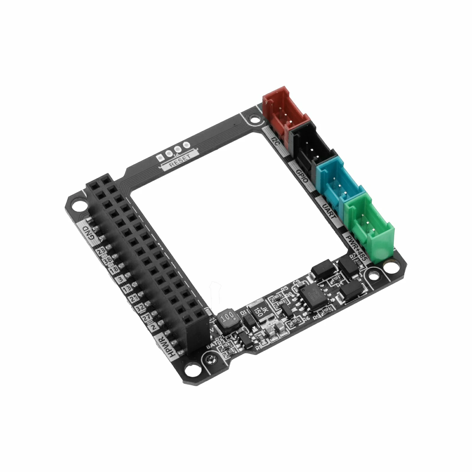
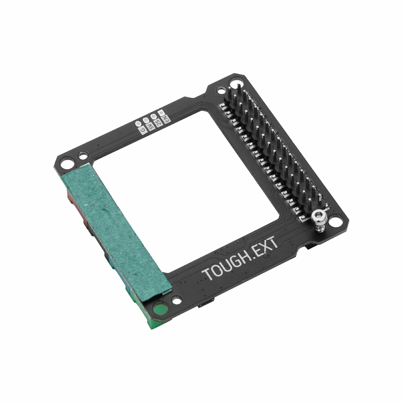
It integrates a 2.0" color LCD display (resolution 320 × 240) with a highly sensitive capacitive touch panel, and includes an onboard buzzer, microSD card slot, and RX8130CE real-time clock. The housing is made of PC + ABS (with UV powder), providing resistance to UV aging. Internally, the device offers I2C, GPIO, UART, and RS485 expansion interfaces as well as a battery connector, which are routed externally through the M12 connectors on both sides of the body for additional expansion. The system uses M5PM1 + M5IOE1 for multi-level power management and supports low-power wake-up. The device provides standard water and dust resistance (not designed for immersion), making it suitable for a wide range of applications such as outdoor edge data collection, smart buildings, and industrial gateways.
Tutorial
This tutorial will introduce how to program and control the ToughC5 device via Arduino IDE.
Features
- ESP32-C5HR8 Core Main Controller
- 16MB Flash
- 8MB PSRAM
- 2.4 & 5 GHz Dual-Band Wi-Fi 6
- Supports BLE 5 / IEEE 802.15.4 (Zigbee, Thread)
- Human-Machine Interaction
- 2.0" LCD Capacitive Touch Screen, 320 x 240 Resolution
- Onboard Passive Buzzer
- Clock and Power
- Onboard RX8130CE RTC Clock
- RTC Clock Battery (CR2032 Coin Cell Battery DC 3V@220mAh)
- M5PM1 + M5IOE1 Multi-Level Power Management
- DC 3.7V Battery Interface
- Interfaces and Expansion
- USB Type-C for Debugging / Program Download
- Internal Interface Expansion Board: HY2.0-4P x 4 (RS485/I2C/GPIO/UART)
- 2x M12 Body Cable Routing Holes
- microSD Card Slot
- Easy Wiring, Magnetic Mounting
- PC + ABS (with UV Powder) Housing Material, Resistant to UV Aging
Includes
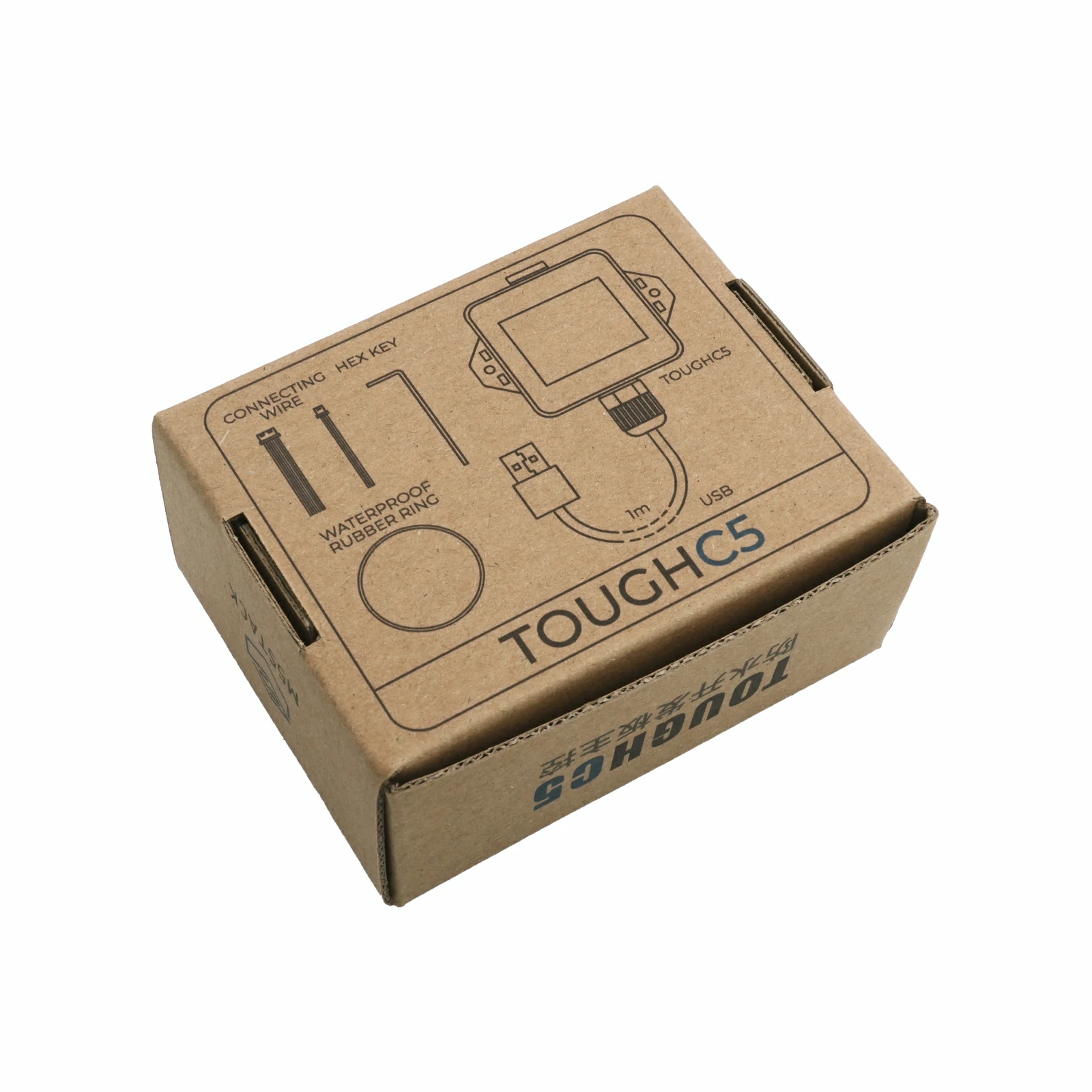
- 1 x ToughC5
- 1 x USB Type-C Cable (1m)
- 1 x Hex Key L-Shape 2.5mm (For M3 Screw)
- 1 x Hex Key L-Shape 1.5mm (For M2 Screw)
- 1 x 1.25-2P Single-Head Terminal Cable
- 1 x 1.25-4P Single-Head Terminal Cable
- 1 x Waterproof O-Ring
Applications
- Outdoor edge data collection
- Outdoor industrial field control
- Outdoor environment gateway monitoring
- Field low-power sensor terminals
Specifications
| Specification | Parameter |
|---|
| SoC | ESP32-C5HR8 @ RISC-V® 32-bit single-core processor, up to 240MHz |
| Flash | 16MB |
| PSRAM | 8MB Quad |
| Wireless Connectivity | 2.4 & 5 GHz dual-band Wi-Fi 6 / BLE 5 / IEEE 802.15.4 (Zigbee, Thread) |
| Input Voltage | USB (DC 5V@500mA) / RS485 interface input power (DC 6 ~ 24V@1A) / Battery (DC 3.7V) |
| Interface | USB Type-C x 1, HY2.0-4P x 4 (RS485/I2C/GPIO/UART) |
| RS485 Signal Conversion | RS485 @ SP485EEN-L/TR |
| LCD Screen | 2.0" @ 320 x 240 ILI9342C IPS panel, maximum brightness 853nit |
| Touch Panel Driver IC | CHSC6540 |
| RTC | RTC Chip: RX8130CE
RTC Battery Spec: DC 3V@220mAh, Size 20 x 3.2mm
Battery Socket Spec: SH1.0-2P |
| Battery Connector Spec | MX1.25-2P |
| Buzzer | Onboard passive buzzer @8530 |
| FPC Antenna | 2.4 GHz & 5 GHz, IPEX‑2nd Gen, 14.3x5.3mm, cable length 50mm |
| Power Management | M5PM1 + M5IOE1 |
| Power Consumption | Shutdown state: DC 4.2V@10.41uA
Full load state: DC 4.2V@320mA |
| Housing Material | PC + ABS (with UV powder) |
| Product Size | 75.9 x 58.0 x 42.5mm |
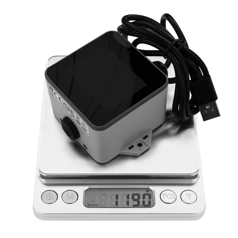
| Product Weight | 119.0g |
| Package Size | 101.0 x 83.0 x 46.0mm |
| Gross Weight | 161.4g |
Learn
Enter Download Mode
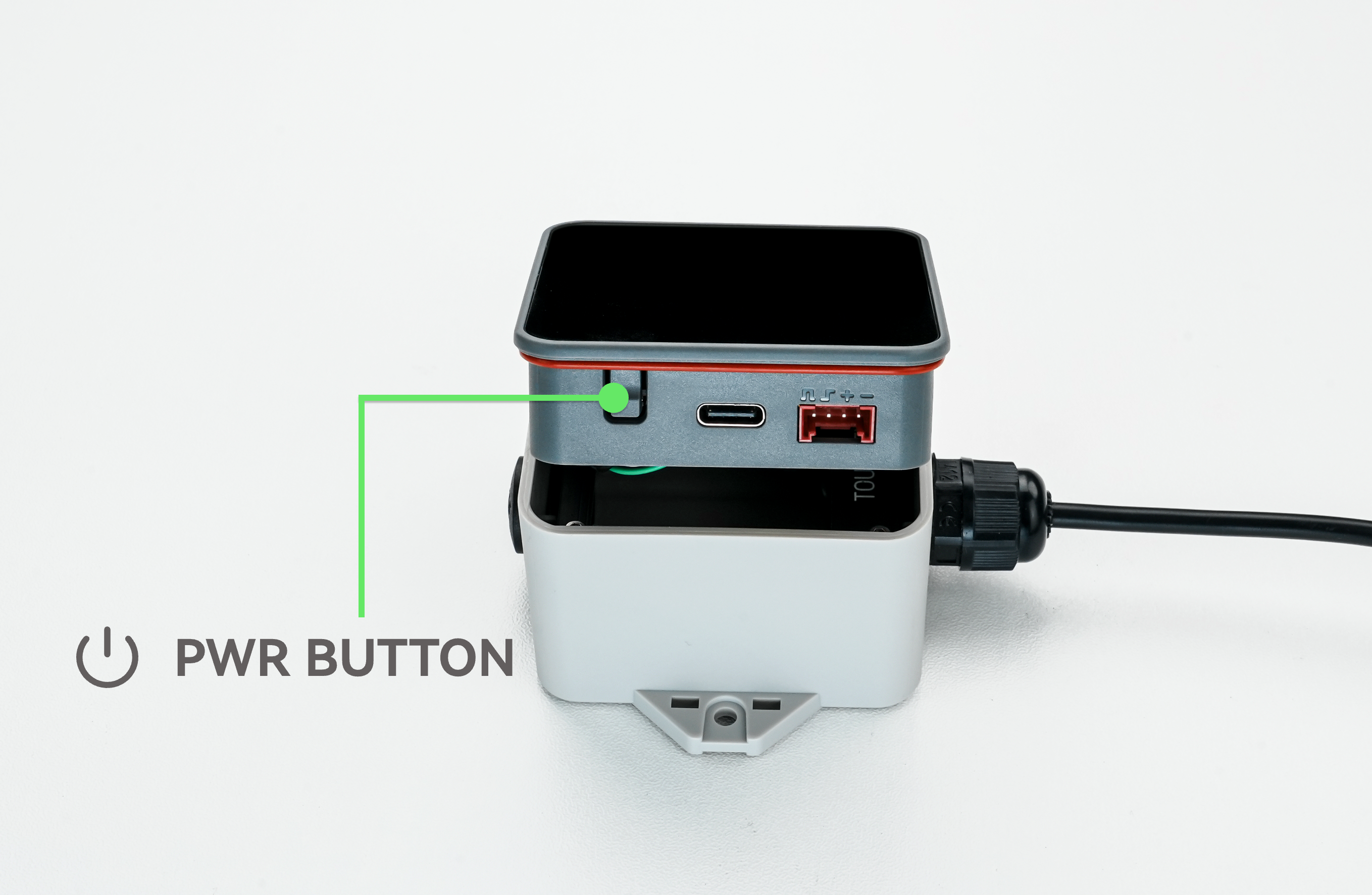
Under normal circumstances, the device can be flashed with programs directly via the USB cable. During development and debugging, if an abnormal program flash occurs, the housing can be removed and the power button long-pressed to force entry into download mode.
- Single click: Power on / Reset
- Double click: Power off
- Long press: Enter download mode




Schematics
PinMap
LCD
| ESP32-C5HR8 | G25 | G26 | G7 | G8 | G9 |
|---|
| ILI9342C | CS | DC | MOSI | MISO | SCK |
The screen enable is controlled via PYG5 (PYB_LCD_EN) of the M5IOE1 expansion chip, and the screen reset is controlled via PYG4 (PYB_LCD_RST).
microSD
| ESP32-C5HR8 | G7 | G8 | G9 | G10 |
|---|
| microSD | MOSI | MISO | SCK | CS |
The microSD card slot enable is controlled via PYG6 (PYB_TF_EN) of the M5IOE1 expansion chip, and PYG14 (PYB_TF_DET) detects the microSD card insertion status.
| PYG14_PYB_TF_DET | Status |
|---|
| LOW | Inserted |
| HIGH | Not Inserted |
Touch
| ESP32-C5HR8 | G2 | G3 |
|---|
| CHSC6540 | SDA | SCL |
The touch screen interrupt signal input is captured via PMG0 (PM_TP_INT) of the M5PM1 power management chip, and PYG2 (PM_TP_RST) controls the touch driver chip reset.
I2C Devices (TP & M5IOE1 & M5PM1)
| ESP32-C5HR8 | G2 | G3 |
|---|
| CHSC6540 (0x2E) | SDA | SCL |
| M5IOE1 (0x4F) | SDA | SCL |
| M5PM1 (0x6E) | SDA | SCL |
RS485
| ESP32-C5HR8 | G23 | G24 |
|---|
| SP485EEN-L/TR | RS485_RX | RS485_TX |
HY2.0-4P
| HY2.0-4P | Black | Red | Yellow | White |
|---|
| PORT.A | GND | 5V | G2 | G3 |
| PORT.B | GND | 5V | G6 | G1 |
| PORT.C | GND | 5V | G12 | G11 |
| PORT.RS485 | GND | DC 6 ~ 24V INPUT | A | B |
M5-Bus
| FUNC | PIN | LEFT | RIGHT | PIN | FUNC |
|---|
| GND | 1 | 2 | G0 | ADC |
| GND | 3 | 4 | G1 | ADC |
| GND | 5 | 6 | RST | EN |
| MOSI | G7 | 7 | 8 | G4 | DAC |
| MISO | G8 | 9 | 10 | G6 | DAC |
| SCK | G9 | 11 | 12 | 3V3 | |
| RXD0 | G12_PC_RX | 13 | 14 | G11_PC_TX | TXD0 |
| RXD2 | G12_PC_RX | 15 | 16 | G11_PC_TX | TXD2 |
| Int SDA | G2 | 17 | 18 | G3 | Int SCL |
| PORT.A SDA | G2 | 19 | 20 | G3 | PORT.A SCL |
| GPIO | G23 | 21 | 22 | G24 | GPIO |
| GPIO | G27 | 23 | 24 | G28 | GPIO |
| NC | 25 | 26 | G5 | GPIO |
| NC | 27 | 28 | 5V | |
| NC | 29 | 30 | BAT | |
M5PM1
| M5PM1 | PYG0 | PYG1 | PYG2 | PYG3 | PYG4 |
|---|
| TOUCH | PM_TP_INT | | PM_TP_RST | | |
| ESP32-C5HR8 | | PM_G1_IRQout | | | |
| RTC | | | | PM_RTC_INT | |
| BUZZER | | | | | PM_BUZZER_EN |
- PYG0(PM_TP_INT): Touch screen interrupt wake-up signal
- PYG1(PM_G1_IRQout): Interrupt output signal connected to ESP32-C5
- PYG2(PM_TP_RST): Touch screen reset
- PYG3(PM_RTC_INT): RTC interrupt wake-up signal
- PYG4(PM_BUZZER_EN): Buzzer drive signal
M5IOE1
| M5IOE1 | PYG1 | PYG3 | PYG4 | PYG5 | PYG6 | PYG10 | PYG14 |
|---|
| CHARGE | PYB_CHG_PROG | PYB_CHG_STAT | | | | | |
| LCD | | | PYB_LCD_RST | PYB_LCD_EN | | PYB_BL_EN | |
| microSD | | | | | PYB_TF_EN | | PYB_TF_DET |
- PYG1(PYB_CHG_PROG): Charge current control
- PYG3(PYB_CHG_STAT): Charge status detection
- PYG4(PYB_LCD_RST): LCD screen reset
- PYG5(PYB_LCD_EN): LCD screen enable
- PYG10(PYB_BL_EN): LCD screen backlight drive signal
- PYG6(PYB_TF_EN): microSD card slot enable
- PYG14(PYB_TF_DET): microSD card slot insertion status detection
| PYG1_CHG_PROG | CHARGE CURRENT |
|---|
| LOW | 650mA |
| HIGH | 180mA (Default) |
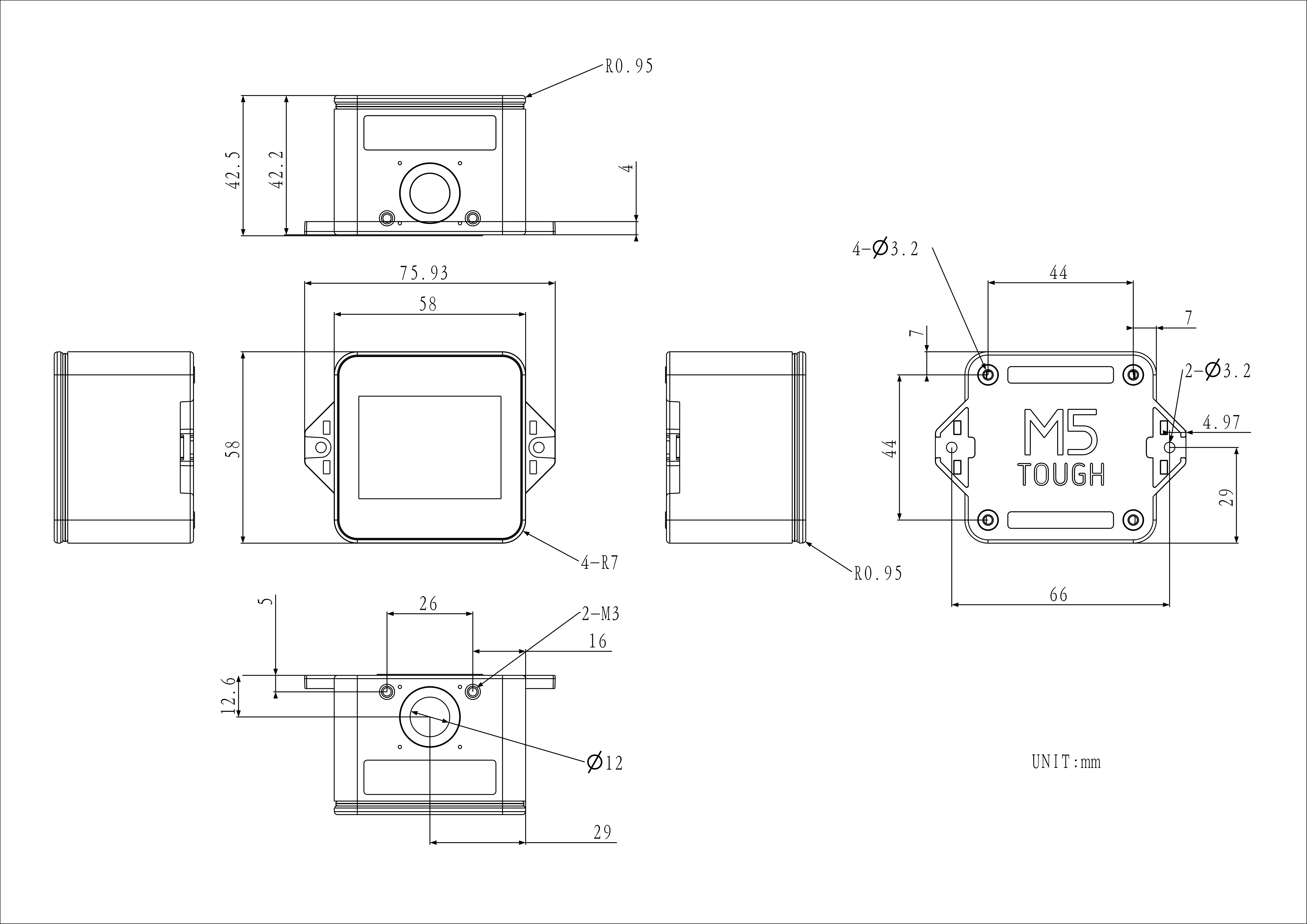
Model Size
Datasheets
Softwares
Arduino
Other
Video
Product Comparison
| Product Comparison | ToughC5 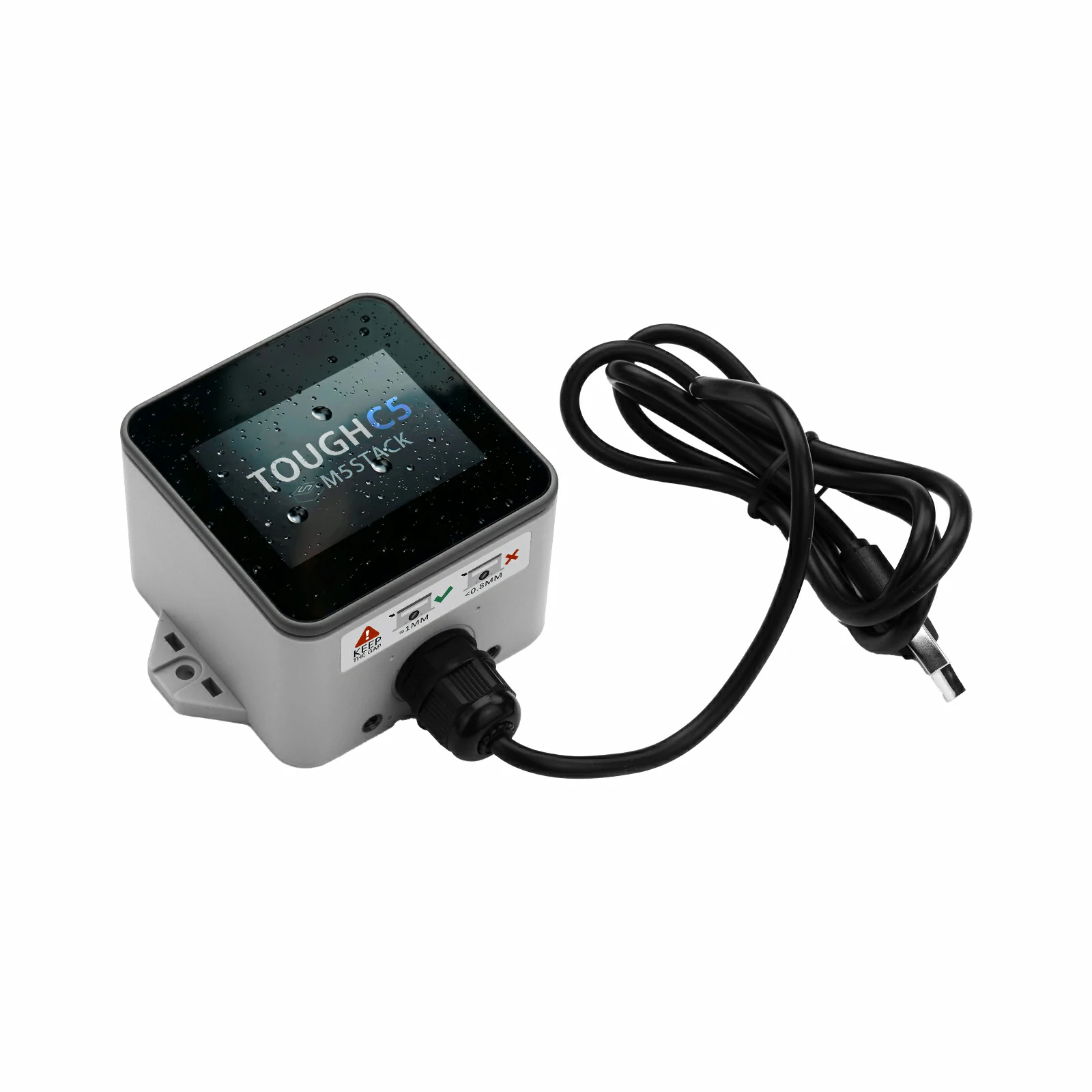 | Tough 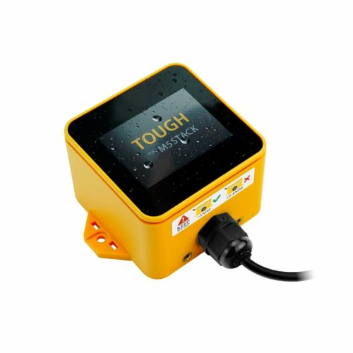 |
|---|
| SoC | ESP32-C5HR8 @ RISC-V 32-bit single-core processor, up to 240MHz | ESP32-D0WDQ6-V3 @ Xtensa 32-bit LX6 dual-core processor, up to 240MHz |
| SRAM | 384 KB HP SRAM + 16 KB LP SRAM | 520KB |
| Flash | 16MB | 16MB |
| PSRAM | 8MB Quad | 8MB Quad |
| Wireless Connectivity | 2.4 & 5 GHz dual-band Wi-Fi 6 / Zigbee / Thread (802.15.4) | 2.4 GHz Wi-Fi |
| Antenna | FPC antenna, 2.4G & 5G, IPEX-2nd Gen, 14.3 x 5.3mm, cable length 50mm | 3D Wi-Fi antenna |
| LCD Screen | 2.0" 320 x 240 ILI9342C full-color display, maximum brightness 853nit | 2.0" 320 x 240 ILI9342C full-color display, maximum brightness 853nit |
| Touch Panel Driver IC | CHSC6540 | CHSC6540 |
| Audio | Onboard passive buzzer @8530 | NS4168 16bit I2S amplifier + 1W speaker |
| PMU | M5PM1 | AXP192 |
| IO Expansion | M5IOE1 peripheral control system | / |
| RTC Clock Chip | RX8130CE | BM8563 |