

Arduino Quick Start
2. Devices & Examples
3. M5Unified
4. M5GFX
5. Extensions
Unit
Module
Atomic
Tab5
IoT
Accessories
ToughC5 M5PM1 & M5IOE1 Power Management
1. Multi-Level Power Switching Design
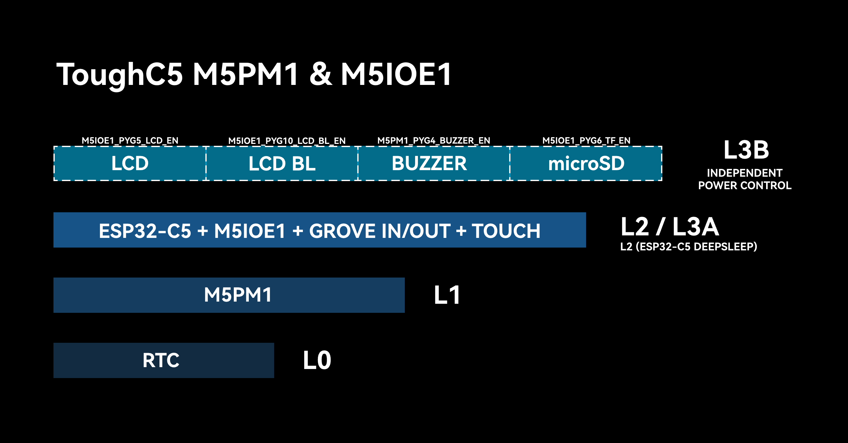
ToughC5 integrates M5PM1 and M5IOE1 to provide multi-level power switching through its hardware circuits. Each level corresponds to a different controller state and power state for peripherals and interfaces. You can switch the controller state and related power enables as needed, turning off unused peripherals to reduce overall power consumption.
M5PM1 / M5IOE1 Driver Libraries
The M5PM1 and M5IOE1 libraries make it easy to configure their pin functions for low-power wakeup and peripheral power control.
L0
At this power level, the RTC is powered by a coin-cell battery to keep the clock running. This level remains powered as long as the coin-cell battery is not depleted.
L1
At this power level, the system battery is connected and M5PM1 remains powered to manage power for the entire device. The controller and peripherals at subsequent levels can be enabled as needed.
L2 / L3A
At this level, power is enabled for ESP32-C5, the M5IOE1 expansion chip, the GROVE input / output interface, and the touchscreen, while M5PM1 and the RTC remain powered. This level uses the M5PM1 DC-DC output 3V3_L2 to power ESP32-C5 and M5IOE1, and the LDO output 3V3_L2_LDO to power the touchscreen. The following APIs control these two power outputs.
pm1.setDcdcEnable(true); // L2 ON
pm1.setDcdcEnable(false); // L2 OFF
pm1.setLdoEnable(true); // L2 LDO ON
pm1.setLdoEnable(false); // L2 LDO OFFWhen ESP32-C5 is in deep sleep, the system is at level L2. ESP32-C5, M5IOE1, and the touchscreen remain powered, while M5BUS 3V3 is not enabled. When ESP32-C5 is active, the system is at level L3A and M5BUS 3V3 is enabled. Both belong to the same power-supply level and are distinguished by the controller's operating state. ESP32-C5 can control M5PM1 to enter sleep and shut off its own power (L2 -> L1/L0).
L3B
Level L3B controls power or related settings for peripherals such as the LCD, buzzer, and Grove. Control is implemented through the M5IOE1 I/O expander, allowing some peripherals at this level to be controlled independently.
| M5IOE1 | PYG1 | PYG3 | PYG4_ADC2 | PYG5_ADC3 | PYG6 | PYG10_PWM4 | PYG14 |
|---|---|---|---|---|---|---|---|
| Charger | PYB_CHG_PROG | PYB_CHG_STAT | |||||
| LCD | PYB_LCD_RST | PYB_LCD_EN | |||||
| LCD BL | PYB_BL_EN | ||||||
| microSD | PYB_TF_EN | PYB_TF_DET |
- PYB_CHG_PROG: Charge-current setting control
- PYB_CHG_STAT: Charge-status input; low indicates charging
- PYB_LCD_RST: LCD reset
- PYB_LCD_EN: LCD power enable
- PYB_BL_EN: LCD backlight enable
- PYB_TF_EN: microSD power enable
- PYB_TF_DET: microSD detection; low indicates a card is detected
Control peripheral power independently with the M5IOE1 APIs below:
ioe1.pinMode(M5IOE1_PIN_6, OUTPUT);
ioe1.digitalWrite(M5IOE1_PIN_6, HIGH);2. M5PM1 Sleep
Manual Sleep
M5PM1 can be put into sleep mode by the program to reduce overall power consumption. By default, entering sleep directly returns the system to power level L0, where only M5PM1 remains powered.
pm1.shutdown();For use cases that need low-power circuits such as touch wakeup to remain active, configure the required power-retention state and wakeup source before putting M5PM1 into sleep mode. ToughC5 has no physical buttons, so wakeup from sleep is performed through the touchscreen. See the M5PM1 wakeup sections below for configuration details.
I2C Idle Sleep
M5PM1 can be configured to enter sleep automatically when I2C communication is idle, reducing overall power consumption. After it enters sleep, the first communication from ESP32-C5 is used to wake M5PM1 and may fail. Communication succeeds on the next transaction after wakeup.
m5pm1_err_t setI2cSleepTime(uint8_t seconds);3. M5PM1 Timer
M5PM1 supports a timer that can trigger an operation when the countdown ends, such as powering on, powering off, or resetting.
m5pm1_err_t timerSet(uint32_t seconds, m5pm1_tim_action_t action);typedef enum {
M5PM1_TIM_ACTION_STOP = 0b000, // Stop, no action
M5PM1_TIM_ACTION_FLAG = 0b001, // Set flag only
M5PM1_TIM_ACTION_REBOOT = 0b010, // System reboot
M5PM1_TIM_ACTION_POWERON = 0b011, // Power on
M5PM1_TIM_ACTION_POWEROFF = 0b100 // Power off
} m5pm1_tim_action_t;Timed Power-On / Power-Off Example
Example: Configure the timer by touching the left or right side of the screen. Touch the left side to set a 10-second timer, after which the device powers on again and immediately powers off. Touch the right side to set a 10-second timer before powering off; press the power button to turn it on again.
#include <M5Unified.h>
#include <M5PM1.h>

M5PM1 pm1;

void setup(void)
{
    auto cfg = M5.config();
    cfg.clear_display = false;
    M5.begin(cfg);
    Serial.begin(115200);
    M5.Display.setRotation(1);
    M5.Display.setTextDatum(middle_center);
    M5.Display.setTextColor(TFT_BLACK, TFT_WHITE);
    M5.Display.setFont(&fonts::FreeSansBold12pt7b);
    M5.Display.clear(TFT_WHITE);
    M5.Display.drawString("Timer Power Test", M5.Display.width() / 2, 30);
    M5.Display.setFont(&fonts::FreeSansBold9pt7b);
    M5.Display.drawString("Touch left: Power ON after 10s", M5.Display.width() / 2, 90);
    M5.Display.drawString("Touch right: Power OFF after 10s", M5.Display.width() / 2, 140);

    const m5pm1_err_t err = pm1.begin(&M5.In_I2C, M5PM1_DEFAULT_ADDR, M5PM1_I2C_FREQ_400K);
    if (err != M5PM1_OK) {
        Serial.printf("M5PM1 init failed: %d\n", err);
        while (true) {
            delay(1000);
        }
    }
    Serial.println("M5PM1 initialized");
}

void loop(void)
{
    M5.update();
    if (!M5.Touch.getCount()) {
        return;
    }

    const auto touch = M5.Touch.getDetail(0);
    if (!touch.wasClicked()) {
        return;
    }

    M5.Display.clear(TFT_WHITE);
    M5.Display.setTextDatum(middle_center);
    M5.Display.setTextColor(TFT_BLACK, TFT_WHITE);
    M5.Display.setFont(&fonts::FreeSansBold12pt7b);
    if (touch.x < M5.Display.width() / 2) {
        M5.Display.drawString("Power ON after 10s", M5.Display.width() / 2, 120);
        Serial.println("Touch left: power on timer set for 10 seconds");
        const m5pm1_err_t timerErr = pm1.timerSet(10, M5PM1_TIM_ACTION_POWERON);
        Serial.printf("Power on timer result: %d\n", timerErr);
        delay(200);
        Serial.println("Requesting shutdown");
        pm1.shutdown();
    } else {
        M5.Display.drawString("Power OFF after 10s", M5.Display.width() / 2, 120);
        Serial.println("Touch right: power off timer set for 10 seconds");
        const m5pm1_err_t timerErr = pm1.timerSet(10, M5PM1_TIM_ACTION_POWEROFF);
        Serial.printf("Power off timer result: %d\n", timerErr);
    }

    delay(20);
}4. RTC Wakeup
RTC Wakeup of M5PM1
When power switches to L1 mode, the ToughC5 RTC and M5PM1 remain powered. When RTC timed wakeup is configured, M5PM1 enters sleep while retaining the L1 power required for the RTC to operate.
The RTC timer can then trigger wakeup. The RTC's PM_RTC_INT interrupt is connected to M5PM1 GPIO3, triggering M5PM1 to wake and power ESP32-C5 on again.
After M5PM1 wakes, it runs the L1, L2, and L3A power-up sequence again, and ESP32-C5 repeats initialization.
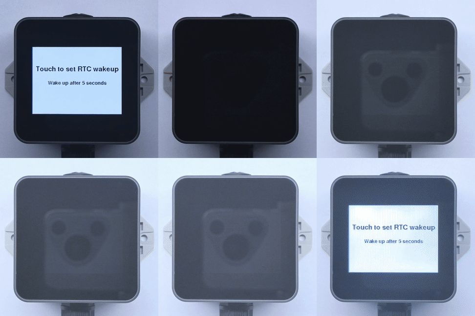
Example: After startup, touch the screen once to configure RTC timed wakeup and put M5PM1 into sleep. The RTC wakes the system after 5 seconds, M5PM1 restores power, and ESP32-C5 powers up again.
#include <M5Unified.h>
#include <M5PM1.h>

M5PM1 pm1;

void setup(void)
{
    M5.begin();
    Serial.begin(115200);
    // Initialize PM1
    m5pm1_err_t err = pm1.begin(&M5.In_I2C, M5PM1_DEFAULT_ADDR, M5PM1_I2C_FREQ_400K);

    if (err == M5PM1_OK) {
        Serial.println("PM1 initialization successful");
        pm1.gpioSetWakeEnable(M5PM1_GPIO_NUM_3, true);
        pm1.gpioSetWakeEdge(M5PM1_GPIO_NUM_3, M5PM1_GPIO_WAKE_FALLING);  // Falling edge
    } else {
        Serial.printf("PM1 initialization failed, error code: %d\n", err);
    }

    M5.Display.setTextDatum(middle_center);
    M5.Display.setTextColor(TFT_BLACK, TFT_WHITE);
    M5.Display.setFont(&fonts::FreeSansBold12pt7b);
    M5.Display.clear(TFT_WHITE);
    M5.Display.drawString("Touch to set RTC wakeup", M5.Display.width() / 2, 80);
    M5.Display.setFont(&fonts::FreeSansBold9pt7b);
    M5.Display.drawString("Wake up after 5 seconds", M5.Display.width() / 2, 130);
}

void loop(void)
{
    M5.update();
    if (M5.Touch.getCount() && M5.Touch.getDetail(0).wasClicked()) {
        M5.Rtc.clearIRQ();
        if (!M5.Rtc.setTimerIRQ(5000)) {
            M5.Display.clear(TFT_WHITE);
            M5.Display.drawString("RTC timer failed", M5.Display.width() / 2, 120);
            return;
        }
        Serial.println("RTC IRQ enabled successfully");
        M5.Display.clear(TFT_WHITE);
        M5.Display.drawString("5s later wakeup", M5.Display.width() / 2, 120);
        pm1.setLdoEnable(true);
        pm1.ldoSetPowerHold(true);
        delay(50);
        pm1.shutdown();
    }
}After the screen is touched, the program clears the RTC interrupt and sets a 5-second timer. It then keeps M5PM1 at power level L1 and turns off the rest of the system. When the timer expires, the RTC triggers M5PM1 GPIO3 through PM_RTC_INT. M5PM1 restores power, and ESP32-C5 repeats initialization.
RTC Wakeup of ESP32-C5
The configuration for RTC wakeup of ESP32-C5 is similar to RTC wakeup of M5PM1. The difference is that the RTC interrupt does not directly power the system back on. Instead, it uses the RTC IRQ -> M5PM1 GPIO3 -> M5PM1 GPIO1 IRQout -> ESP32-C5 G4 signal path:
- Configure M5PM1 GPIO3 as an input. This pin is connected to the RTC
PM_RTC_INTinterrupt signal. - Configure M5PM1 GPIO1 as the
IRQoutoutput signal pin. When the state of GPIO3 (the RTC interrupt signal) changes, GPIO1IRQoutoutputs an interrupt signal. - Configure ESP32-C5 to enter sleep and set G4 as the wakeup pin.
- When the RTC timer expires, the RTC wakeup signal triggers M5PM1 GPIO1
IRQout, which wakes ESP32-C5.
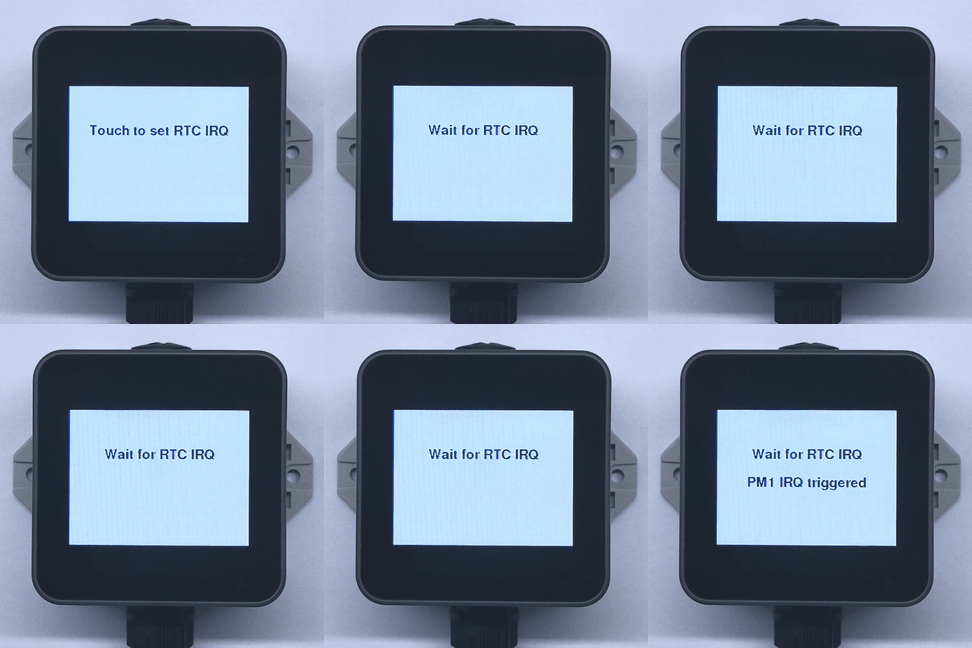
Example: After startup, touch the screen to configure a 5-second RTC timer. When the timer expires, it triggers the GPIO interrupt handler. If you enable the deep-sleep code that is commented out, the RTC timer wakes ESP32-C5, which then runs setup() again.
#include <M5Unified.h>
#include <M5PM1.h>
#include "driver/rtc_io.h"

M5PM1 pm1;

void setup(void)
{
    M5.begin();
    Serial.begin(115200);
    // Initialize PM1
    m5pm1_err_t err = pm1.begin(&M5.In_I2C, M5PM1_DEFAULT_ADDR, M5PM1_I2C_FREQ_400K);

    if (err == M5PM1_OK) {
        Serial.println("PM1 initialization successful");
        pm1.irqClearGpioAll();
        pm1.irqClearSysAll();
        pm1.irqClearBtnAll();

        pm1.irqSetGpioMaskAll(M5PM1_IRQ_MASK_ENABLE);
        pm1.irqSetSysMaskAll(M5PM1_IRQ_MASK_ENABLE);
        pm1.irqSetBtnMaskAll(M5PM1_IRQ_MASK_ENABLE);

        pm1.irqSetGpioMask(M5PM1_IRQ_GPIO3, M5PM1_IRQ_MASK_DISABLE);
        pm1.gpioSetMode(M5PM1_GPIO_NUM_3, M5PM1_GPIO_MODE_INPUT);
        pm1.gpioSetPull(M5PM1_GPIO_NUM_3, M5PM1_GPIO_PULL_UP);

        pm1.gpioSetMode(M5PM1_GPIO_NUM_1, M5PM1_GPIO_MODE_OUTPUT);
        pm1.gpioSetDrive(M5PM1_GPIO_NUM_1, M5PM1_GPIO_DRIVE_PUSHPULL);
        pm1.gpioSetFunc(M5PM1_GPIO_NUM_1, M5PM1_GPIO_FUNC_IRQ);
    } else {
        Serial.printf("PM1 initialization failed, error code: %d\n", err);
    }

    M5.Display.setTextDatum(middle_center);
    M5.Display.setTextColor(TFT_BLACK, TFT_WHITE);
    M5.Display.setFont(&fonts::FreeSansBold12pt7b);
    M5.Display.clear(TFT_WHITE);
    M5.Display.drawString("Touch to set RTC IRQ", M5.Display.width() / 2, 80);
    M5.Rtc.clearIRQ();
}

volatile bool pm1IrqTriggered = false;

void ARDUINO_ISR_ATTR pm1_irq_handler() {
    pm1IrqTriggered = true;
}

void loop(void)
{
    M5.update();

    if (pm1IrqTriggered) {
        pm1IrqTriggered = false;
        M5.Rtc.clearIRQ();
        M5.Rtc.setTimerIRQ(0);
        pm1.irqClearGpioAll();
        pm1.irqClearSysAll();
        pm1.irqClearBtnAll();
        Serial.println("PM1 IRQ triggered");
        M5.Display.drawString("PM1 IRQ triggered", M5.Display.width() / 2, 130);
    }

    if (M5.Touch.getCount() && M5.Touch.getDetail(0).wasClicked()) {
        if (!M5.Rtc.setTimerIRQ(5000)) {
            M5.Display.clear(TFT_WHITE);
            M5.Display.drawString("RTC timer failed", M5.Display.width() / 2, 100);
            Serial.println("Failed to enable RTC IRQ");
            return;
        }
        Serial.println("RTC IRQ enabled successfully");
        M5.Display.clear(TFT_WHITE);
        M5.Display.drawString("Wait for RTC IRQ", M5.Display.width() / 2, 80);
        // Choose either of the two pieces of code below.
        pinMode(GPIO_NUM_4, INPUT_PULLUP);
        attachInterrupt(GPIO_NUM_4, pm1_irq_handler, FALLING);

        // esp_sleep_enable_ext0_wakeup(GPIO_NUM_4, 0);  // 0 = Low
        // rtc_gpio_pullup_en(GPIO_NUM_4);
        // Serial.println("Going to sleep now");
        // esp_deep_sleep_start();
    }
}When the RTC interrupt occurs, M5PM1 GPIO1 outputs an IRQ signal. ESP32-C5 G4 detects the low level and wakes the device from deep sleep. ESP32-C5 then resets, and the program starts from setup().
5. TP Wakeup
TP Wakeup of M5PM1
When power switches to L2 / L3A mode, the ToughC5 touch circuit and M5PM1 remain powered. When touch wakeup is configured, M5PM1 enters sleep while retaining the 3V3_L2_LDO touch supply so touch detection remains active.
Touching the screen then generates a wakeup signal. The touch interrupt PM_TP_INT is connected to M5PM1 GPIO0, which wakes M5PM1 and powers ESP32-C5 on again.
After M5PM1 wakes, it runs the L1, L2, and L3A power-up sequence again, and ESP32-C5 repeats initialization.
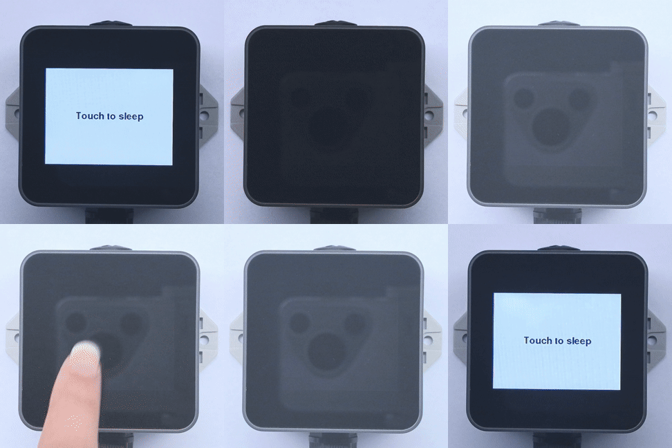
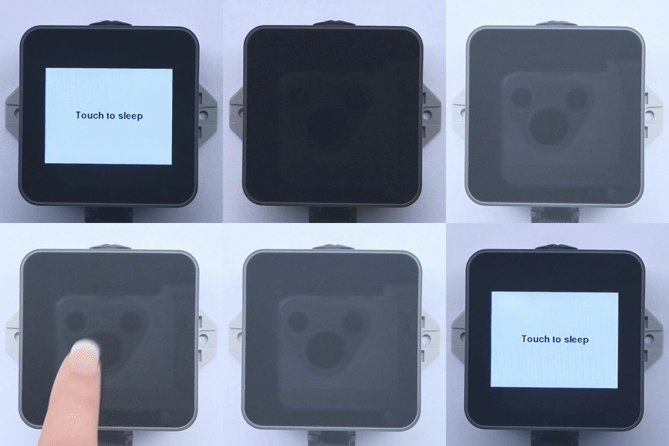
Example: After startup, touch the screen once to configure touch wakeup and retain the M5PM1 LDO supply. M5PM1 enters sleep. Touch the screen again to trigger TP wakeup; M5PM1 restores power and ESP32-C5 powers up again.
#include <M5PM1.h>
#include <M5Unified.h>

M5PM1 pm1;

void setup(void)
{
    M5.begin();
    Serial.begin(115200);

    if (pm1.begin(&M5.In_I2C, M5PM1_DEFAULT_ADDR, M5PM1_I2C_FREQ_400K) != M5PM1_OK) {
        Serial.println("PM1 initialization failed");
        while (true) {
            delay(1000);
        }
    }

    Serial.println("PM1 initialization successful");
    M5.Display.setTextDatum(middle_center);
    M5.Display.setTextColor(TFT_BLACK, TFT_WHITE);
    M5.Display.setFont(&fonts::FreeSansBold12pt7b);
    M5.Display.clear(TFT_WHITE);
    M5.Display.drawString("Touch to sleep", M5.Display.width() / 2, 120);

    pm1.gpioSetFunc(M5PM1_GPIO_NUM_0, M5PM1_GPIO_FUNC_WAKE);
    pm1.gpioSetWakeEdge(M5PM1_GPIO_NUM_0, M5PM1_GPIO_WAKE_FALLING);
    pm1.gpioSetWakeEnable(M5PM1_GPIO_NUM_0, true);
    pm1.setLdoEnable(true);
    pm1.ldoSetPowerHold(true);
}

void loop(void)
{
    M5.update();
    if (M5.Touch.getCount() && M5.Touch.getDetail(0).wasClicked()) {
        M5.Display.clear(TFT_WHITE);
        M5.Display.drawString("Touch wakeup enabled", M5.Display.width() / 2, 120);
        delay(200);
        pm1.shutdown();
    }
}At startup, the program configures wakeup on M5PM1 GPIO0 and retains the 3V3_L2_LDO touch supply, then turns off the rest of the system after the screen is touched. Touch the screen again to trigger wakeup through PM_TP_INT and M5PM1 GPIO0. M5PM1 restores power, and ESP32-C5 repeats initialization. This example demonstrates only M5PM1 wakeup configuration; it does not read touch coordinates.
TP Wakeup of ESP32-C5
The configuration for TP wakeup of ESP32-C5 is similar to RTC wakeup of ESP32-C5. The difference is that the wakeup source is the touch interrupt PM_TP_INT, which uses the TP IRQ -> M5PM1 GPIO0 -> M5PM1 GPIO1 IRQout -> ESP32-C5 G4 signal path.
Example: After startup, touch the screen once to configure the TP interrupt and register the G4 interrupt handler. Touch the screen again to trigger the GPIO interrupt handler. If you enable the deep-sleep code that is commented out, touching the screen wakes ESP32-C5, which then runs setup() again.
#include <M5Unified.h>
#include <M5PM1.h>
#include "driver/rtc_io.h"

M5PM1 pm1;

void setup(void)
{
    M5.begin();
    Serial.begin(115200);
    // Initialize PM1
    m5pm1_err_t err = pm1.begin(&M5.In_I2C, M5PM1_DEFAULT_ADDR, M5PM1_I2C_FREQ_400K);

    if (err == M5PM1_OK) {
        Serial.println("PM1 initialization successful");
        pm1.irqClearGpioAll();
        pm1.irqClearSysAll();
        pm1.irqClearBtnAll();

        pm1.irqSetGpioMaskAll(M5PM1_IRQ_MASK_ENABLE);
        pm1.irqSetSysMaskAll(M5PM1_IRQ_MASK_ENABLE);
        pm1.irqSetBtnMaskAll(M5PM1_IRQ_MASK_ENABLE);

        pm1.irqSetGpioMask(M5PM1_IRQ_GPIO0, M5PM1_IRQ_MASK_DISABLE);
        pm1.gpioSetMode(M5PM1_GPIO_NUM_0, M5PM1_GPIO_MODE_INPUT);
        pm1.gpioSetPull(M5PM1_GPIO_NUM_0, M5PM1_GPIO_PULL_UP);

        pm1.gpioSetMode(M5PM1_GPIO_NUM_1, M5PM1_GPIO_MODE_OUTPUT);
        pm1.gpioSetDrive(M5PM1_GPIO_NUM_1, M5PM1_GPIO_DRIVE_PUSHPULL);
        pm1.gpioSetFunc(M5PM1_GPIO_NUM_1, M5PM1_GPIO_FUNC_IRQ);
    } else {
        Serial.printf("PM1 initialization failed, error code: %d\n", err);
    }

    M5.Display.setTextDatum(middle_center);
    M5.Display.setTextColor(TFT_BLACK, TFT_WHITE);
    M5.Display.setFont(&fonts::FreeSansBold12pt7b);
    M5.Display.clear(TFT_WHITE);
    M5.Display.drawString("Touch to set TP IRQ", M5.Display.width() / 2, 80);
}

volatile bool pm1IrqTriggered = false;

void ARDUINO_ISR_ATTR pm1_irq_handler() {
    pm1IrqTriggered = true;
}

void loop(void)
{
    M5.update();

    if (pm1IrqTriggered) {
        pm1IrqTriggered = false;
        pm1.irqClearGpioAll();
        pm1.irqClearSysAll();
        pm1.irqClearBtnAll();
        Serial.println("PM1 IRQ triggered");
        M5.Display.drawString("PM1 IRQ triggered", M5.Display.width() / 2, 130);
    }

    if (M5.Touch.getCount() && M5.Touch.getDetail(0).wasClicked()) {
        pm1.irqClearGpioAll();
        pm1.irqClearSysAll();
        pm1.irqClearBtnAll();
        Serial.println("TP IRQ enabled successfully");
        M5.Display.clear(TFT_WHITE);
        M5.Display.drawString("Wait for TP IRQ", M5.Display.width() / 2, 80);
        // Choose either of the two pieces of code below.
        pinMode(GPIO_NUM_4, INPUT_PULLUP);
        attachInterrupt(GPIO_NUM_4, pm1_irq_handler, FALLING);

        // esp_sleep_enable_ext0_wakeup(GPIO_NUM_4, 0);  // 0 = Low
        // rtc_gpio_pullup_en(GPIO_NUM_4);
        // Serial.println("Going to sleep now");
        // esp_deep_sleep_start();
    }
}After the screen is touched, the program clears the M5PM1 interrupt flag and registers a falling-edge interrupt on ESP32-C5 G4. Touch the screen again to forward the TP interrupt through M5PM1 GPIO0 to the GPIO1 IRQ output, triggering the G4 interrupt. The program displays the result on the screen and over the serial port.
6. M5IOE1 Peripheral Control
ToughC5's M5IOE1 controls power and related settings for some L3B peripherals, including the LCD, backlight, and microSD card. The M5IOE1 APIs let you control these peripherals independently for more flexible power management.
The main M5IOE1 pins on ToughC5 are listed below:
| M5IOE1 Pin | ToughC5 Function |
|---|---|
M5IOE1_PIN_3 | Charge-status input |
M5IOE1_PIN_4 | LCD reset |
M5IOE1_PIN_5 | LCD power enable |
M5IOE1_PIN_6 | microSD power enable |
M5IOE1_PIN_10 | LCD backlight enable |
M5IOE1_PIN_14 | microSD detection input |
The example below initializes M5IOE1 directly, then demonstrates LCD reset, LCD power, backlight, and microSD power control in sequence. It also reads the charge status and TF card detection state. PYB_TF_DET is active low; a low reading indicates that a microSD card is detected.
#include <Arduino.h>
#include <Wire.h>
#include <M5IOE1.h>

M5IOE1 ioe1;

#define IOE_CHG_STAT M5IOE1_PIN_3
#define IOE_LCD_RST  M5IOE1_PIN_4
#define IOE_LCD_EN   M5IOE1_PIN_5
#define IOE_TF_EN    M5IOE1_PIN_6
#define IOE_BL_EN    M5IOE1_PIN_10
#define IOE_TF_DET   M5IOE1_PIN_14

void setup(void)
{
    Serial.begin(115200);

    // Initialize IOE1.
    const m5ioe1_err_t ioe1_err =
        ioe1.begin(&Wire, M5IOE1_DEFAULT_ADDR_2, LP_SDA, LP_SCL,
                   M5IOE1_I2C_FREQ_100K);
    if (ioe1_err == M5IOE1_OK) {
        Serial.println("IOE1 initialization successful");
    } else {
        Serial.printf("IOE1 initialization failed, error code: %d\n", ioe1_err);
        while (true) delay(1000);
    }

    ioe1.pinMode(IOE_CHG_STAT, INPUT);
    ioe1.pinMode(IOE_LCD_RST, OUTPUT);
    ioe1.pinMode(IOE_LCD_EN, OUTPUT);
    ioe1.pinMode(IOE_TF_EN, OUTPUT);
    ioe1.pinMode(IOE_BL_EN, OUTPUT);
    ioe1.pinMode(IOE_TF_DET, INPUT_PULLUP);

    // Default states: LCD on, backlight on, and microSD power on.
    ioe1.digitalWrite(IOE_LCD_EN, HIGH);
    ioe1.digitalWrite(IOE_TF_EN, HIGH);
    ioe1.digitalWrite(IOE_BL_EN, HIGH);
    ioe1.digitalWrite(IOE_LCD_RST, LOW);
    delay(10);
    ioe1.digitalWrite(IOE_LCD_RST, HIGH);

    Serial.println("IOE1 peripheral control test begin");
}

void loop(void)
{
    // LCD reset.
    Serial.println("LCD reset LOW");
    ioe1.digitalWrite(IOE_LCD_RST, LOW);
    delay(100);
    Serial.println("LCD reset HIGH");
    ioe1.digitalWrite(IOE_LCD_RST, HIGH);
    delay(1000);

    // LCD and backlight power.
    Serial.println("LCD and backlight power OFF");
    ioe1.digitalWrite(IOE_BL_EN, LOW);
    ioe1.digitalWrite(IOE_LCD_EN, LOW);
    delay(1000);
    Serial.println("LCD and backlight power ON");
    ioe1.digitalWrite(IOE_LCD_EN, HIGH);
    ioe1.digitalWrite(IOE_BL_EN, HIGH);
    delay(1000);

    // microSD power.
    Serial.println("microSD power OFF");
    ioe1.digitalWrite(IOE_TF_EN, LOW);
    delay(1000);
    Serial.println("microSD power ON");
    ioe1.digitalWrite(IOE_TF_EN, HIGH);
    delay(1000);

    const int chargeState = ioe1.digitalRead(IOE_CHG_STAT);
    const int tfState = ioe1.digitalRead(IOE_TF_DET);
    Serial.printf("CHG_STAT: %d, TF_DET: %d\n", chargeState, tfState);
}After a successful upload, the program demonstrates LCD reset, LCD and backlight power, and microSD power control in sequence. It outputs the charge status and TF card detection state over the serial port.