
Stamp IO
SKU:S002
Description
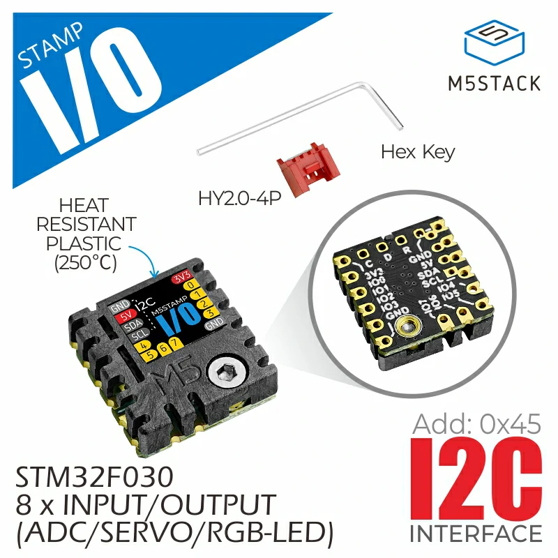
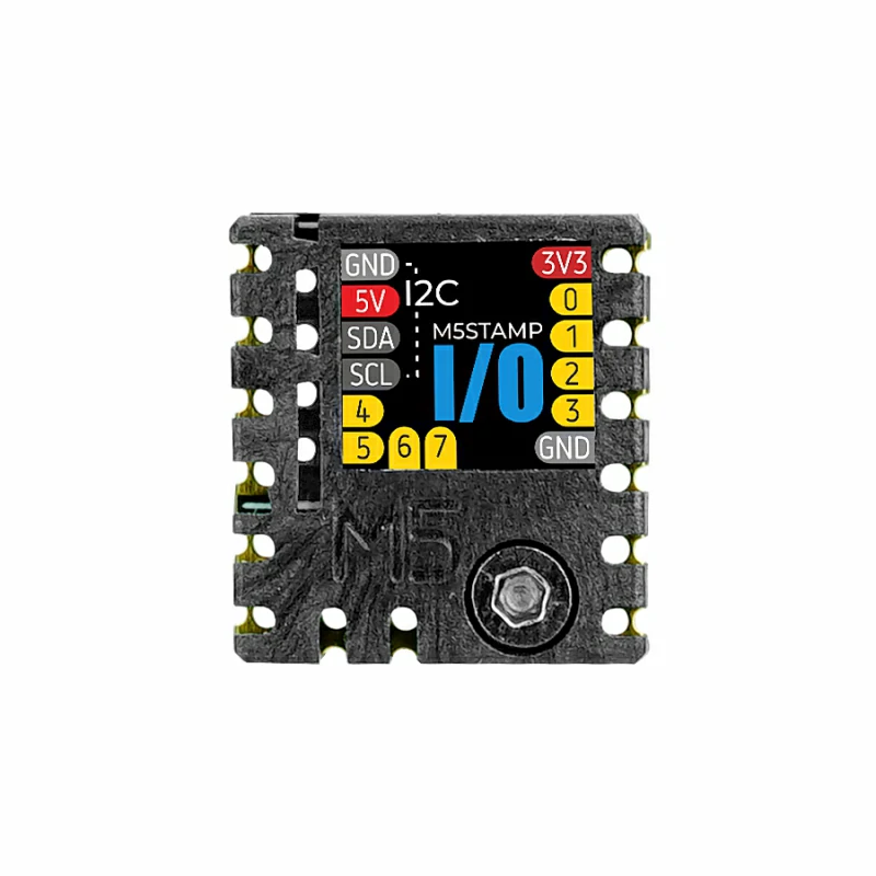
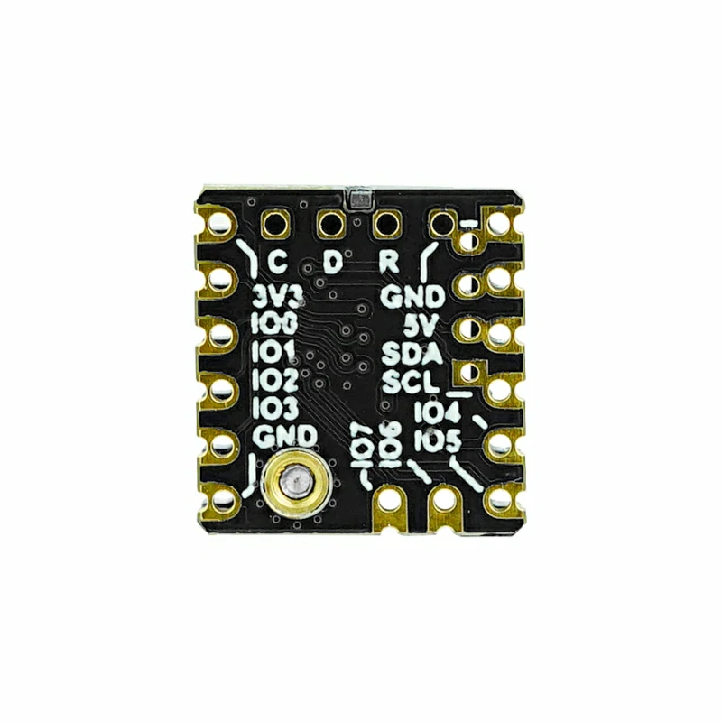
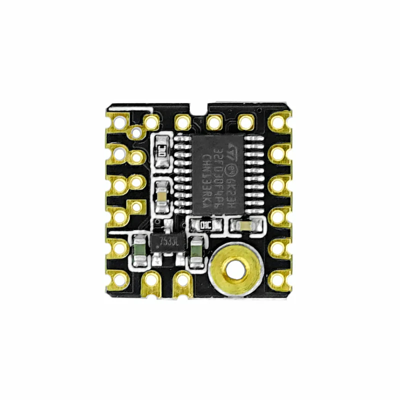
Stamp IO is an IO expansion board based on the STM32F030 microcontroller, utilizing an I2C communication interface to provide 8 channels of IO expansion. Each IO channel supports independent configuration for digital input/output, ADC, SERVO control, and RGB LED control modes. It is suitable for applications such as multi-channel digital/analog signal acquisition and light/servo control.
Features
- 8-channel input/output expansion:
- Digital input/output
- ADC input
- SERVO control (PWM)
- RGB LED control
- IO pin PWM output function
- I2C communication interface:
- Supports I2C address configuration
- Multiple forms:
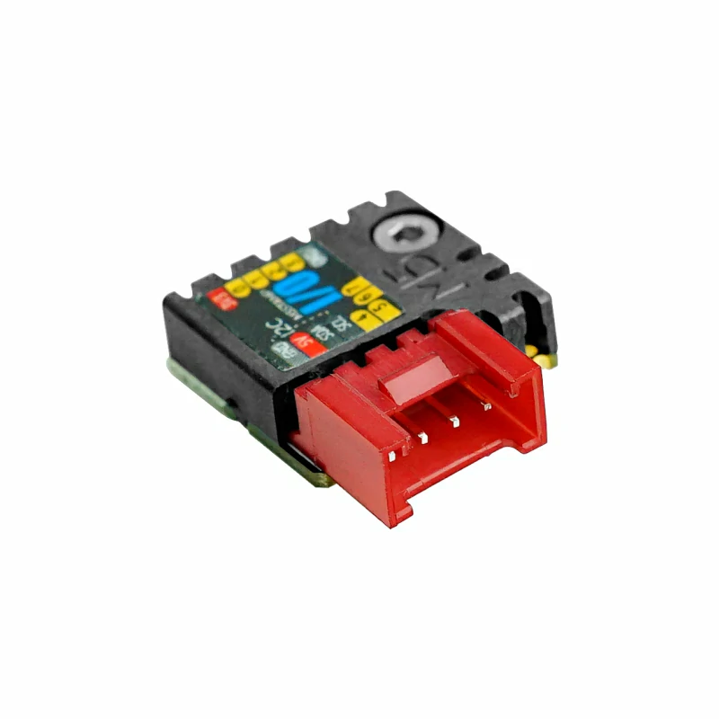
- Supports various application forms (SMT, DIP, flying leads)
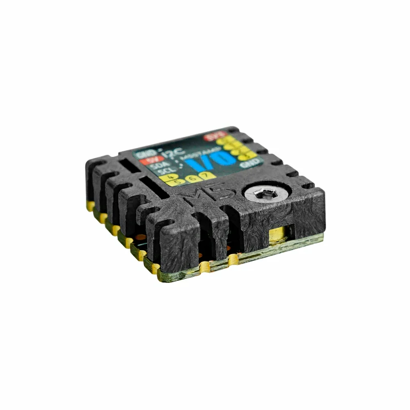
- Equipped with high-temperature plastic armor, supports SMT reflow temperature (230°C)
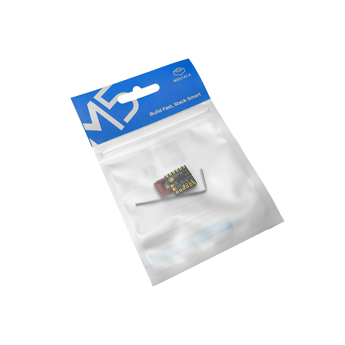
Includes
- 1 x Stamp IO
- 1 x HY2.0-4P female connector (red)
- 1 x L-shaped hex key 1.5mm (compatible with M2 screws)
Applications
- IO expansion
- Servo control
- Multi-channel light control
- Multi-channel analog signal acquisition
Specifications
| Specification | Parameter |
|---|---|
| MCU | STM32F030F4P6 |
| Communication Interface | I2C @0x45 |
| IO Expansion Quantity | 8 |
| IO Supported Modes | Digital Input / Output, ADC, SERVO Control, RGB LED Control |
| IO Supported I/O Level | 3.3V |
| Product Size | 15.0 x 4.7 x 16.0mm |
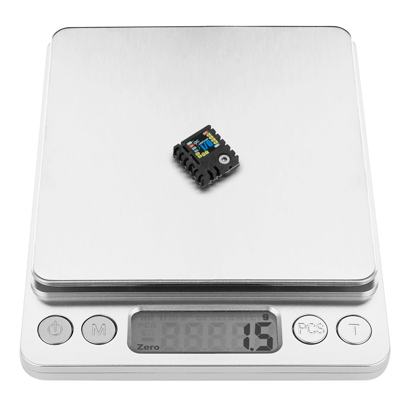
| Product Weight | 1.5g |
| Package Size | 138.0 x 93.0 x 10.0mm |
| Gross Weight | 4.9g |
Learn
Shell Supports Reflow Soldering Temperature Curve
Schematics
1/1
Model Size
Softwares
Arduino
Internal Firmware
Protocol
Page Tools