

Unit LCD
SKU:U120

Description
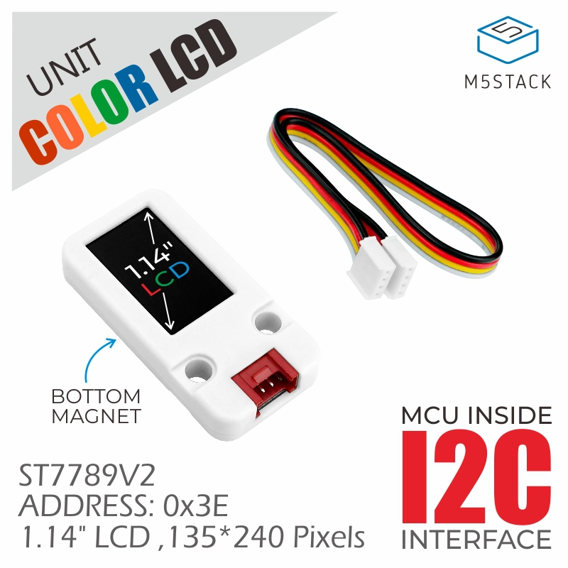
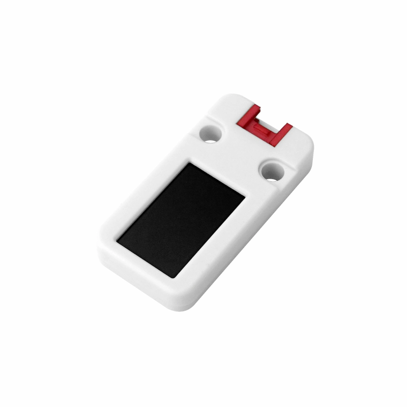
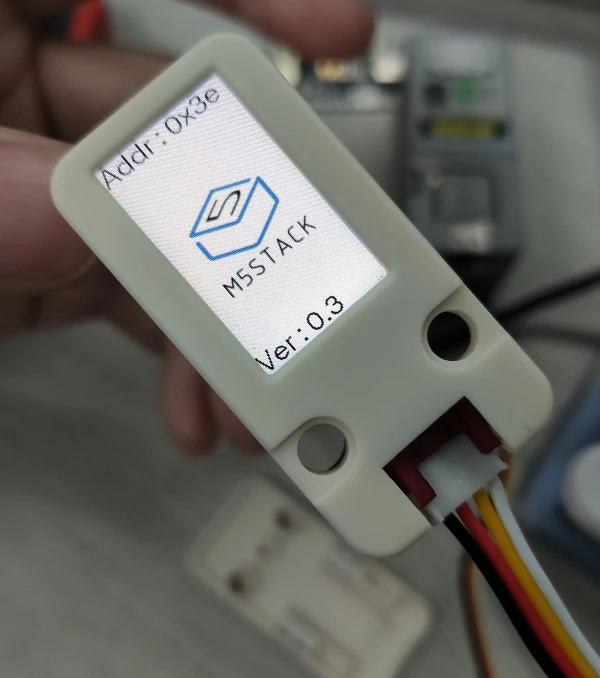
Unit LCD is a 1.14-inch color LCD expansion display unit. It uses the ST7789V2 driver solution with a resolution of 135 x 240 and supports RGB666 display (262,144 colors). It integrates an ESP32-PICO control core internally (with built-in firmware, making display development more convenient), and supports control and firmware upgrades via the I2C communication interface (addr: 0x3E). A magnetic attachment design is integrated on the back of the screen, allowing it to be easily fixed to metal surfaces. This LCD expansion display is suitable for embedding into various instruments or control devices that require simple content display as a display panel.
Features
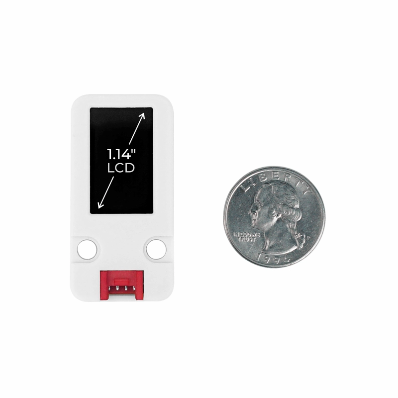
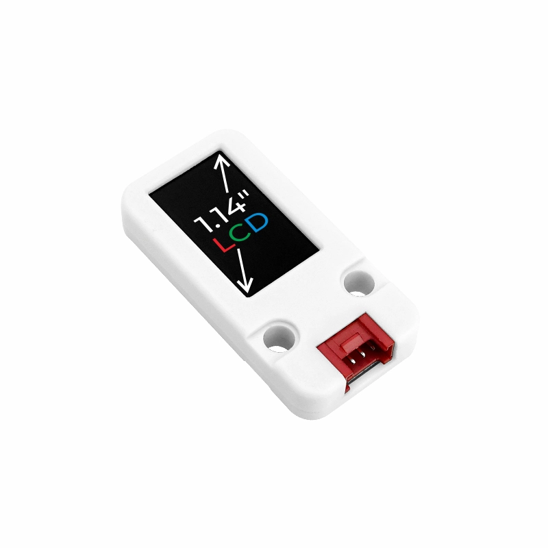
- 1.14 inch color LCD display panel
- I2C communication interface
- Viewing angle: full viewing angle
- Rear magnetic attachment design
- Supports I2C firmware upgrade
Includes
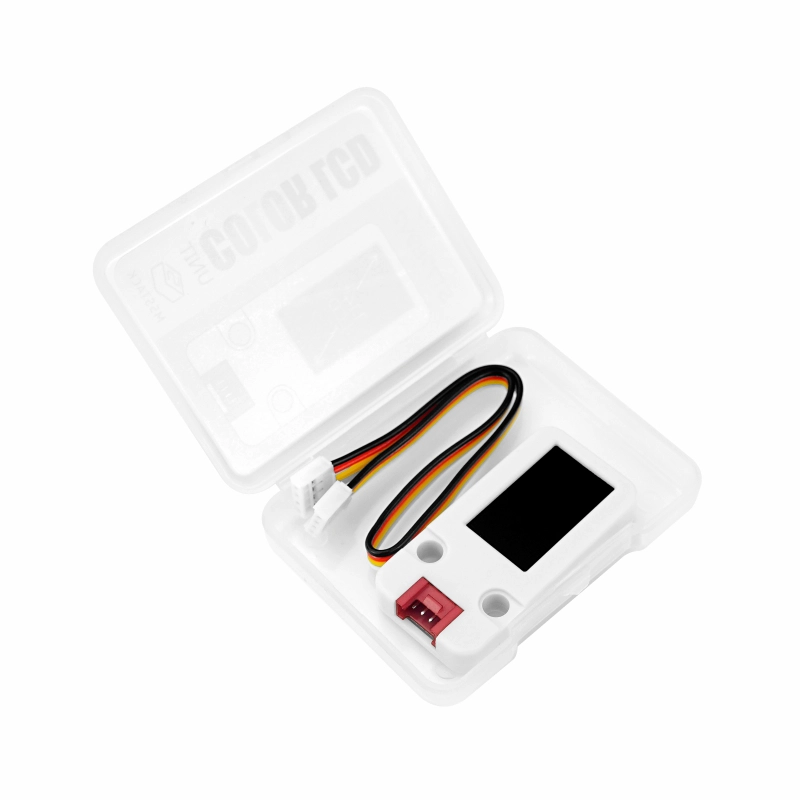
- 1 x Unit LCD
- 1 x HY2.0-4P Grove Cable (20cm)
Applications
- Information display screen
Specifications
| Specification | Parameter |
|---|---|
| Display Driver IC | ST7789V2 |
| Operating Current | 45.7mA |
| Communication Interface | I2C @ 0x3E |
| Display Size | 1.14 inch |
| Pixel Pitch | 0.1101 (H) x 0.1038 (V) mm |
| Resolution | 135 x 240 |
| Viewing Angle | Full viewing angle |
| Operating Temperature | 0 ~ 60°C |
| Housing Material | Plastic (PC) |
| Product Size | 48.0 x 24.0 x 8.0mm |
| Product Weight | 8.6g |
| Package Size | 68.0 x 57.0 x 17.0mm |
| Gross Weight | 21.3g |
Schematics
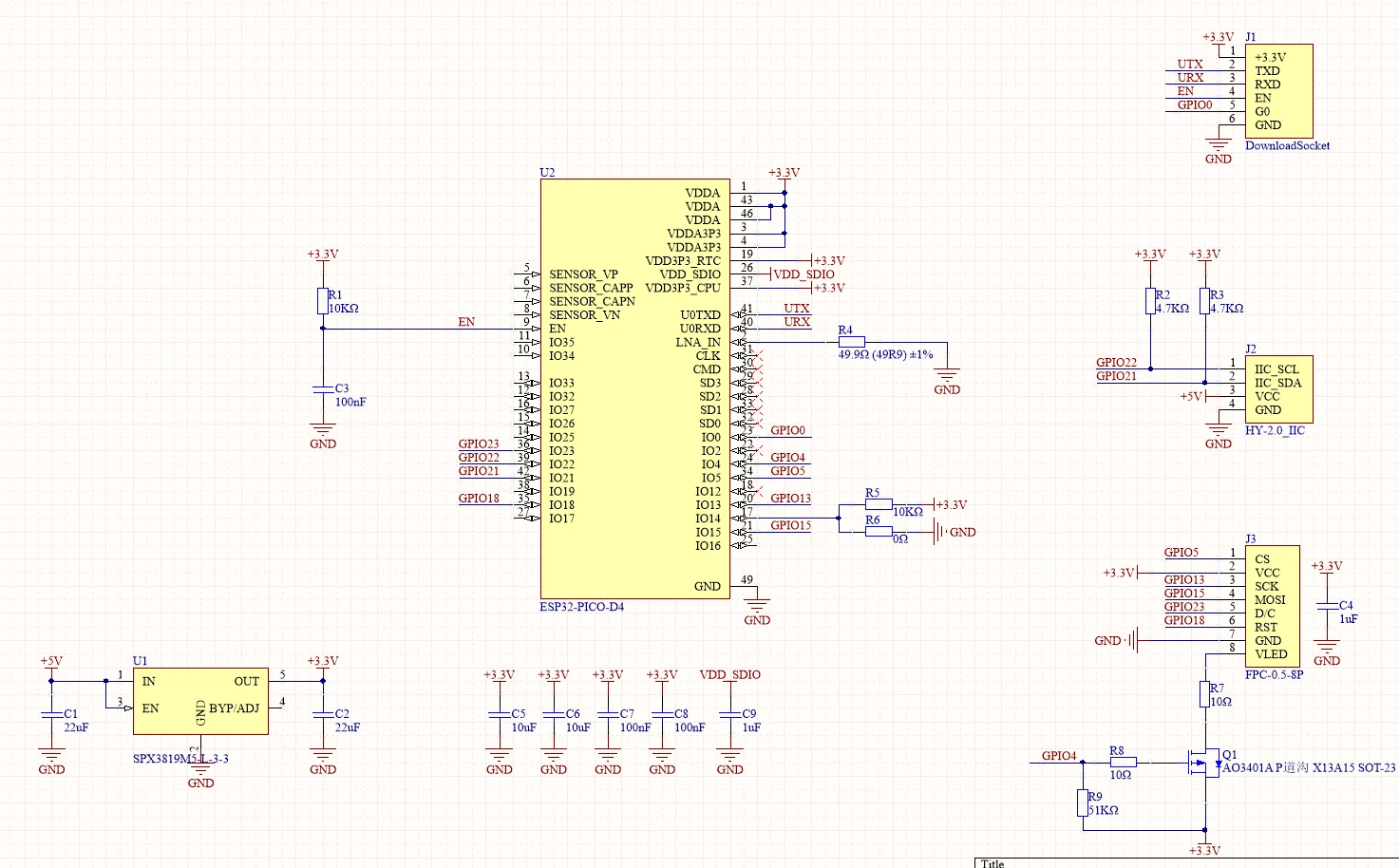
PinMap
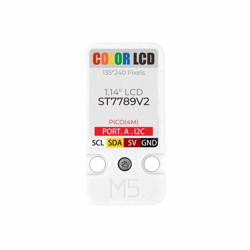
Unit LCD
| HY2.0-4P | Black | Red | Yellow | White |
|---|---|---|---|---|
| PORT.A | GND | 5V | SDA | SCL |
Model Size

Datasheets
Softwares
Arduino
#include <M5UnitLCD.h>

M5UnitLCD display;

M5Canvas canvas(&display);

static constexpr char text[] = "Hello world ! こんにちは世界! this is long long string sample. 寿限無、寿限無、五劫の擦り切れ、海砂利水魚の、水行末・雲来末・風来末、喰う寝る処に住む処、藪ら柑子の藪柑子、パイポ・パイポ・パイポのシューリンガン、シューリンガンのグーリンダイ、グーリンダイのポンポコピーのポンポコナの、長久命の長助";
static constexpr size_t textlen = sizeof(text) / sizeof(text[0]);
int textpos = 0;
int scrollstep = 2;

void setup(void)
{
  display.init();
  display.setRotation(2);
  canvas.setColorDepth(1); // mono color
  canvas.setFont(&fonts::lgfxJapanMinchoP_32);
  canvas.setTextWrap(false);
  canvas.setTextSize(2);
  canvas.createSprite(display.width() + 64, 72);
}

void loop(void)
{
  int32_t cursor_x = canvas.getCursorX()-scrollstep;
  if (cursor_x <= 0)
  {
    textpos = 0;
    cursor_x = display.width();
  }

  canvas.setCursor(cursor_x, 0);
  canvas.scroll(-scrollstep, 0);
  while (textpos < textlen && cursor_x <= display.width())
  {
    canvas.print(text[textpos++]);
    cursor_x = canvas.getCursorX();
  }
  display.waitDisplay();
  canvas.pushSprite(&display, 0, (display.height()-canvas.height()) >> 1);
}Internal Firmware
Protocol
About Unit LCD
- Unit LCD is an I2C unit with ESP32 and ST7789V2.
- It has an IPS panel with a resolution of 135 x 240.
- The number of displayable colors is 262,144 in RGB666, which is a specification of the ST7789V2.
- ESP32 handles I2C communication and draws the framebuffer in memory based on received content.
- The frame buffer content in ESP32 memory is reflected on the ST7789V2 via SPI DMA transfer.
- It is represented by RGB888 16,777,216 colors on the framebuffer.
About I2C Communication
- You can send commands to the Unit LCD and receive data using I2C communication.
- The maximum I2C communication speed is 400kHz.
- The initial value of the I2C 7-bit address is 0x3E, and it can be changed using the CHANGE_ADDR command.
- The number of bytes to send depends on the command. Some commands complete within 1 byte, while others require 7 bytes. There are also variable-length commands that continue until communication stops.
- If an I2C communication STOP or RESTART occurs during command transmission, the interrupted command will not be processed. It must be transmitted continuously to the end in a single transmission sequence.
- After sending a fixed-length command, another command can be sent consecutively.
- After sending a variable-length command, I2C communication must be stopped to indicate the end of the command.
- If a NOP command or an undefined command is sent, the communication content will be ignored until I2C communication stops.
- Since the I2C communication unit and the drawing processing unit operate in parallel, I2C communication can be executed even during drawing processing.
- I2C communication content is stored in the command buffer in ESP32 memory and processed sequentially by the drawing processing unit.
- You should use the READ_BUFCOUNT command to check the remaining buffer capacity, as sending a large amount of heavy processing such as extensive fills or range copies may overflow the buffer.
About Drawing
- You can draw rectangles by filling any area with a single color using FILLRECT.
- If you want to draw just one pixel, you can use DRAWPIXEL instead of FILLRECT.
- If you use a command that omits the foreground color, the last used color will be applied.
- You can specify the drawing range using CASET and RASET, and send image data using the WRITE_RAW command.
- You can use WRITE_RLE instead of WRITE_RAW to send run-length encoded image data.
Command List
※ Undefined commands are treated as no-operation instructions.
| hex | len | command | description | send params |
|---|---|---|---|---|
| 0x00 | 1-∞ | NOP | Do nothing until communication stops | [0] 0x00 [1-∞] Ignored value |
| 0x20 | 1 | INVOFF | Disable color inversion | [0] 0x20 |
| 0x21 | 1 | INVON | Enable color inversion | [0] 0x21 |
| 0x22 | 2 | BRIGHTNESS | Backlight brightness setting 0:Off-255:Full lights | [0] 0x22 [1] Brightness (0-255) |
| 0x23 | 7 | COPYRECT | Copy rectangular area | [0] 0x23 [1] Copy source X_Left [2] Copy source Y_Top [3] Copy source X_Right [4] Copy source Y_Bottom [5] Copy destination X_Left [6] Copy destination Y_Top |
| 0x2A | 3 | CASET | X range selection | [0] 0x2A [1] X_Left [2] X_Right |
| 0x2B | 3 | RASET | Y range selection | [0] 0x2B [1] Y_Top [2] Y_Bottom |
| 0x36 | 2 | ROTATE | Set drawing orientation 0:Normal / 1:90° / 2:180° / 3:270° 4-7: flips 0-3 | [0] 0x36 [1] Setting value (0-7) |
| 0x38 | 2 | SET_POWER | Operating speed setting (power consumption setting) 0:Low / 1:Normal / 2:High | [0] 0x38 [1] Setting value (0-2) |
| 0x39 | 2 | SET_SLEEP | LCD panel sleep setting 0: wake up / 1: sleep | [0] 0x39 [1] Setting value (0-1) |
| 0x41 | 2-∞ | WRITE_RAW_8 | Write image RGB332 | [0] 0x41 [1] RGB332 until communication STOP. |
| 0x42 | 3-∞ | WRITE_RAW_16 | Write image RGB565 | [0] 0x42 [1-2] RGB565 until communication STOP. |
| 0x43 | 4-∞ | WRITE_RAW_24 | Write image RGB888 | [0] 0x43 [1-3] RGB888 until communication STOP. |
| 0x44 | 5-∞ | WRITE_RAW_32 | Write image ARGB8888 | [0] 0x44 [1-4] ARGB8888 until communication STOP. |
| 0x45 | 2-∞ | WRITE_RAW_A | Write image A8 alpha channel only. Use the last drawing color. | [0] 0x45 [1] A8 until communication STOP. |
| 0x49 | 3-∞ | WRITE_RLE_8 | Write RLE image RGB332 | [0] 0x49 [1-∞] RLE Data |
| 0x4A | 4-∞ | WRITE_RLE_16 | Write RLE image RGB565 | [0] 0x4A [1-∞] RLE Data |
| 0x4B | 5-∞ | WRITE_RLE_24 | Write RLE image RGB888 | [0] 0x4B [1-∞] RLE Data |
| 0x4C | 6-∞ | WRITE_RLE_32 | Write RLE image ARGB8888 | [0] 0x4C [1-∞] RLE Data |
| 0x4D | 3-∞ | WRITE_RLE_A | Draw RLE image A8 alpha channel only. Use the last drawing color. | [0] 0x4D [1-∞] RLE Data |
| 0x50 | 1 | RAM_FILL | Fill selected area with the last drawing color | [0] 0x50 |
| 0x51 | 2 | SET_COLOR_8 | Set drawing color by RGB332 | [0] 0x51 [1] RGB332 |
| 0x52 | 3 | SET_COLOR_16 | Set drawing color by RGB565 | [0] 0x52 [1-2] RGB565 |
| 0x53 | 4 | SET_COLOR_24 | Set drawing color by RGB888 | [0] 0x53 [1-3] RGB888 |
| 0x54 | 5 | SET_COLOR_32 | Set drawing color by ARGB8888 | [0] 0x54 [1-4] ARGB8888 |
| 0x60 | 3 | DRAWPIXEL | Draw single pixel Use stored drawing color | [0] 0x60 [1] X [2] Y |
| 0x61 | 4 | DRAWPIXEL_8 | Draw single pixel RGB332 1Byte for color specification | [0] 0x61 [1] X [2] Y [3] RGB332 |
| 0x62 | 5 | DRAWPIXEL_16 | Draw single pixel RGB565 2Byte for color specification | [0] 0x62 [1] X [2] Y [3-4] RGB565 |
| 0x63 | 6 | DRAWPIXEL_24 | Draw single pixel RGB888 3Byte for color specification | [0] 0x63 [1] X [2] Y [3-5] RGB888 |
| 0x64 | 7 | DRAWPIXEL_32 | Draw single pixel ARGB8888 4Byte for color specification Alpha blending | [0] 0x64 [1] X [2] Y [3-6] ARGB8888 |
| 0x68 | 5 | FILLRECT | Fill rectangle Use stored drawing color | [0] 0x68 [1] X_Left [2] Y_Top [3] X_Right [4] Y_Bottom |
| 0x69 | 6 | FILLRECT_8 | Fill rectangle RGB332 1Byte for color specification | [0] 0x69 [1] X_Left [2] Y_Top [3] X_Right [4] Y_Bottom [5] RGB332 |
| 0x6A | 7 | FILLRECT_16 | Fill rectangle RGB565 2Byte for color specification | [0] 0x6A [1] X_Left [2] Y_Top [3] X_Right [4] Y_Bottom [5-6] RGB565 |
| 0x6B | 8 | FILLRECT_24 | Fill rectangle RGB888 3Byte for color specification | [0] 0x6B [1] X_Left [2] Y_Top [3] X_Right [4] Y_Bottom [5-7] RGB888 |
| 0x6C | 9 | FILLRECT_32 | Fill rectangle ARGB8888 4Byte for color specification Alpha blending | [0] 0x6C [1] X_Left [2] Y_Top [3] X_Right [4] Y_Bottom [5-8] ARGB8888 |
| 0xA0 | 4 | CHANGE_ADDR | Change I2C address [2] specifies the bit-inverted value of [1] | [0] 0xA0 [1] New I2C address [2] Bitwise inversion of [1] [3] 0xA0 |
Command List (Readable Commands)
| hex | len | command | description | return values |
|---|---|---|---|---|
| 0x04 | 1 | READ_ID | ID and firmware version Receive 4 bytes | [0] 0x77 [1] 0x89 [2] Major version [3] Minor version |
| 0x09 | 1 | READ_BUFCOUNT | Get remaining command buffer Larger value means more space | [0] Remaining buffer (0~255) Repeated reading supported |
| 0x81 | 1 | READ_RAW_8 | Read RGB332 image | [0] RGB332 Repeat until communication STOP |
| 0x82 | 1 | READ_RAW_16 | Read RGB565 image | [0-1] RGB565 Repeat until communication STOP |
| 0x83 | 1 | READ_RAW_24 | Read RGB888 image | [0-2] RGB888 Repeat until communication STOP |
Firmware Upgrade
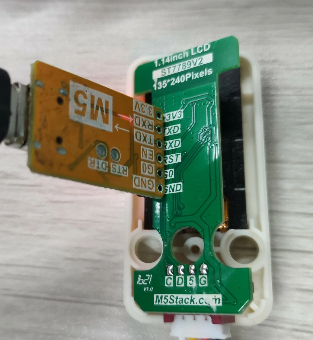
- Method 1. Use ESP32-Downloader to update firmware
Go to the resource page to download M5Burner Disassemble the Unit LCD enclosure and update the firmware using a USB Downloader.
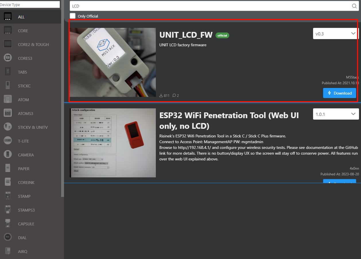
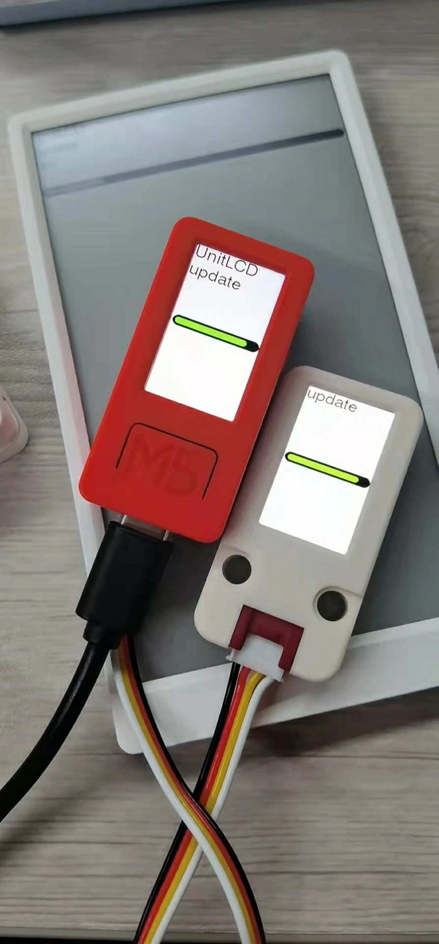
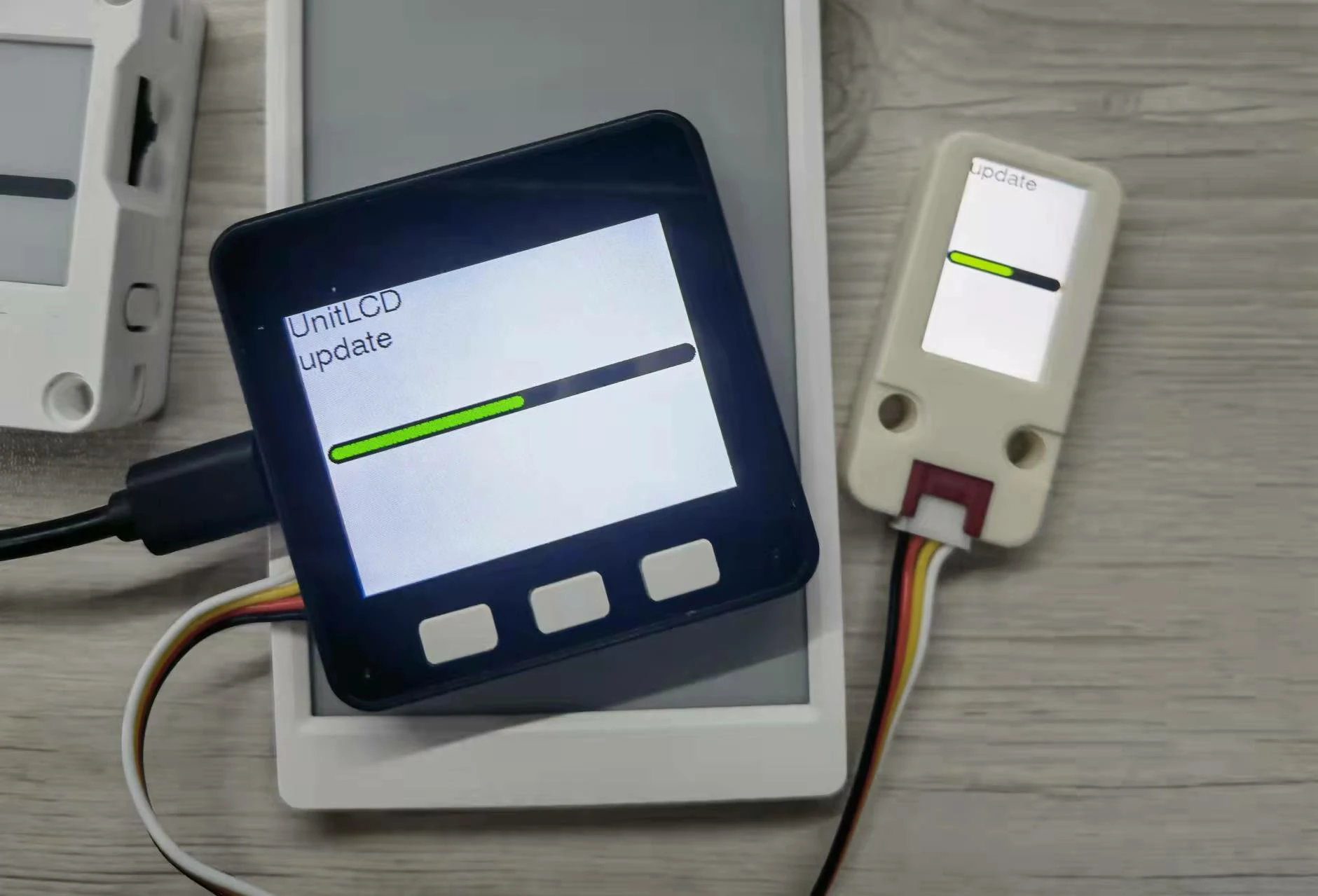
- Method 2. Update via I2C communication
Compile the above Github source code or go to the resource page to download M5Burner Flash the UNIT_LCD_FW firmware to any controller such as M5Core1/Core2/M5StickC/CPlus/ATOM/Paper. Connect Unit LCD to the I2C port using wires and the update will start automatically.
UiFlow1
UiFlow2
Video
- UiFlow2 Unit LCD