

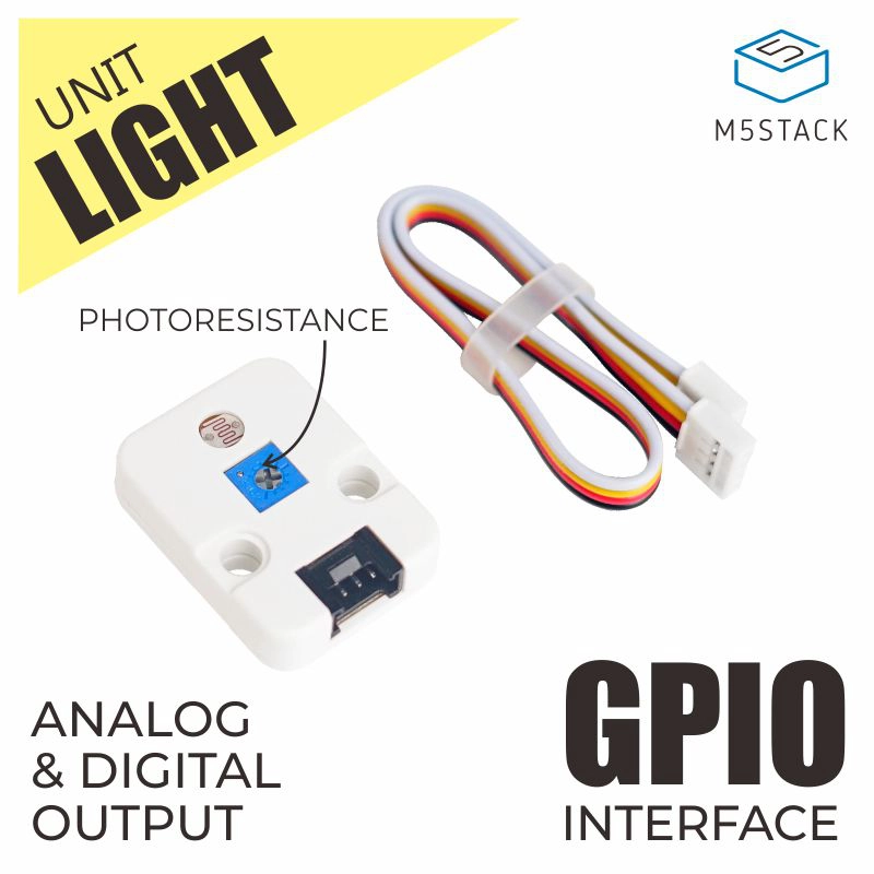
Unit Light
SKU:U021
Description
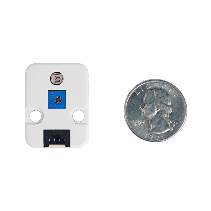
Unit Light is a light intensity detection sensor. It integrates a photoresistor and a 10K adjustable resistor, capable of detecting light intensity and setting a light intensity threshold. The resistance of the photoresistor decreases as the incident light intensity increases, thus detecting the change in voltage, and obtaining light intensity data through AD conversion. To achieve more accurate light intensity measurements, this Unit also adopts the LM393 dual differential comparator, used to compare the differential voltage between the photoresistor and the varistor.
Features
- Differential voltage design
- Analog and digital output
- Development Platform: Arduino, UIFlow
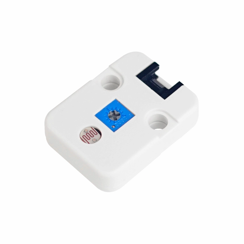
- 2 x LEGO compatible holes
Includes
- 1 x Unit Light
- 1 x HY2.0-4P Grove Cable (20cm)
Applications
- Light-controlled switch
- Solar yard lamp
- Infrared surveillance camera
Specifications
| Specification | Parameter |
|---|---|
| Adjustable Resistor | 10K |
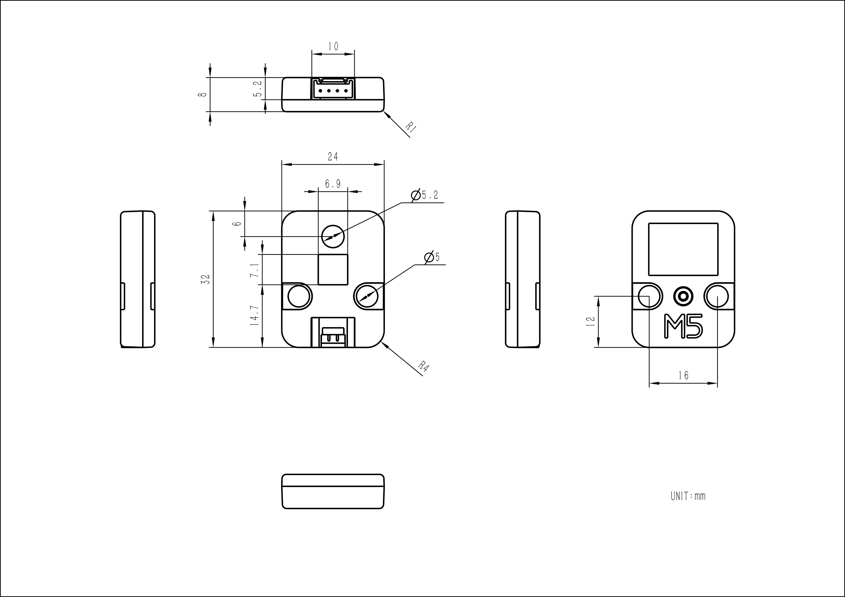
| Product Size | 32.0 x 24.0 x 8.0mm |
| Product Weight | 4.6g |
| Package Size | 138.0 x 93.0 x 9.0mm |
| Gross Weight | 10.0g |
Schematics
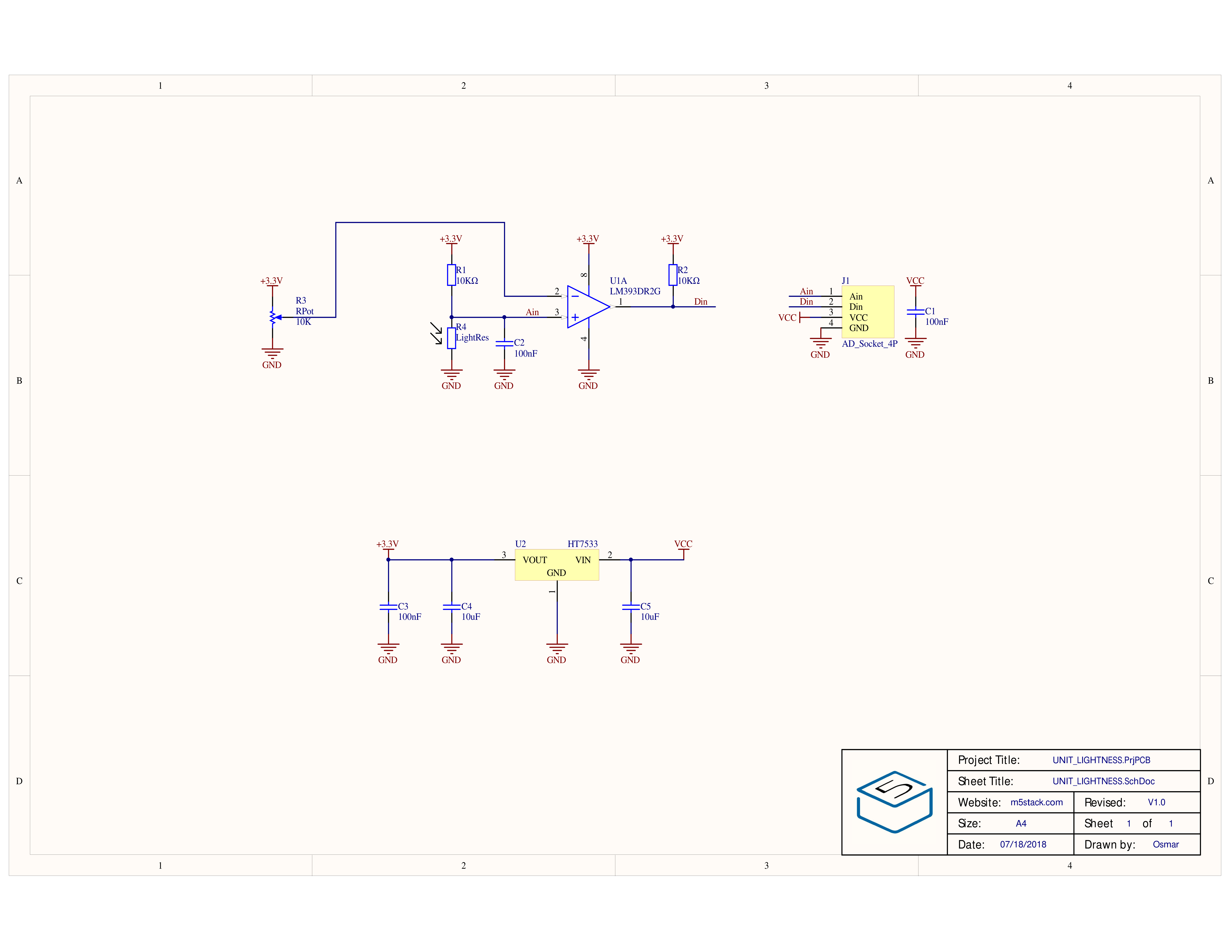
1/1
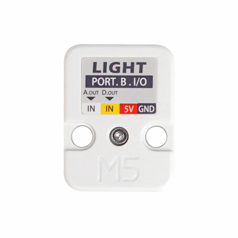
PinMap
Unit Light
| HY2.0-4P | Black | Red | Yellow | White |
|---|---|---|---|---|
| PORT.B | GND | 5V | Digital Output | Analog Output |
Model Size
Softwares
Arduino
UiFlow2
Easyloader
| Easyloader | Download | Note |
|---|---|---|
| Unit Light Test Example Easyloader | download | / |