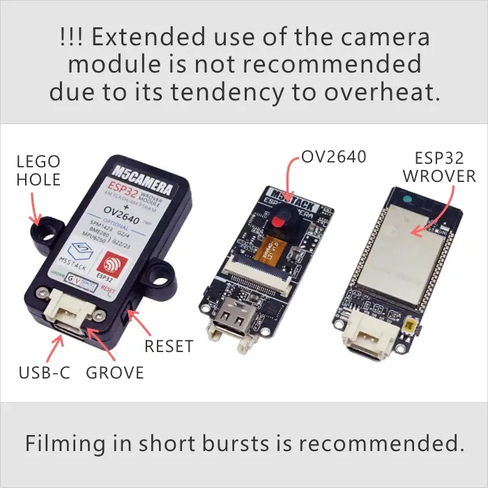
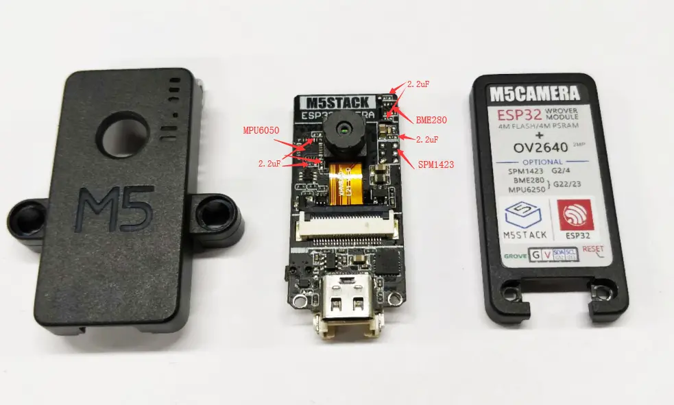
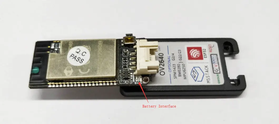
M5Camera is an image recognition development board that integrates an ESP32 (4M Flash + 520K RAM + 4M PSRAM) chip and a 2MP camera (OV2640). It supports Wi-Fi image transmission and USB port debugging.
Features
Designed based on ESP32
Wi-Fi image transmission
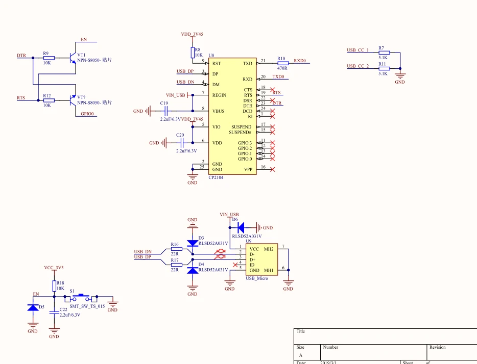
CP2104 USB TTL
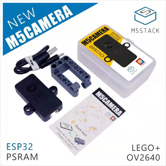
Includes
1 x M5Camera
4 x LEGO Adapter
1 x USB Type-C Cable (20cm)
Specifications
Specification
Parameter
Flash
4M
PSRAM
4MB Quad
Image Sensor
OV2640
Max Resolution
2MP
Output Format
YUV (422/420) /YCbCr422, 8-bit compressed data, RGB565/555, 8-/10-bit Raw RGB data
FOV
65°
Product Size
40.0 x 48.0 x 11.0mm
Product Weight
17.0g
Package Size
75.0 x 45.0 x 30.0mm
Gross Weight
41.0g
Learn
Hardware comes with pre-installed firmware, developed via ESP-IDF programming, running a Wi-Fi camera application. The default program outputs an image size of 600 x 800, and you can optimize the program to output a larger size.
How is this program used?
Turn on your phone’s Wi-Fi, scan and connect to an AP hotspot whose name starts with "m5stack-".
Open the phone browser, visit 192.168.4.1, and enter the monitoring page to get real-time video feed.
The video frame rate is about 5-6 frames per second.
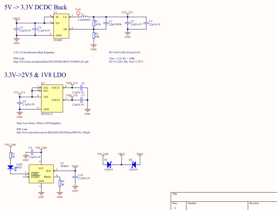
Schematics
Power Circuit
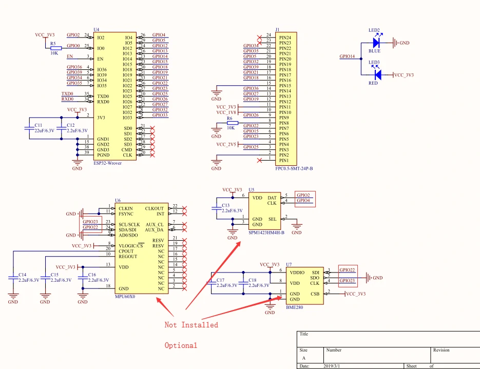
Chip Peripheral Circuit
USB to Serial Circuit
PinMap
Camera Driver Chip OV2640 Interface
Interface
Camera Pin
M5Camera
SCCB Clock
SIOC
G23
SCCB Data
SIOD
G22
System Clock
XCLK
G27
Vertical Sync
VSYNC
G25
Horizontal Reference
HREF
G26
Pixel Clock
PCLK
G21
Pixel Data Bit 0
D2
G32
Pixel Data Bit 1
D3
G35
Pixel Data Bit 2
D4
G34
Pixel Data Bit 3
D5
G5
Pixel Data Bit 4
D6
G39
Pixel Data Bit 5
D7
G18
Pixel Data Bit 6
D8
G36
Pixel Data Bit 7
D9
G19
Camera Reset
RESET
G15
Camera Power Down
PWDN
/
Power Supply 3.3V
3V3
3V3
Ground
GND
GND
The PIN8 (PDWN) pin of the OV2640 chip is an enable pin. In this board, it is enabled by connecting to ground via a 12KΩ pull-down resistor, entering working mode. When the PIN8 (PDWN) pin is pulled high, it will enter Camera Power Down mode.
HY2.0-4P Interface
HY2.0-4P
M5Camera
SCL
IO13
SDA
IO4
5V
5V
GND
GND
LED Interface
LED
M5Camera
LED_Pin
IO14
The following are PCB reserved interfaces, with components not actually soldered.