Home Assistant
Home Assistant OS
Kit
Unit VMeter Home Assistant Integration
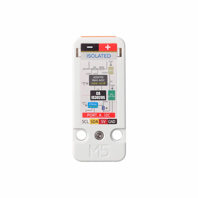
Unit VMeter is a voltage sensor for real-time voltage monitoring. It uses a 16-bit ADC converter ADS1115 internally and communicates over I2C (0x49).
Get the latest ADS1115 configuration from ESPHome
Configure the sensor
You need to enable the I²C component in your ESPHome configuration:
# Example configuration entry for ESP32
i2c:
  sda: GPIOXX
  scl: GPIOXX
scan: trueThe GPIO pins here will vary depending on the host device used. For example, when using Atom Lite as the host:
# I2C Bus on Grove Port (HY2.0-4P)
i2c:
  sda: GPIO26
scl: GPIO32Unit VMeter configuration example
- First, configure the base component ADS1115
ads1115:
- address: 0x49
sensor:
- platform: ads1115
multiplexer: "A0_A1"
gain: 1.024
sample_rate: 128
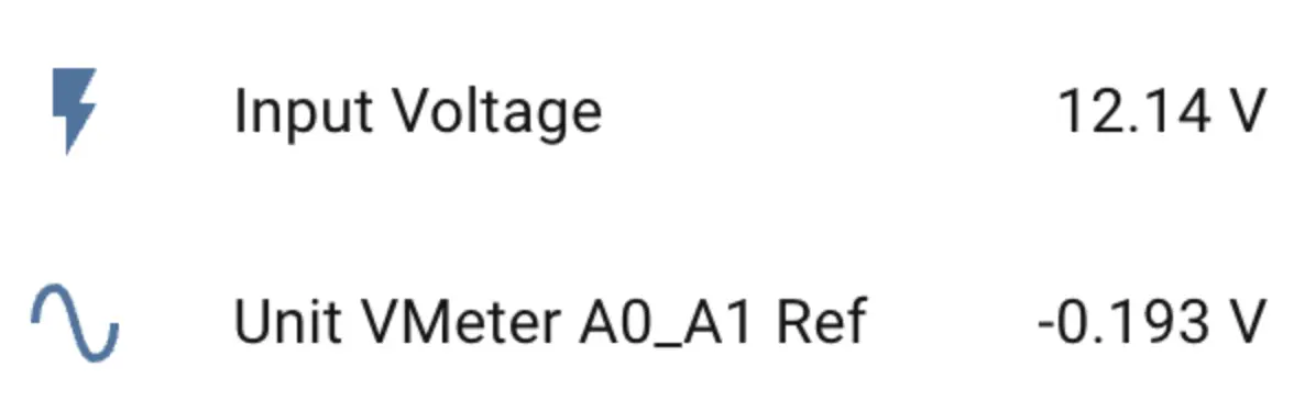
name: "Unit VMeter A0_A1 Ref"
id: diff
update_interval: 10sAIN0 and AIN1 channels, so you can use up to 3 multiplexer options: "A0_A1", "A0_GND", "A1_GND"; for voltage measurement this configuration uses only A0_A1.- Configure EEPROM to read calibration parameters and create custom data using a
Templatesensor
i2c_device:
  id: eeprom
  address: 0x53

sensor:
  # Previous ads1115 declarations
  ...
  - platform: template
    name: "Input Voltage"
    id: input_volt
    unit_of_measurement: "V"
    icon: "mdi:flash"
    accuracy_decimals: 2
    update_interval: 10s
    lambda: |-

      float d = id(diff).state;

      if (isnan(d)) return NAN;

      const float PRESSURE_COEFF = 0.015918958f;

      // Remember to change the 'EEPROM_REG' if you changed the 'gain'
      const uint8_t EEPROM_REG = 0xE8;

      uint8_t calib[8];
      uint16_t hope, actual;

      // Read EEPROM
      if ( id(eeprom).read_register(EEPROM_REG, calib, 8) != i2c::ERROR_OK ) {
        ESP_LOGD("vmeter.sensor", "Failed to read from EEPROM..");
        return NAN;
      }

      uint8_t xor_result = 0x00;

      for (uint8_t i = 0; i < 5; i++) {
          xor_result ^= calib[i];
      }

      if (xor_result != calib[5]) {
          return NAN;
      }

      hope   = (calib[1] << 8) | calib[2];
      actual = (calib[3] << 8) | calib[4];

      float calibration_ratio = (float)hope / actual;

      ESP_LOGD("vmeter.sensor", "Factory calibration factor: %f", calibration_ratio);

      float vin = - d / PRESSURE_COEFF;
      vin = vin * calibration_ratio;

return vin;When reading the EEPROM, you need to change the EEPROM_REG read address in the lambda expression according to the gain value set for ADS1115:
// In lambda expression
// remember to change the 'EEPROM_REG' if you changed the 'gain'
// for an example, when 'gain' is 1.024
const uint8_t EEPROM_REG = 0xE8;| ADS1115 Gain | EEPROM Data Register | Max Input Voltage (theory) |
|---|---|---|
| 6.144 | 0xD0 | - |
| 4.096 | 0xD8 | - |
| 2.048 | 0xE0 | - |
| 1.024 | 0xE8 | 64 V |
| 0.512 | 0xF0 | 32 V |
| 0.256 | 0xF8 | 16 V |
Recommended gain values are 0.256, 0.512 and 1.024; among them, for voltages below 16V resolution is 1mV, for voltages above 16V resolution is 7.9mV. Choose the appropriate gain value and the corresponding calibration parameters read from EEPROM according to the voltage under test. For accurate data, only one of AIN0 or AIN1 can be measured; do not connect both channels to voltage inputs.
Add the sensor to Home Assistant
After adding it to the Dashboard, you can view the sensor data in Home Assistant