
Dial v1.1
SKU:K130-V11




Description
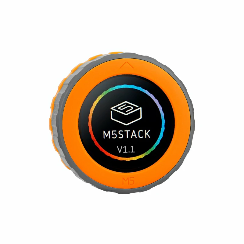
Dial v1.1 is a high-performance, multifunctional embedded development board that has been fully upgraded from the original Dial product. The new version features the Stamp-S3A as the main controller, further enhancing system processing power and stability. Additionally, the core module antenna and buttons have been optimized to effectively improve wireless communication performance and user interaction experience. The product is equipped with a 1.28-inch round TFT touch screen and a high-precision rotary encoder, and includes an RFID detection module, RTC circuit, onboard buzzer, and under-screen buttons to enable device interaction and wake-up alerts. The power supply solution supports DC 6~36V wide voltage input and includes a lithium battery interface and charging circuit to meet diverse application needs. Furthermore, the reserved PORT.A and PORT.B interfaces facilitate the expansion of I2C and GPIO devices. This product is applicable in smart home control, IoT applications, smart wearables, access control systems, industrial control, and educational maker projects.
Tutorial

Features
- Round TFT touch screen
- Stamp-S3A as the main controller
- Rotary encoder
- RFID detection module
- Wide voltage input
- Interface expansion: Reserved PORT.A and PORT.B interfaces
- Development Platform
- UiFlow2
- Arduino IDE
- ESP-IDF
- PlatformIO
Includes
- 1 x Dial V1.1
- 1 x L-shaped 1.5mm hex wrench (compatible with M2 screws)
- 1 x 2.54-2P terminal
Applications
- Smart home control
- IoT projects
- Access control systems
- Industrial control
Specifications
| Specification | Parameter |
|---|---|
| SoC | ESP32-S3FN8 @ Xtensa® 32-bit LX7 dual-core processor, clock frequency 240MHz |
| USB | USB OTG, USB Serial/JTAG |
| Flash | 8MB |
| Wi-Fi | 2.4 GHz Wi-Fi |
| Wide Voltage Input Range | DC 6 ~ 36V |
| Screen Driver | GC9A01 1.28 Inch 240 x 240px |
| Touch Driver | FT3267 |
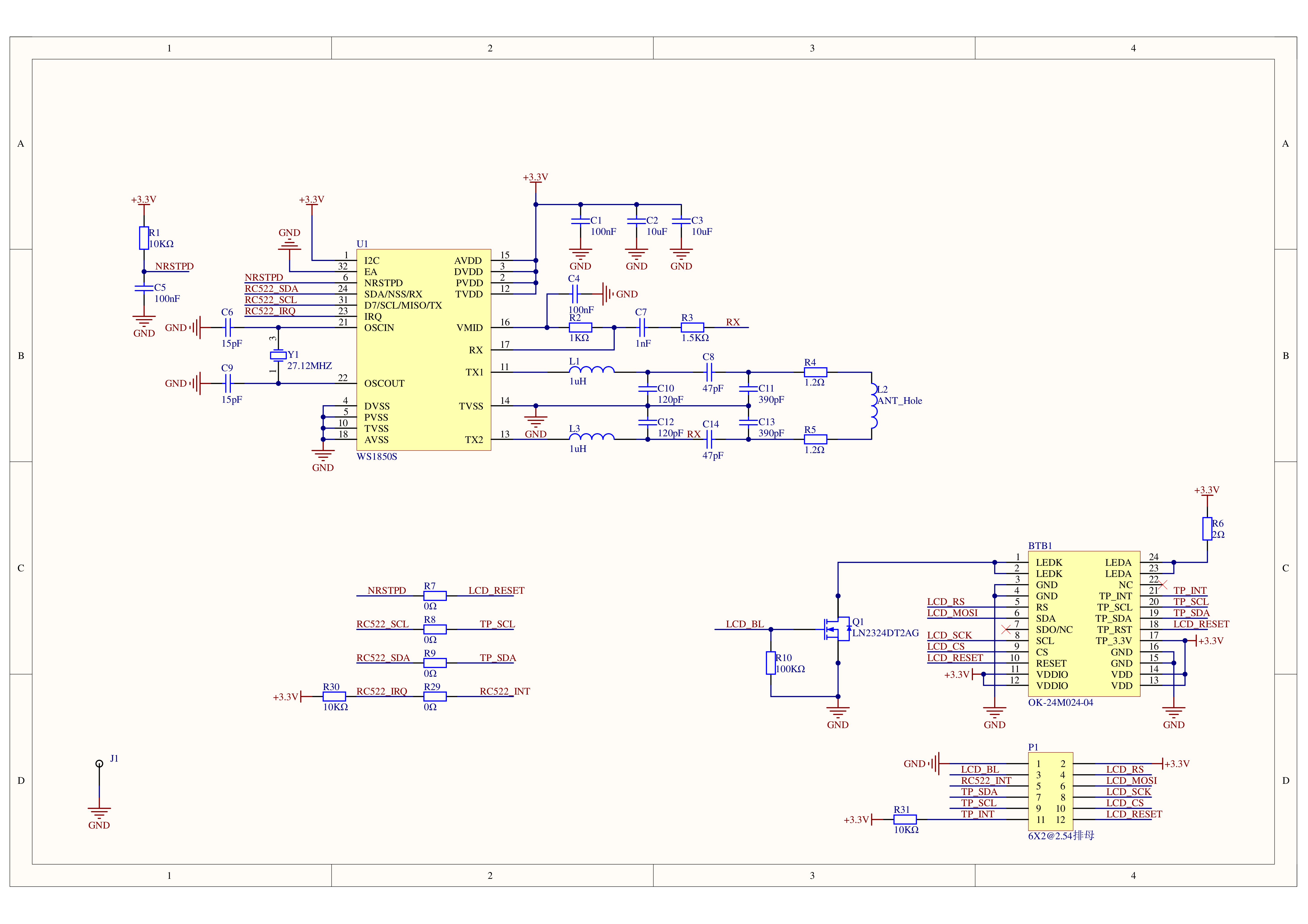
| RFID | WS1850S @ Tag operating frequency: 13.56 MHz, ISO/IEC 14443 Type A/Type B protocol |
| Encoder | Resolution: 16 positions, 64 pulses/rev |
| Buzzer | 80dB |
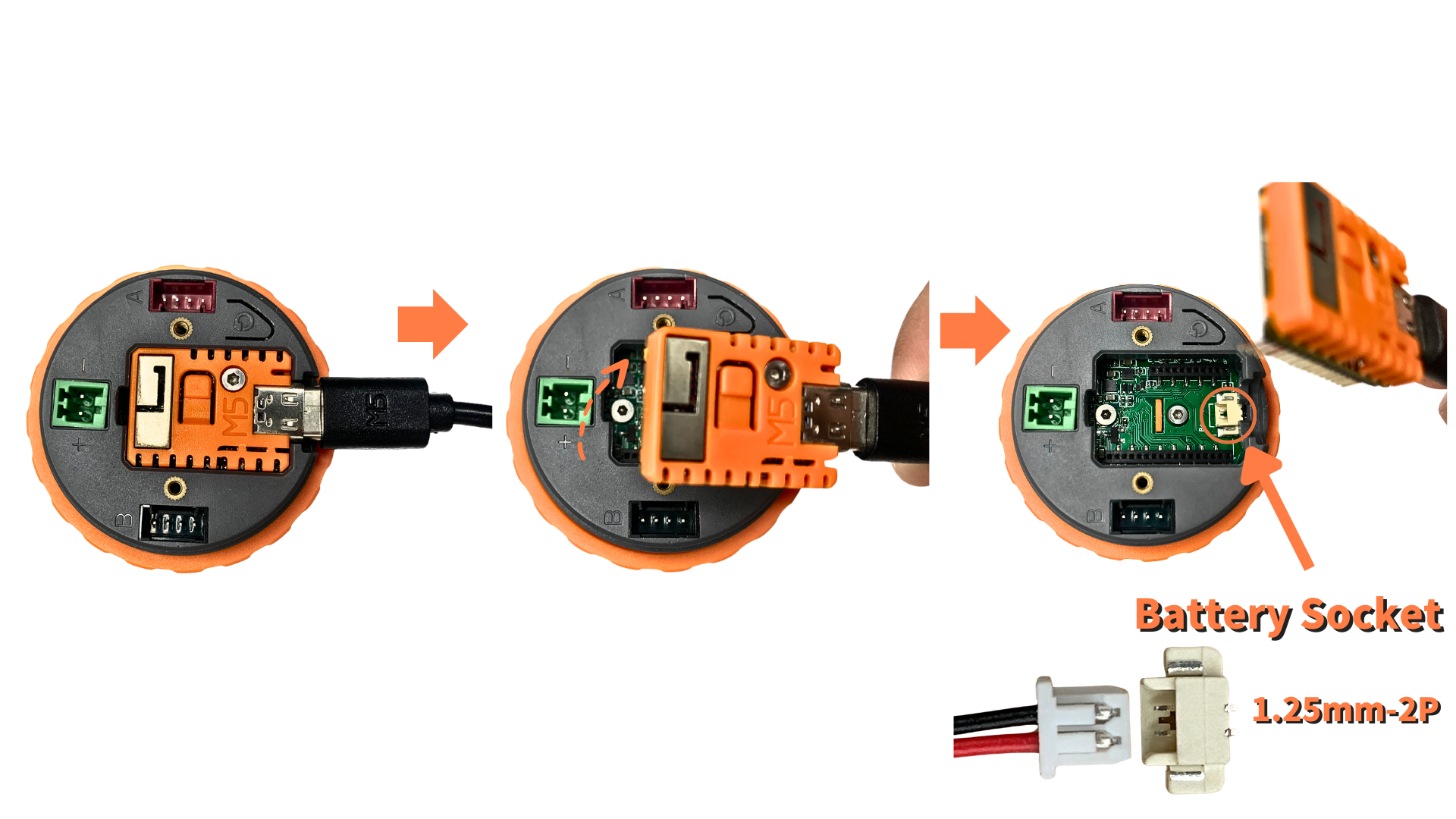
| Battery Socket Specification | 1.25mm-2P |
| Sleep Current | USB supply: DC 5V@6.84mA (LDO idle power consumption) Battery only: DC 4V@6uA |
| Operating Current | USB supply: DC 5V@88.19mA Battery only: DC 4V@100mA |
| Power Interface Specification | Model KF2EDGV-2.54-2P, straight pin design, 2.54mm pitch (2Pin), green |
| Operating Temperature | 0 ~ 40°C |
| Product Size | 51.0 x 51.0 x 32.3mm |
| Product Weight | 46.2g |
| Package Size | 71.9 x 71.9 x 57.4mm |
| Gross Weight | 61.0g |
Learn
Power On/Off
Power Off: Similarly, when there is no external USB power supply (battery only), the device can be turned off by pressing the RST button or by setting the HOLD (GPIO46) pin to low (0) in the program.
Download Mode
.gif)
RGB LED Power Supply
Dial v1.1 Lithium Battery Expansion Interface
RFID Card
If the size of the RFID tag is smaller than the outer dimensions of the Dial, it may not be recognized or may cause communication errors. It is recommended to use an RFID card in the standard bank card size.
Schematics
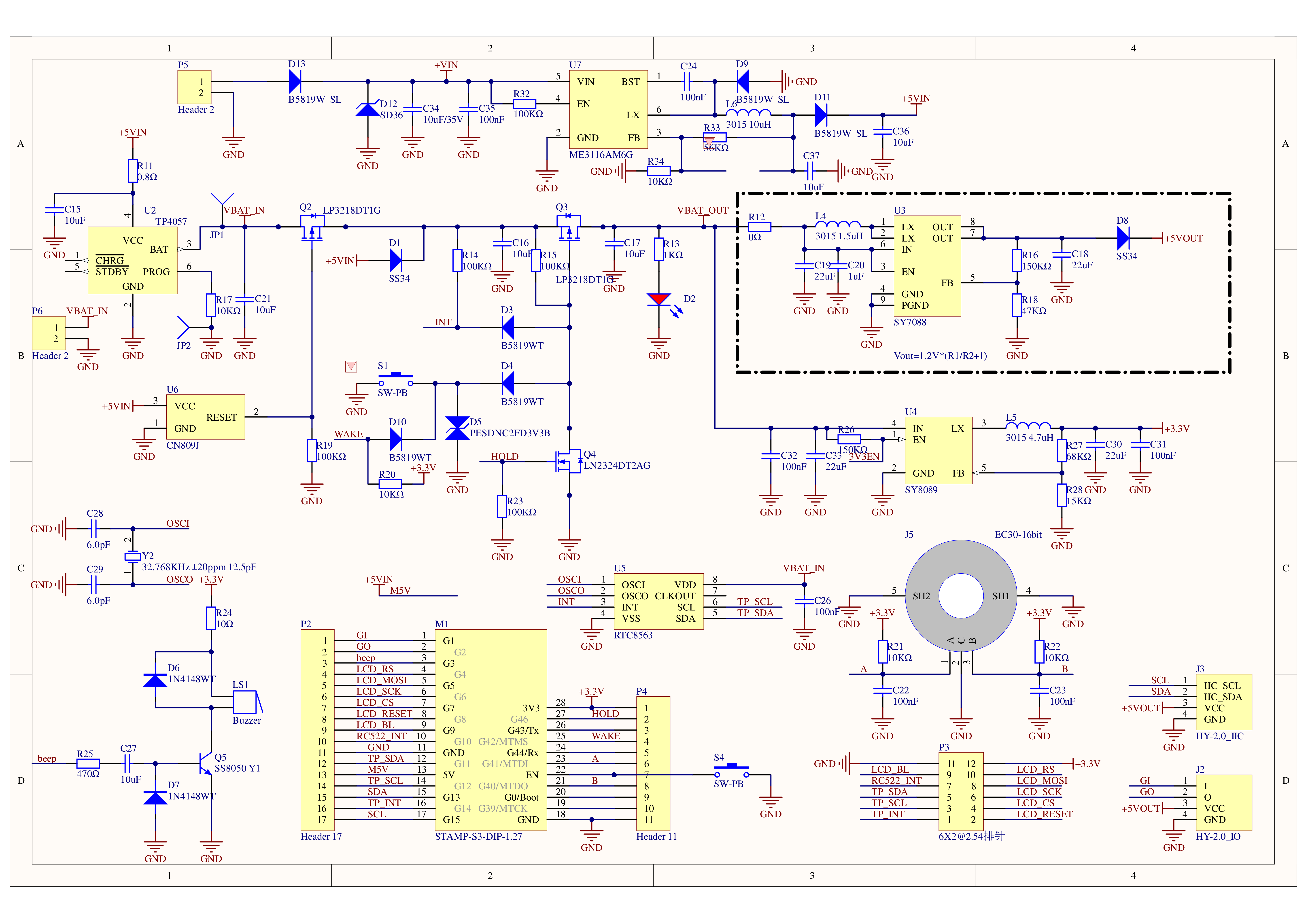
PinMap
I2C Sensor (RTC8563 & WS1850S)
| ESP32-S3 | G12 | G11 | G8 | G10 | G3 |
|---|---|---|---|---|---|
| RTC8563 | SCL | SDA | |||
| WS1850S(RFID) | SCL | SDA | RST | IRQ | |
| Buzzer | beep |
ENCODER
| ESP32-S3 | G40 | G41 | VCC | GND |
|---|---|---|---|---|
| ENCODER | B | A | 5V | GND |
Screen Driver (GC9A01-SPI) & Touch Driver
| ESP32-S3 | G4 | G5 | G6 | G7 | G8 | G9 | G11 | G12 | G14 |
|---|---|---|---|---|---|---|---|---|---|
| GC9A01 | LCD_RS | LCD_MOSI | LCD_SCK | LCD_CS | LCD_RESET | LCD_BL | |||
| FT3267 | TP_SDA | TP_SCL | TP_INT |
HY2.0-4P
| HY2.0-4P | Black | Red | Yellow | White |
|---|---|---|---|---|
| PORT.A | GND | 5V | G13 | G15 |
| PORT.B | GND | 5V | G2 | G1 |
Model Size
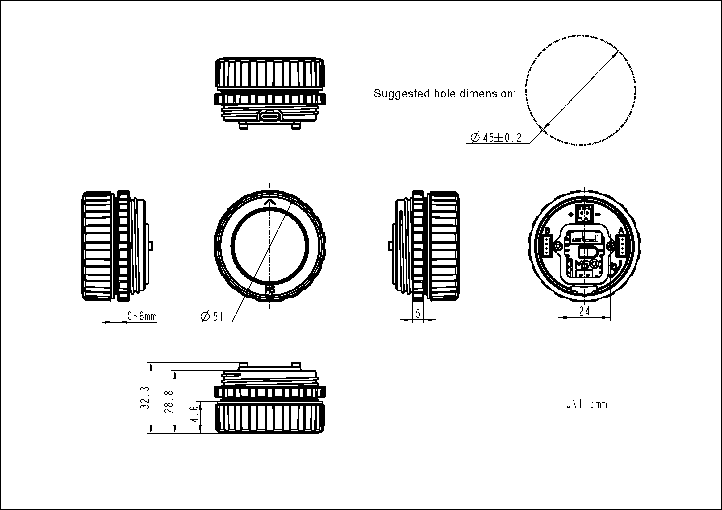
Structure
Datasheets
Softwares
Arduino
UiFlow2
Easyloader
| Easyloader | Download Link | Notes |
|---|---|---|
| Dial v1.1 User Demo Easyloader | download | / |
| Dial v1.1 Knob Panel Demo Easyloader | download | / |
ESP-IDF
Video
Product Comparison
| Comparison Item | Dial v1.1 | Dial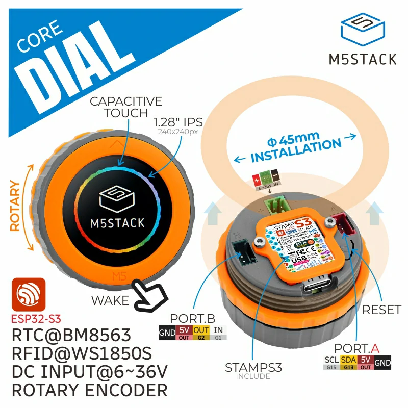 |
|---|---|---|
| Core Module | Stamp-S3A | StampS3 |
| Antenna Design | Optimized design, stronger signal | Standard design |
| Stamp-S3A module Boot button | Optimized button feel, buttons use 4.0 x 3.0 x 2.0mm specs | Button specs 2.6 x 1.6 x 0.55mm |
| Power Consumption | Optimized for lower power consumption | Standard design |