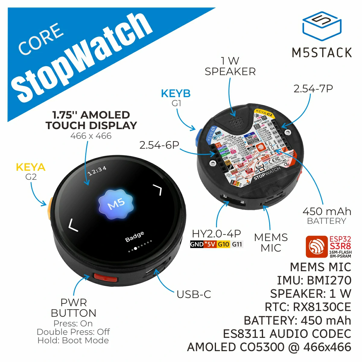
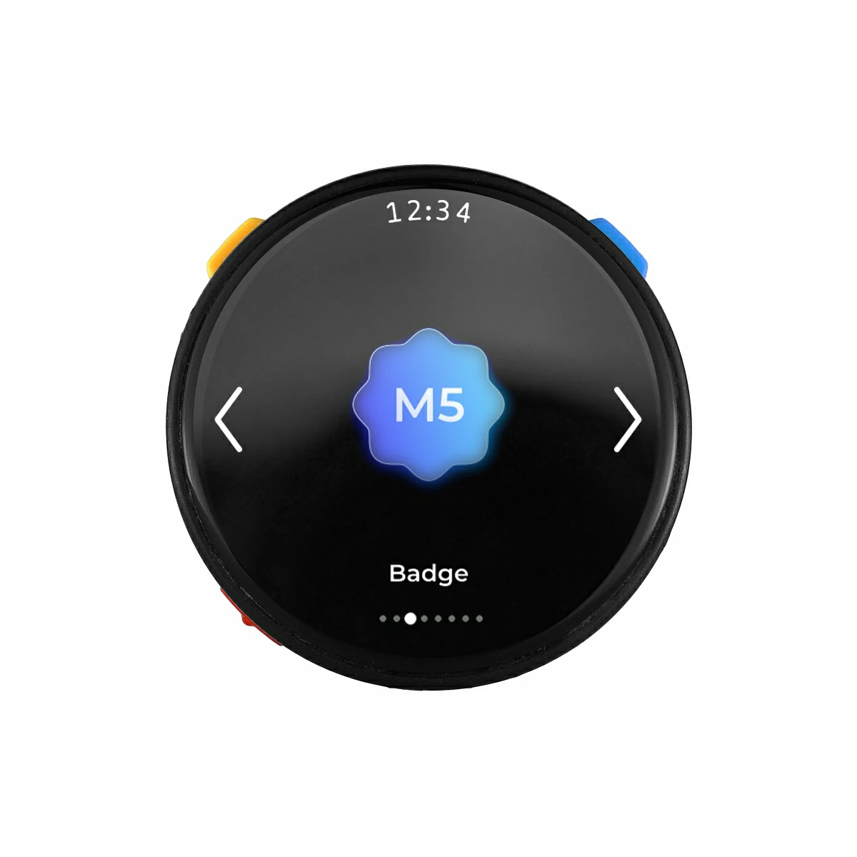
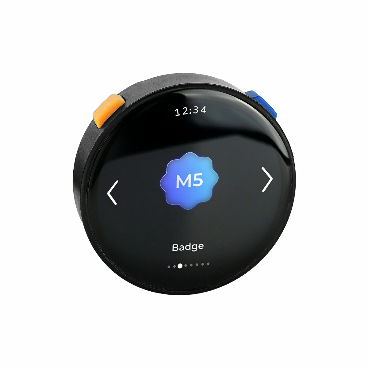
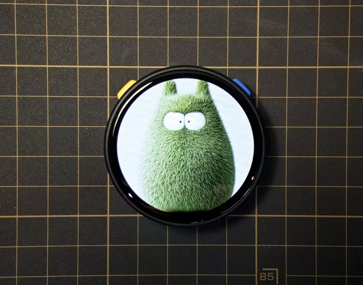
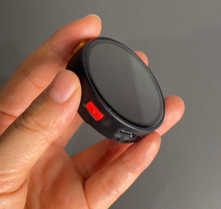
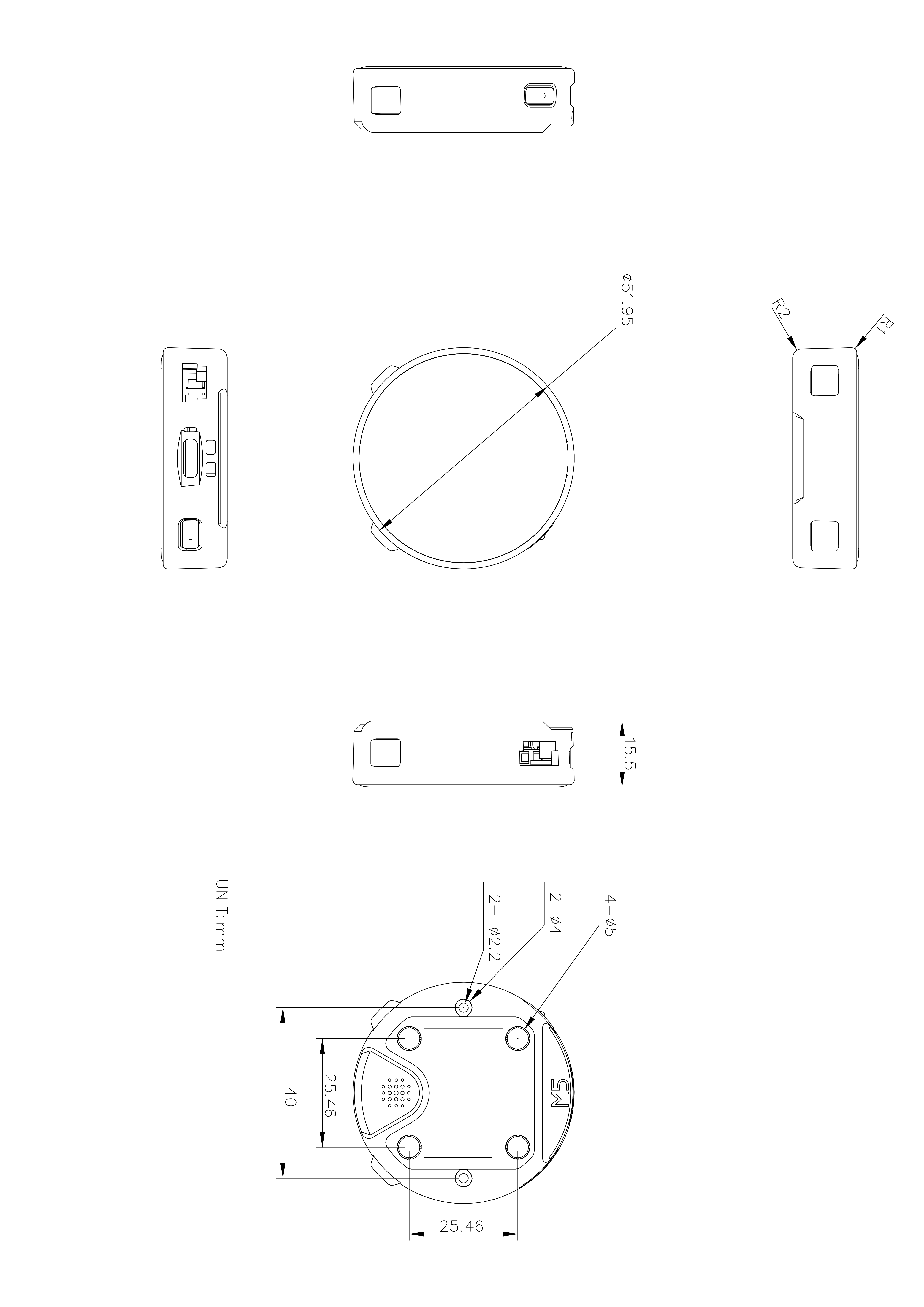
StopWatch is a round AMOLED touch development board designed for portable and interactive scenarios. It features an ESP32-S3R8 main controller with 16MB Flash and 8MB PSRAM, supporting 2.4GHz Wi-Fi wireless communication. The device integrates a 1.75" AMOLED touch round screen, programmable buttons, and vibration feedback for an intuitive human-machine interaction experience. It also features audio input/output, IMU attitude sensing, RTC timekeeping, and multiple expansion interfaces. Combined with the M5PM1 multi-level power management system and a 450mAh battery, it meets diverse development needs including portable smart control, wearable human-machine interaction, and lightweight IoT terminals.
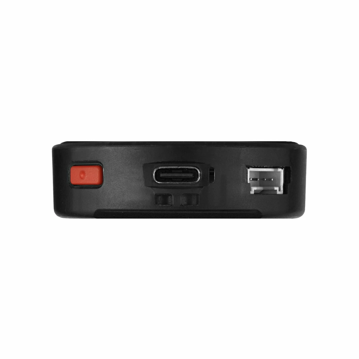
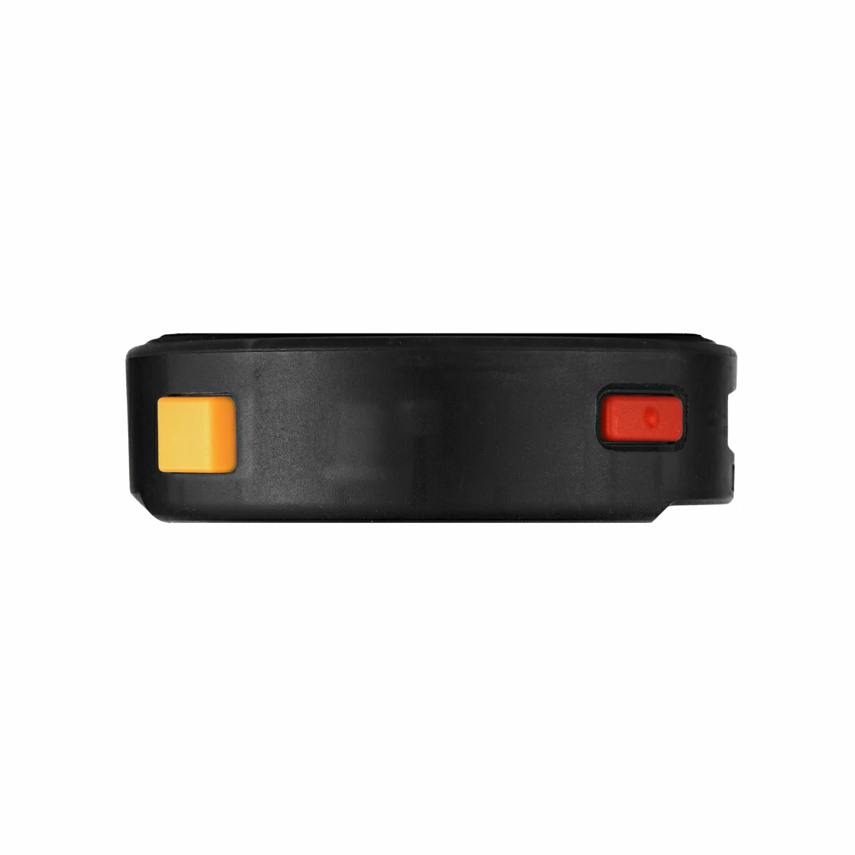
Power Off: Press the power button twice consecutively
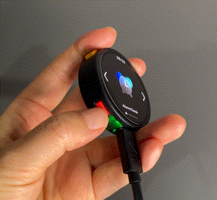
Download Mode
Long press the reset button (approximately 2 seconds) until the green LED lights up, then release. The device has entered download mode and is waiting for firmware flashing.
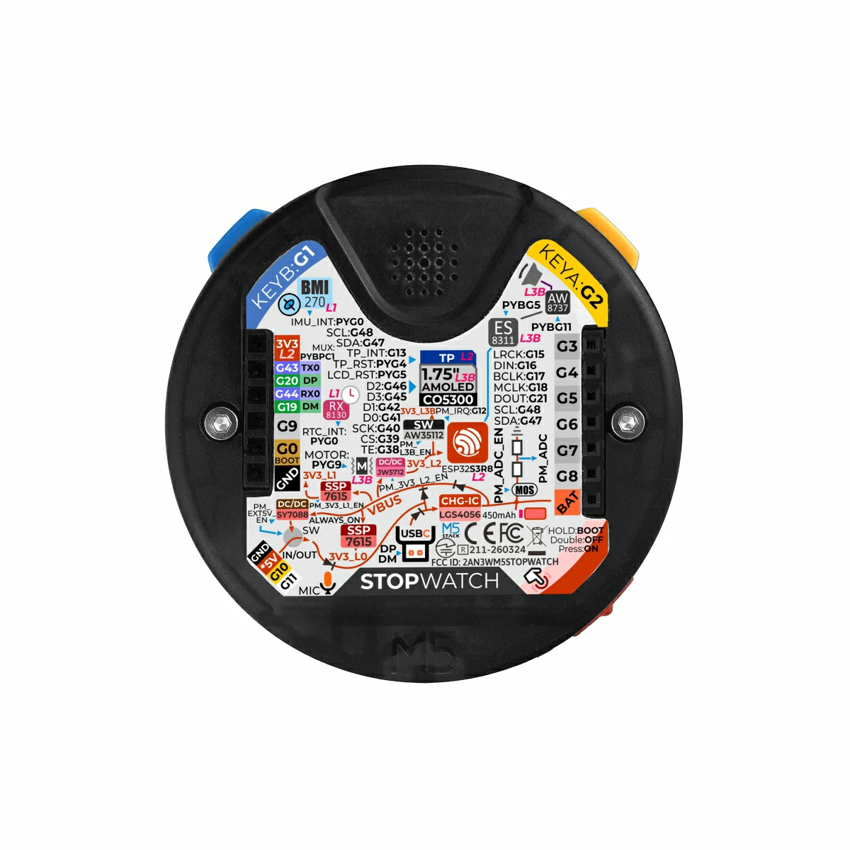
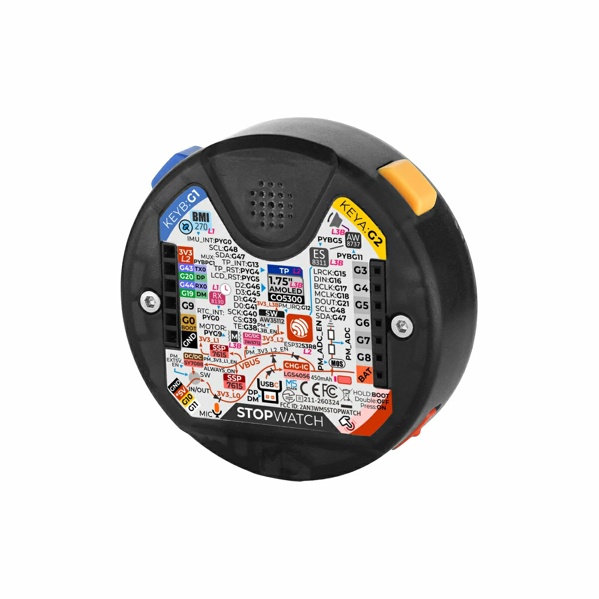
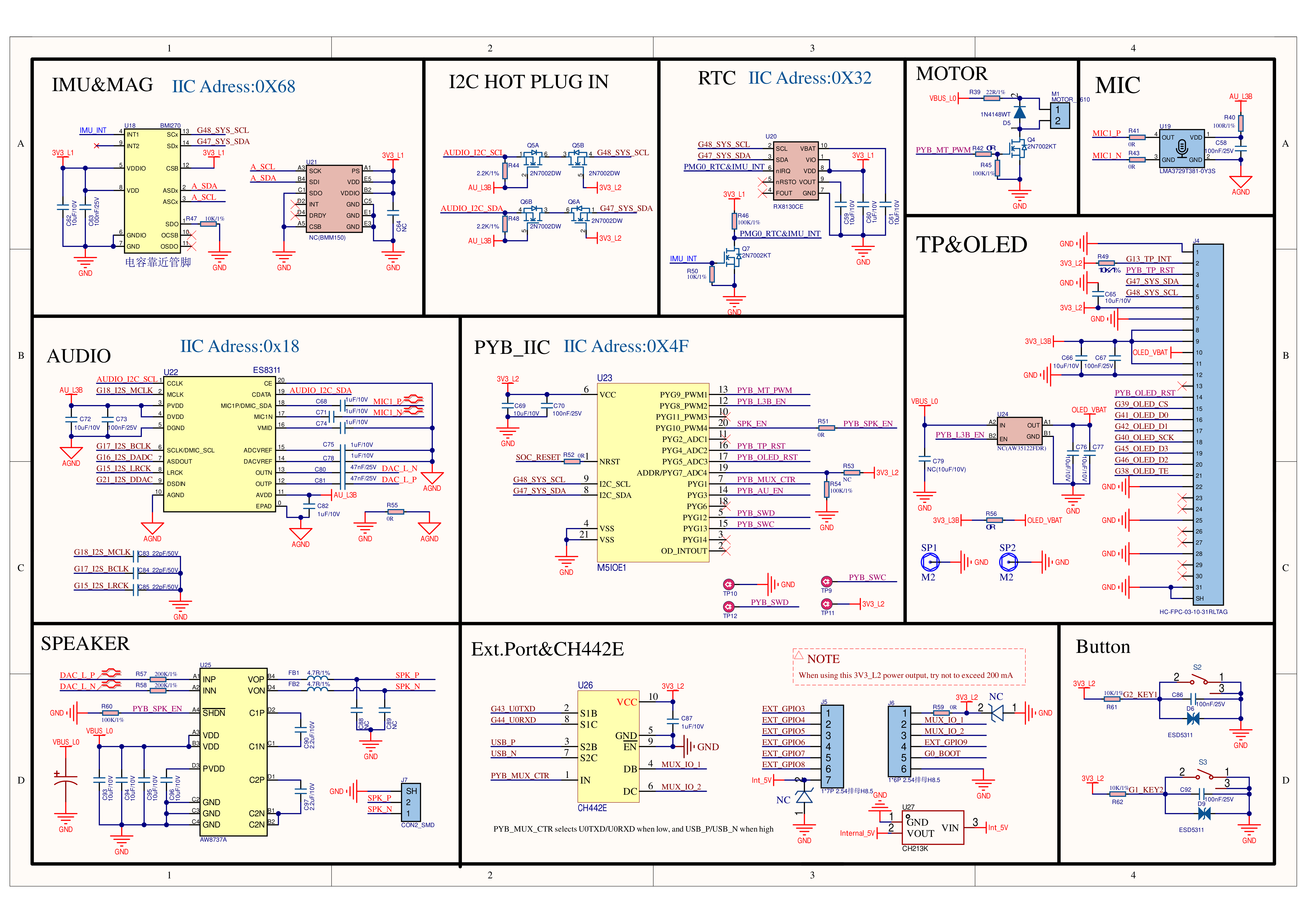
The display reset is controlled via PYG5 (PYB_OLED_RST) of the M5IOE1 expansion chip.
Touch
ESP32S3R8
G47
G48
G13
CST820B
SYS_SDA
SYS_SCL
TP_INT
The touch reset is controlled via PYG4 (PYB_TP_RST) of the M5IOE1 expansion chip.
Audio
ESP32S3R8
G48
G47
ES8311(0x18)
AUDIO_I2C_SCL
AUDIO_I2C_SDA
ESP32S3R8
G18
G17
G16
G15
G21
ES8311
I2S_MCLK
I2S_BCLK
I2S_ASDOUT
I2S_LRCK
I2S_DSDIN
The speaker amplifier (AW8737A) enable is controlled via PYG10(PYB_SPK_EN) of the M5IOE1 expansion chip, and the Audio L3B level power supply for audio peripherals is controlled via PYG3(PYB_AU_EN).
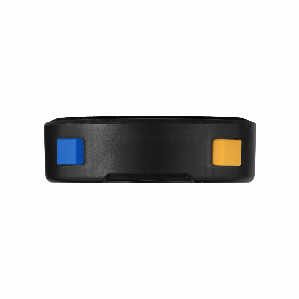
KEY
ESP32S3R8
G2
G1
KEY
KEYA (YELLOW)
KEYB (BLUE)
IMU & RTC
ESP32S3R8
G48
G47
BMI270(0x68)
SYS_SCL
SYS_SDA
RX8130CE(0x32)
SYS_SCL
SYS_SDA
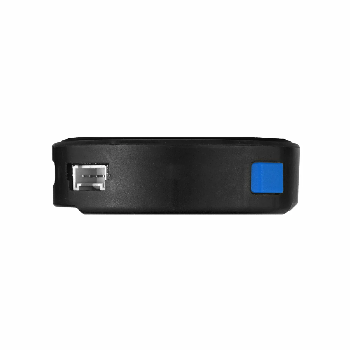
HY2.0-4P
HY2.0-4P
Black
Red
Yellow
White
PORT.A
GND
5V
G10
G11
EXT 2.54 Bus
FUNC
PIN
LEFT
RIGHT
PIN
FUNC
3V3_L2
1
2
G3
G43(UART0_TX) / G20(USB_DP)
MUX_IO_1
3
4
G4
G44(UART0_RX) / G19(USB_DM)
MUX_IO_2
5
6
G5
G9
7
8
G6
BOOT
G0
9
10
G7
GND
11
12
G8
/
13
14
BAT
The MUX_IO_1, MUX_IO_2 pin switching between USB / UART functions is controlled via PYG1(PYB_MUX_CTR) of the M5IOE1 expansion chip. The default function is UART.
PYG1_HAT_SW
EXT MUX_IO_1/2 FUNC
LOW
G43_U0TXD / G44_U0RXD
HIGH
USB_P / USB_N
M5PM1
ESP32S3R8
G48
G47
M5PM1
SYS_SCL
SYS_SDA
M5PM1
DCDC3V3_EN_PP
LDO3V3_EN_PP
BOOST5V_EN_PP
3V3_L2
PM_3V3_L2_EN
3V3_L1
PM_3V3_L1_EN
Grove
PM_EXT_5V_EN
M5PM1
PYG0
PYG2
PYG4
PYG3
PYG1
RTC & IMU
RTC_INT & IMU_INT
CHARGE
CHG_STAT
CHG_PROG
EXT 5VIN
PORT_INT
ESP32S3R8
G12_PY_IRQ
PYG0(RTC_INT & IMU_INT): Interrupt wake-up signal
PYG2(CHG_STAT): Charging status
PMG4(PORT_INT): External power wake-up signal
PYG1(G12_PY_IRQ): Interrupt signal connected to ESP32-S3
PMG3_CHG_PROG: Charging current control
PMG3_CHG_PROG
CHARGE CURRENT
LOW
425mA
HIGH
185mA (Default)
M5IOE1
ESP32S3R8
G48
G47
M5IOE1(0x4F)
SYS_SCL
SYS_SDA
M5IOE1
PYG1
PYG3
PYG9
PYG8
PYG10
PYG4
PYG5
Ext.Port Select
PYB_MUX_CTR
Audio L3B
PYB_AU_EN
Vibration Motor
PYB_MT_PWM
3V3_L3B
PYB_L3B_EN
Speaker AMP AW8737A
PYB_SPK_EN
Touch
PYB_TP_RST
AMOLED
PYB_OLED_RST
PYG1(PYB_MUX_CTR): Rear expansion interface MUX_IO_1/2 switching between USB / UART functions
PYG3(PYB_AU_EN): ES8311 power supply + MIC power supply