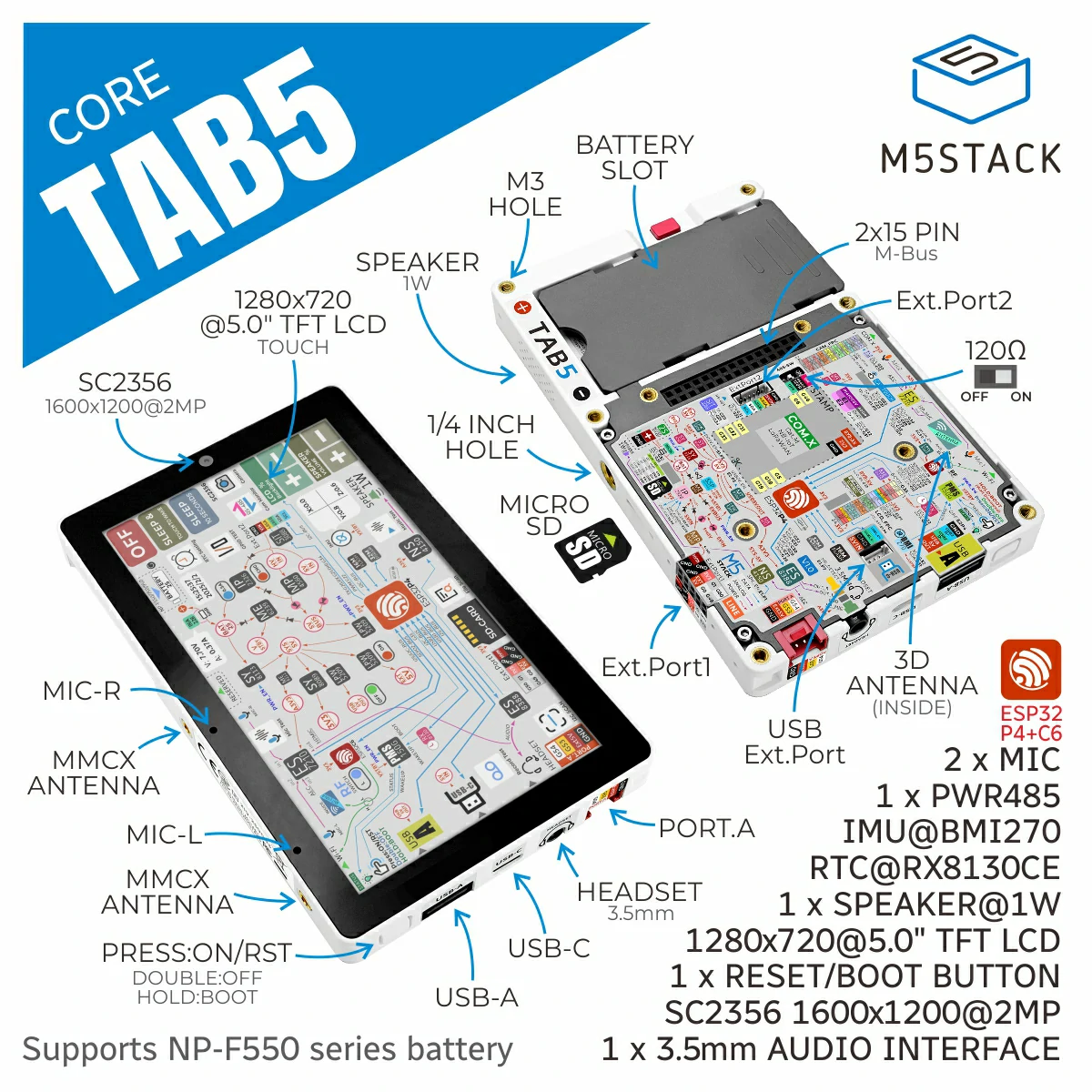
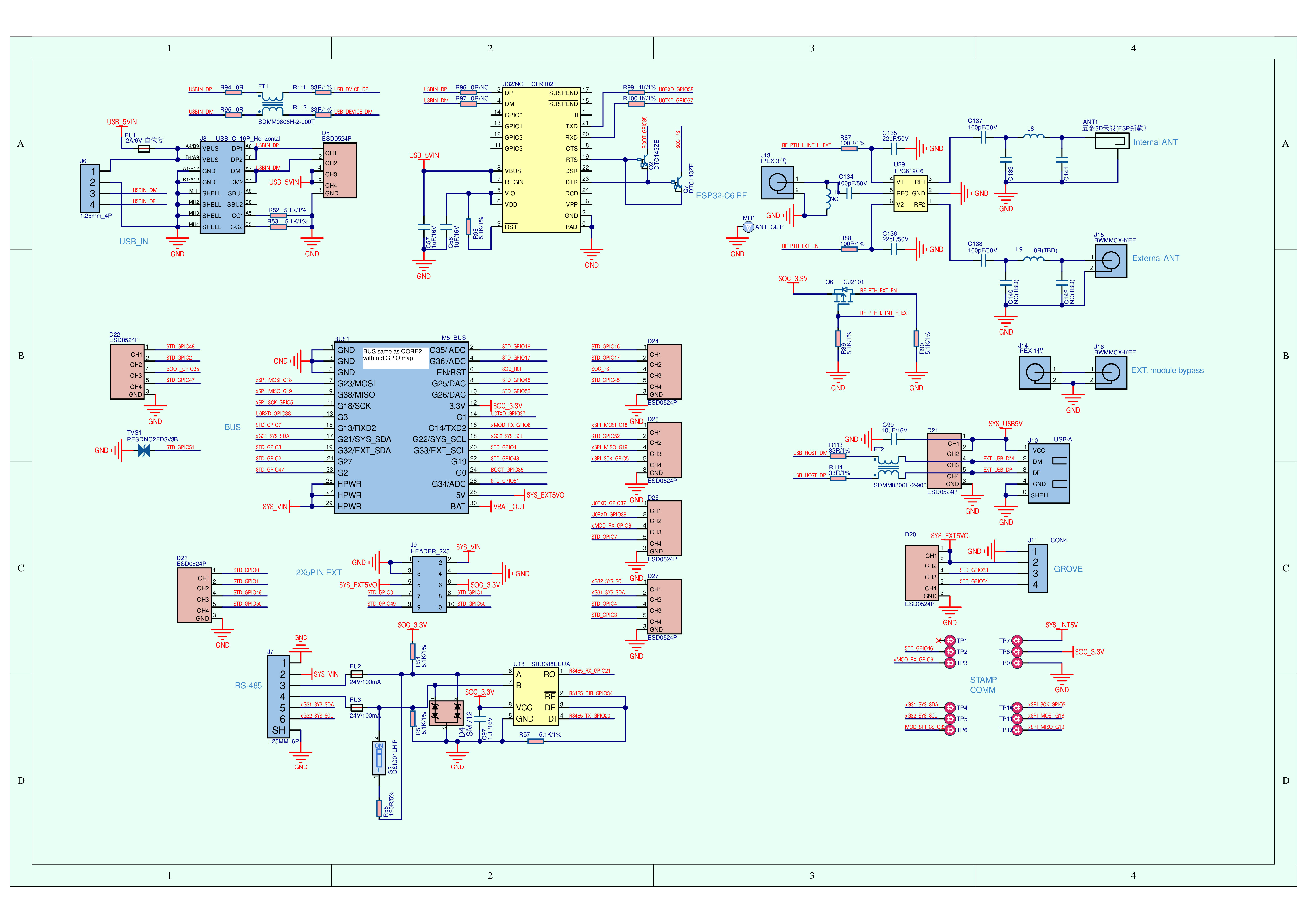
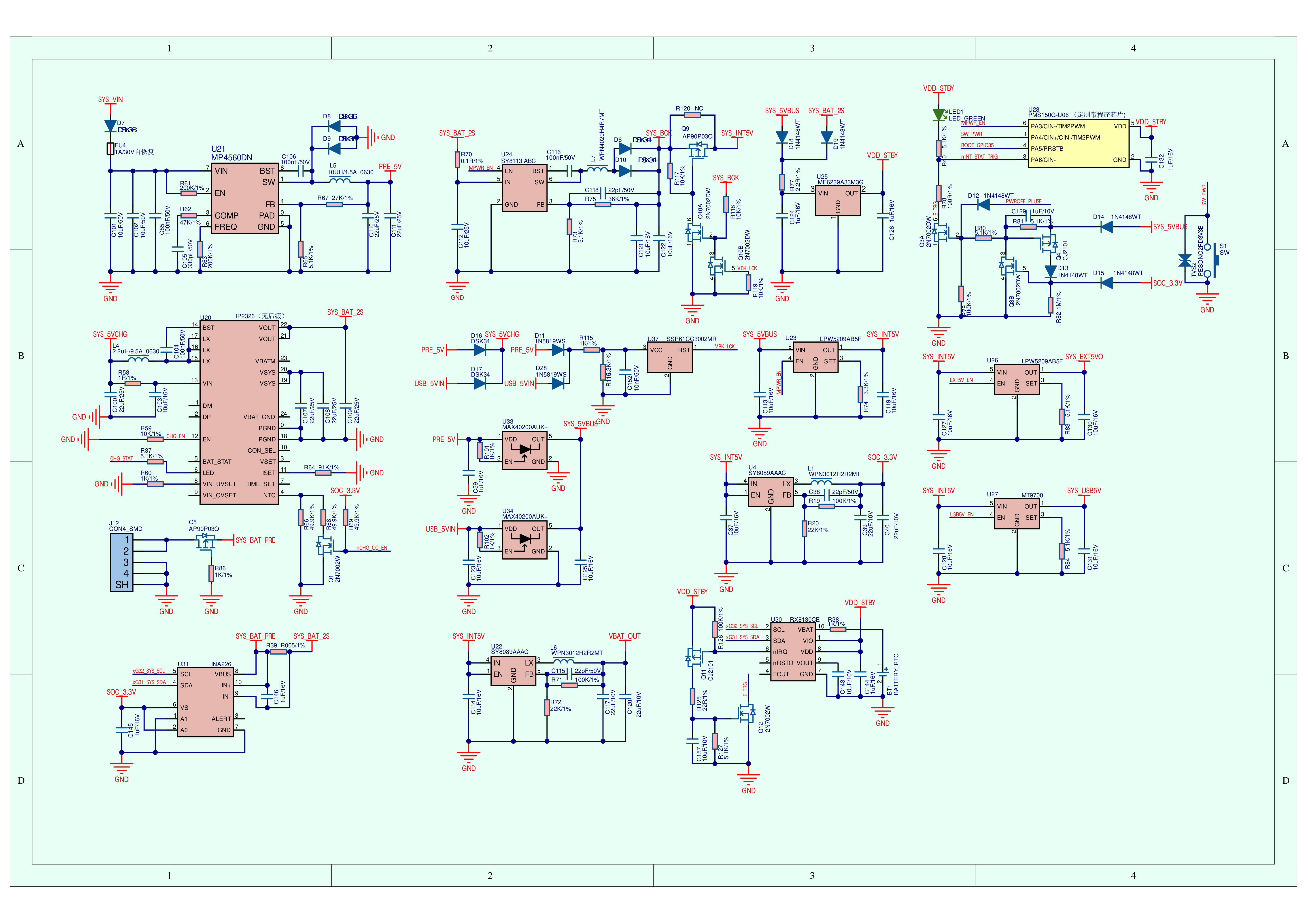
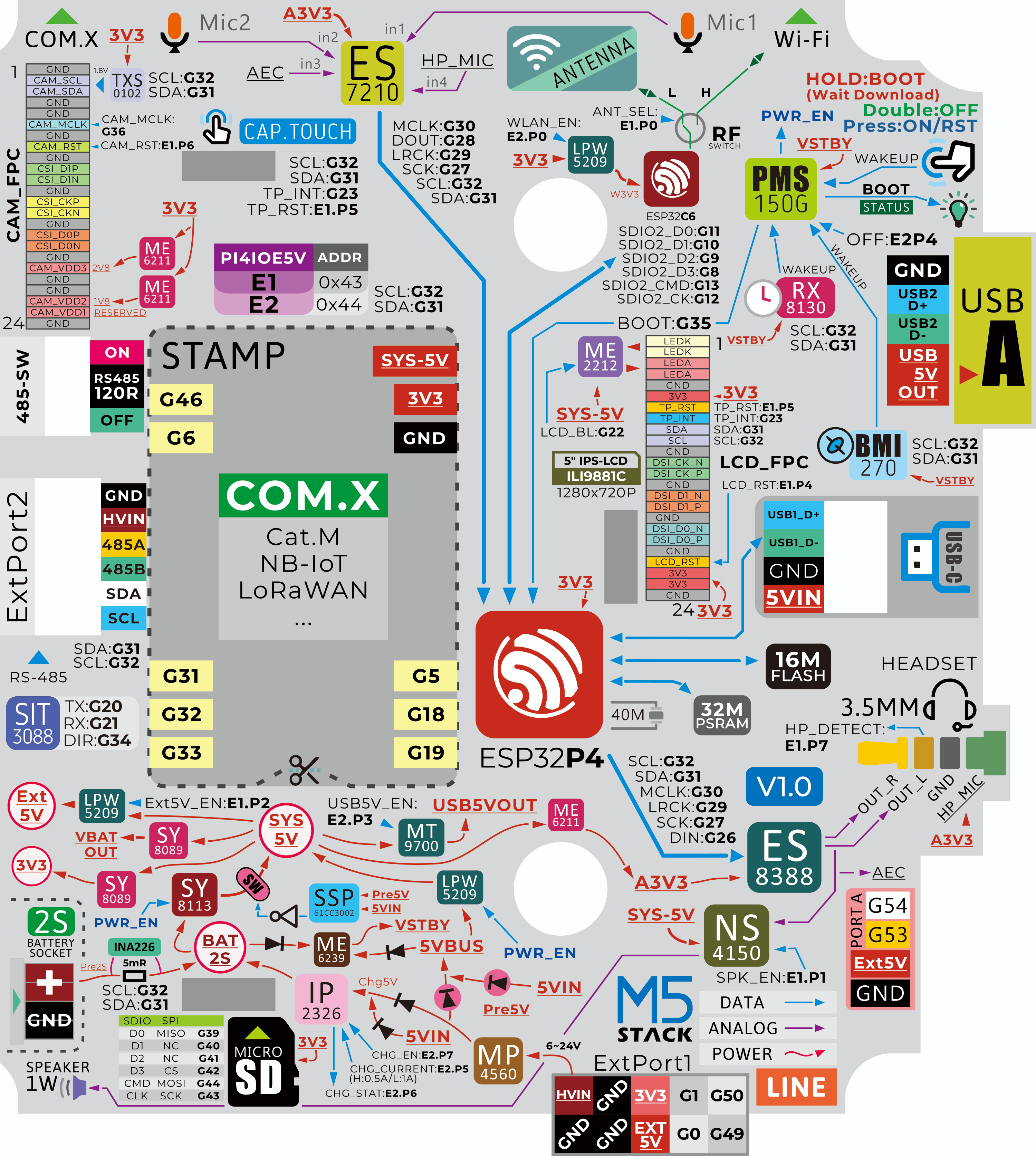
Tab5 is a highly expandable, portable smart-IoT terminal development device for developers, integrating a dual-core architecture and rich hardware resources. The main controller adopts the ESP32-P4 SoC based on the RISC-V architecture, with 16MB Flash and 32MB PSRAM. The wireless module uses the ESP32-C6-MINI-1U, supporting Wi-Fi 6. Its antenna system can freely switch between the built-in 3D antenna and an external MMCX antenna interface, flexibly adapting to various deployment environments to ensure data throughput and low-latency control.
In terms of visual and interactive experience, the Tab5 is equipped with a 5″ 1280×720 IPS touchscreen featuring an MIPI‑DSI interface, delivering a smooth and responsive touch interaction. It also comes with an SC2356 2MP camera (1600×1200) that uses an MIPI‑CSI interface, enabling HD video recording, image processing, and edge AI applications such as facial recognition and object tracking.
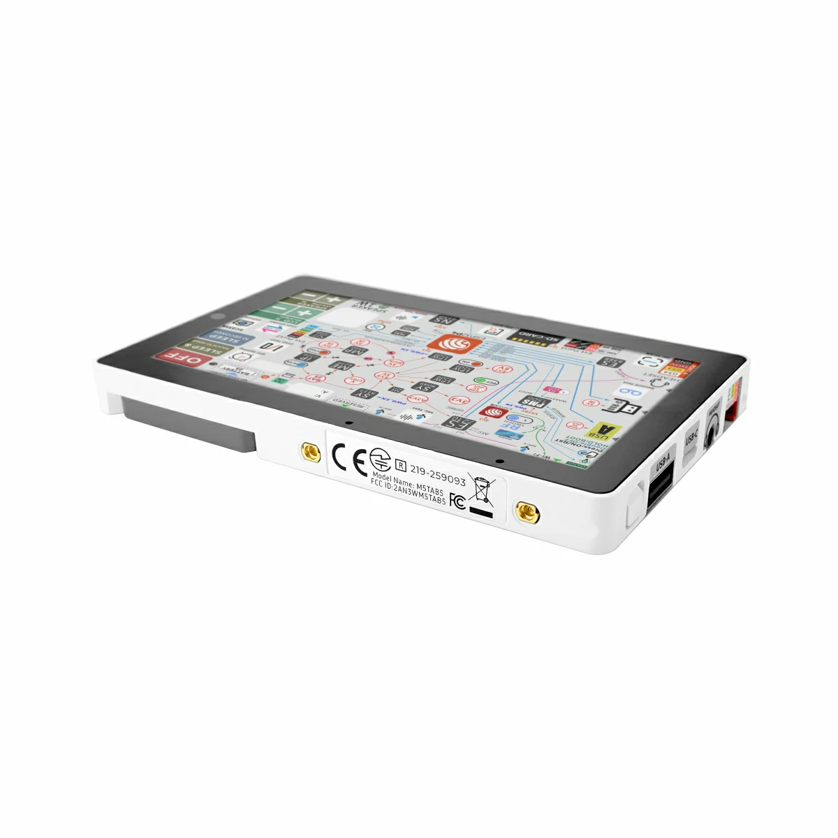
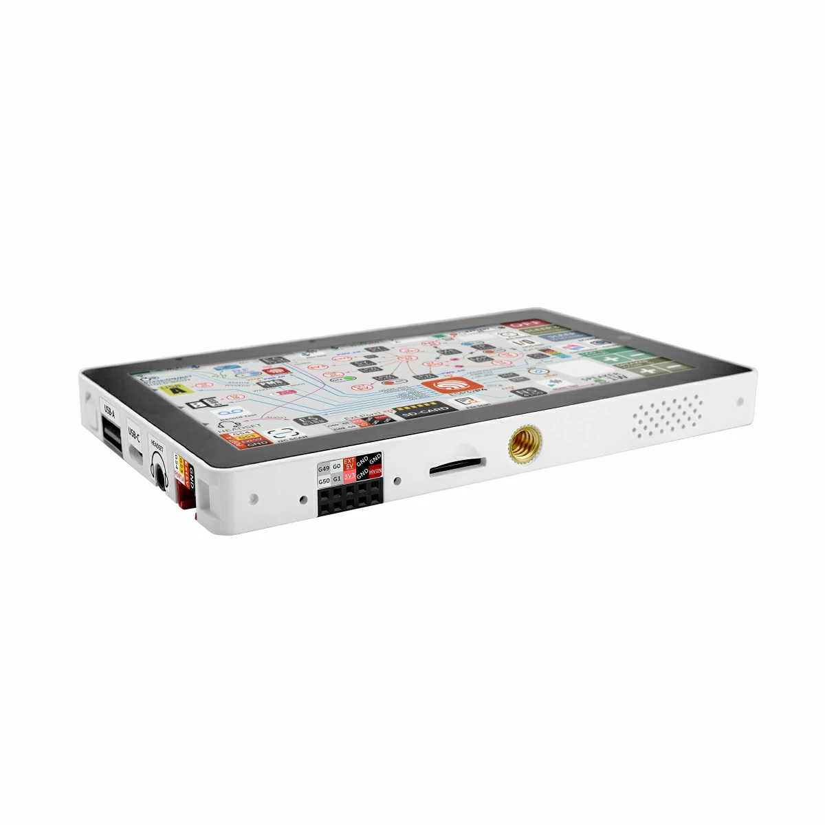
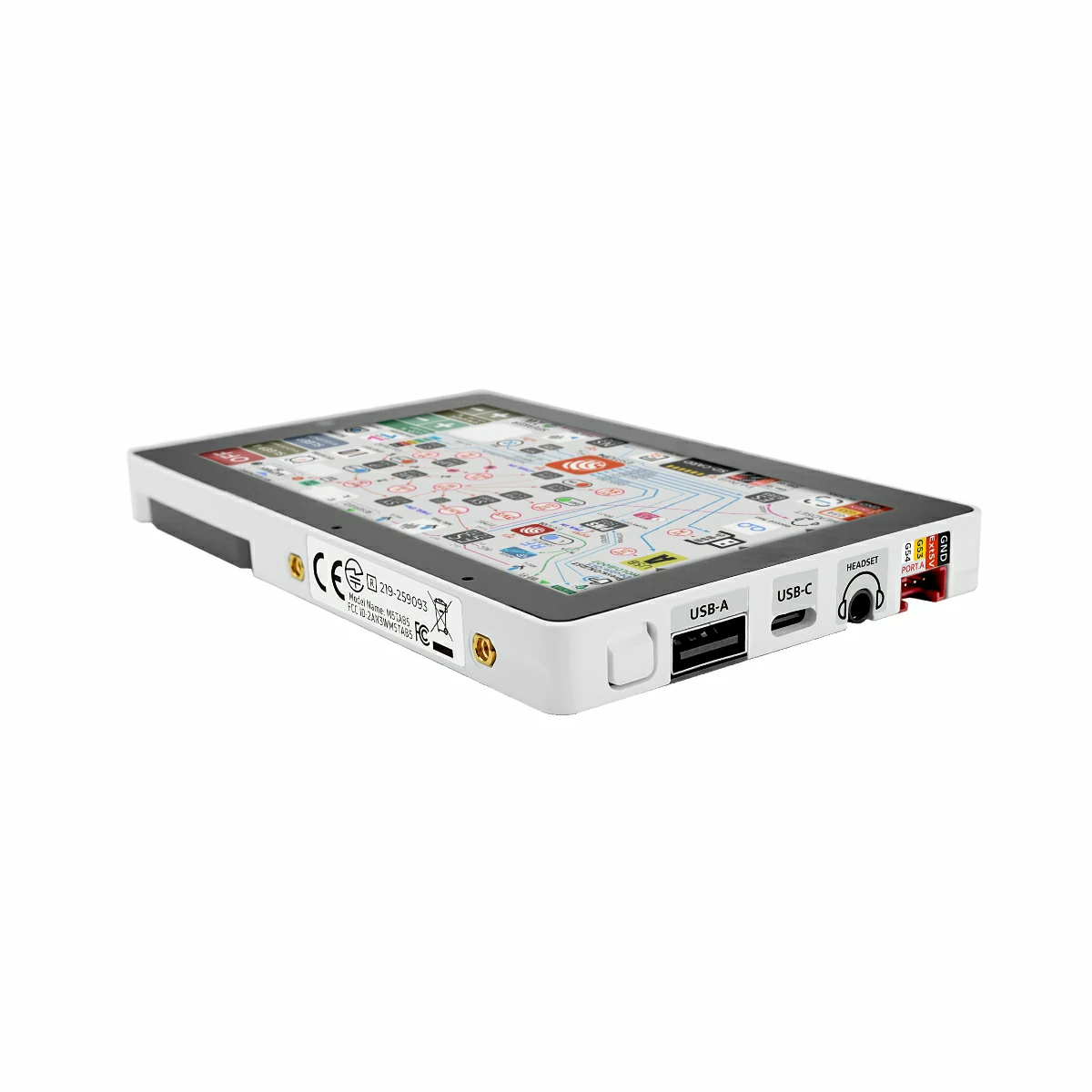
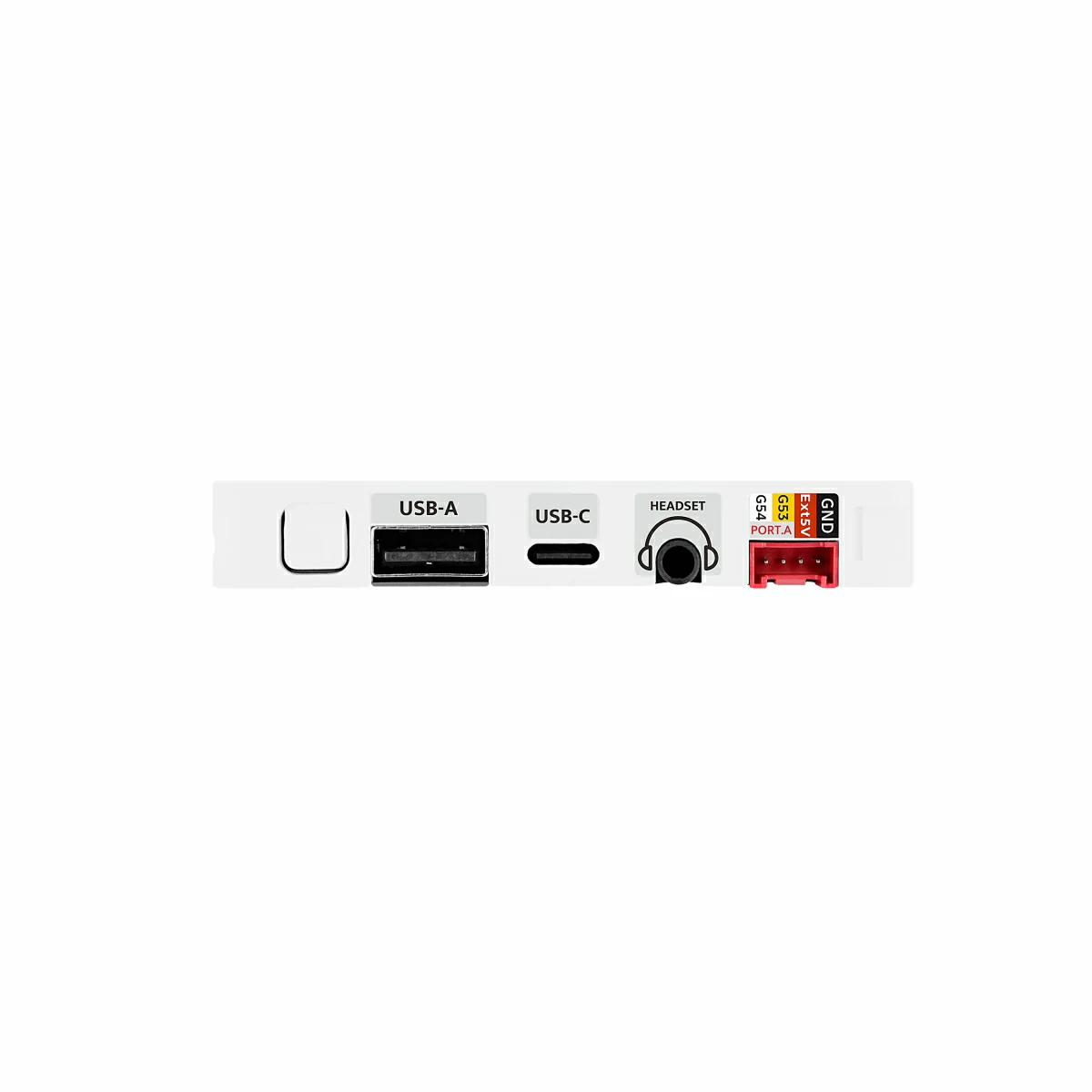
Peripheral interfaces include USB Type-A (Host) and USB Type-C (USB 2.0 OTG) for mouse, keyboard and other devices. Industrial users can leverage RS-485 (SIT3088 + switchable 120Ω terminator). HY2.0-4P, M5-Bus, GPIO_EXT headers, a microSD slot, and reserved STAMP pads (for Cat-M, NB-IoT, LoRaWAN, etc.) enable versatile sensor and communication expansion. Reset/Boot buttons provide quick reset and download-mode entry.
Audio features consist of an ES8388 codec plus an ES7210 AEC front-end, a dual-mic array, 3.5mm headphone jack and speaker, supporting Hi-Fi recording/playback and accurate voice recognition. A BMI270 6-axis sensor (accelerometer + gyroscope, interrupt wake-up) can wake the MCU in motion-tracking scenarios, boosting response efficiency in low-power mode.
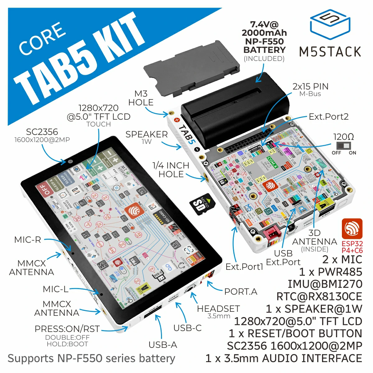
For time and power, Tab5 integrates an RX8130CE RTC (timed interrupt wake-up). The base accepts a removable NP-F550 battery and features MP4560 buck-boost, IP2326 charge management, and INA226 real-time monitoring for stable standalone operation.
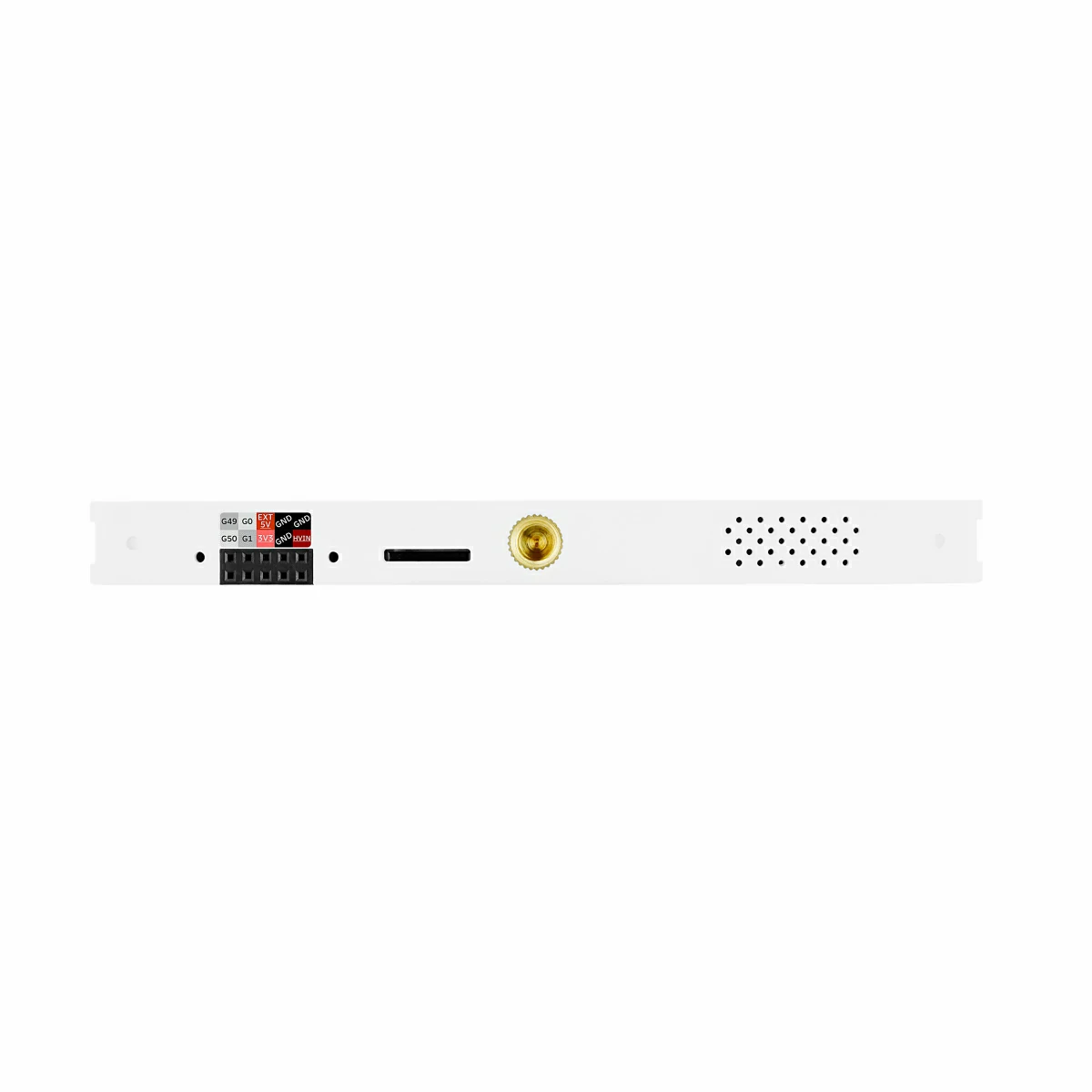
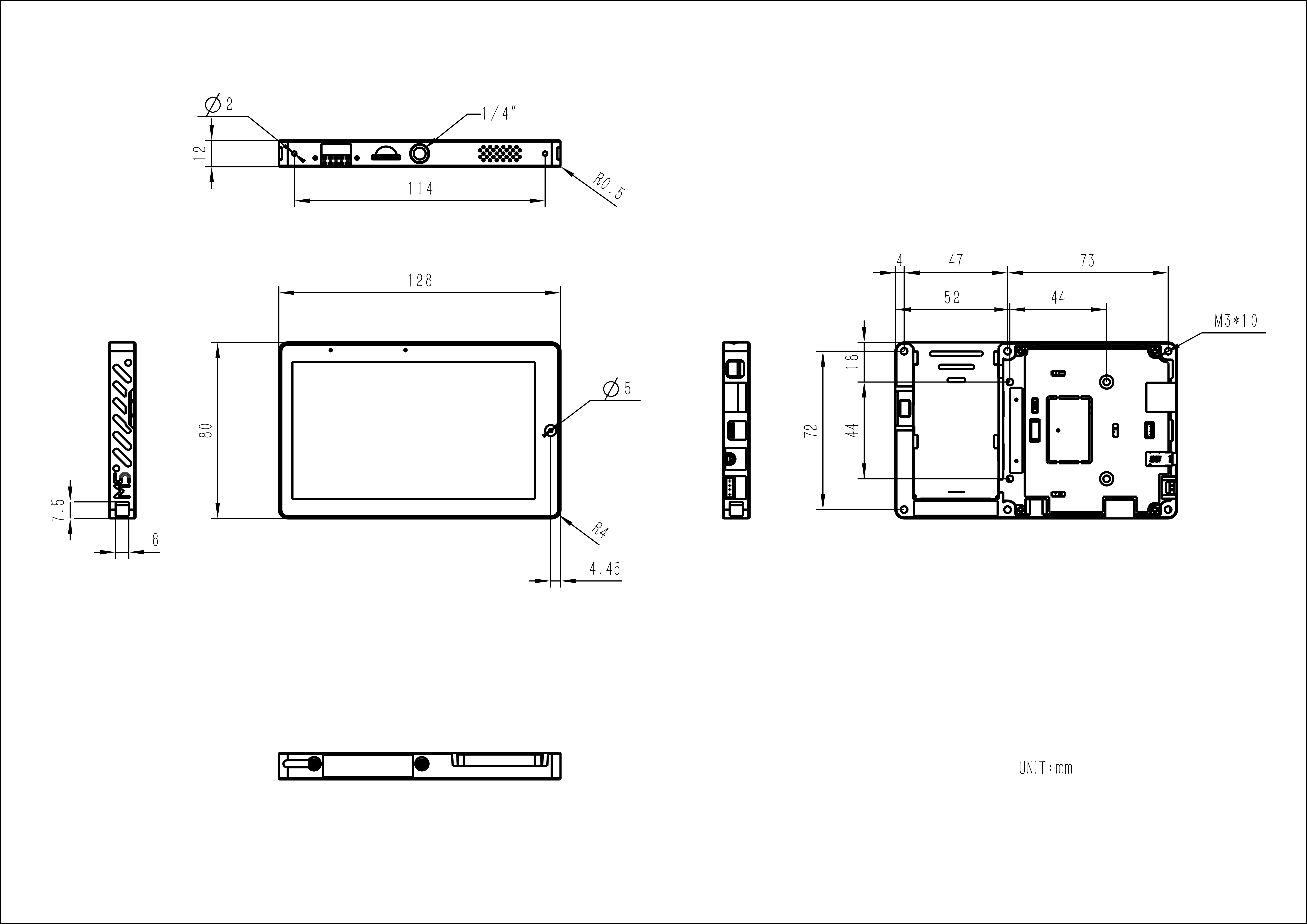
A 1/4″-20 tripod nut on the side allows direct mounting to a tripod or bracket.
Applications include smart-home control, remote monitoring, industrial automation, IoT prototyping and education, offering a full-featured, easily expandable high-performance platform.
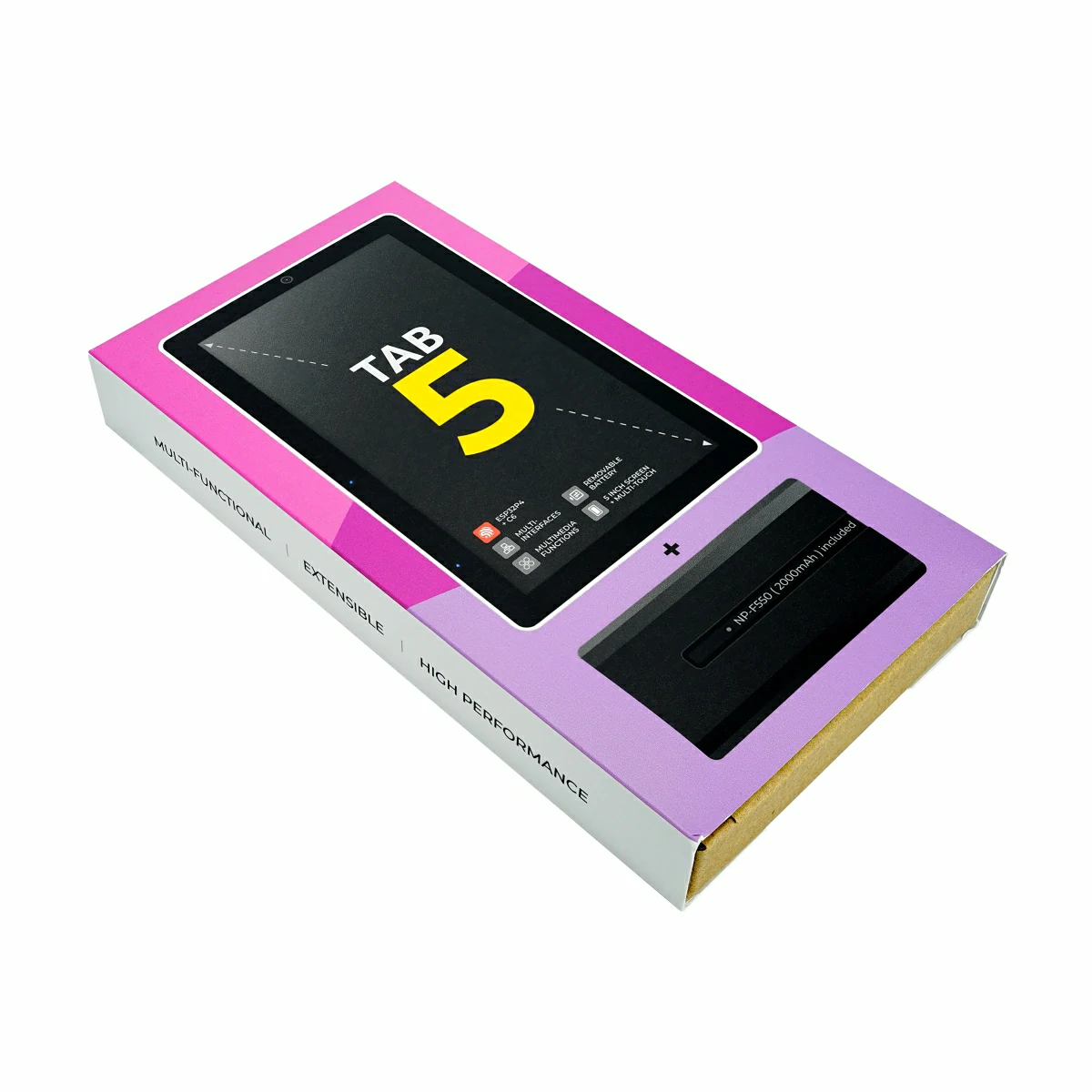
The Tab5 Kit is a complete set with a removable NP-F550 battery, whereas the standard Tab5 has no battery and requires an external power source or a separately purchased battery.
Under standard usage environment (screen brightness 50%, Wi‑Fi always on, background tasks running), Tab5 built-in battery discharges from full (8.23 V) to shutdown threshold (6.0 V), lasting about 6 hours.
Operating Temperature
0 ~ 40°C
Product Size
Tab5: 128.0 x 80.0 x 12.0mm Tab5 Kit: 128.0 x 80.0 x 26.7mm
Product Weight
Tab5: 118.4g Tab5 Kit: 217.3g Battery: 98.9g
Package Size
Tab5: 148.0 x 103.0 x 21.0mm Tab5 Kit: 191.0 x 103.0 x 25.0mm
Gross Weight
Tab5: 161.5g Tab5 Kit: 280.5g
Learn
Tab5 Power Supply
Tab5 Power Supply Notes
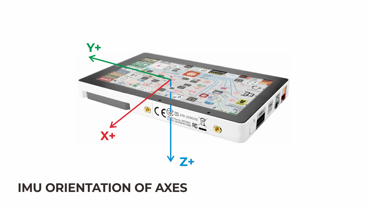
Before disconnecting the power or replacing the battery, please perform a shutdown first. If the power is disconnected directly, wait 5 seconds before powering on again; otherwise, the IMU sensor may fail to initialize properly due to abnormal voltage.
Tab5 Charging
Tab5 Charging Notes
Tab5 can only be charged after the device is powered on and initialized. Charging is not possible when the device is off.
Power On/Off
Power On/Off
When the device is powered by a USB data cable or battery, press the power button once to power on while it is off. While it is on, double-press the power button to shut it down.
Download Mode
Download Mode
With the USB data cable connected or the battery supplying power, press and hold the reset button (about 2 seconds) until the internal green LED starts flashing rapidly. Release the button and the device will enter download mode, waiting for firmware flashing.
Battery Installation Notes
Battery Installation
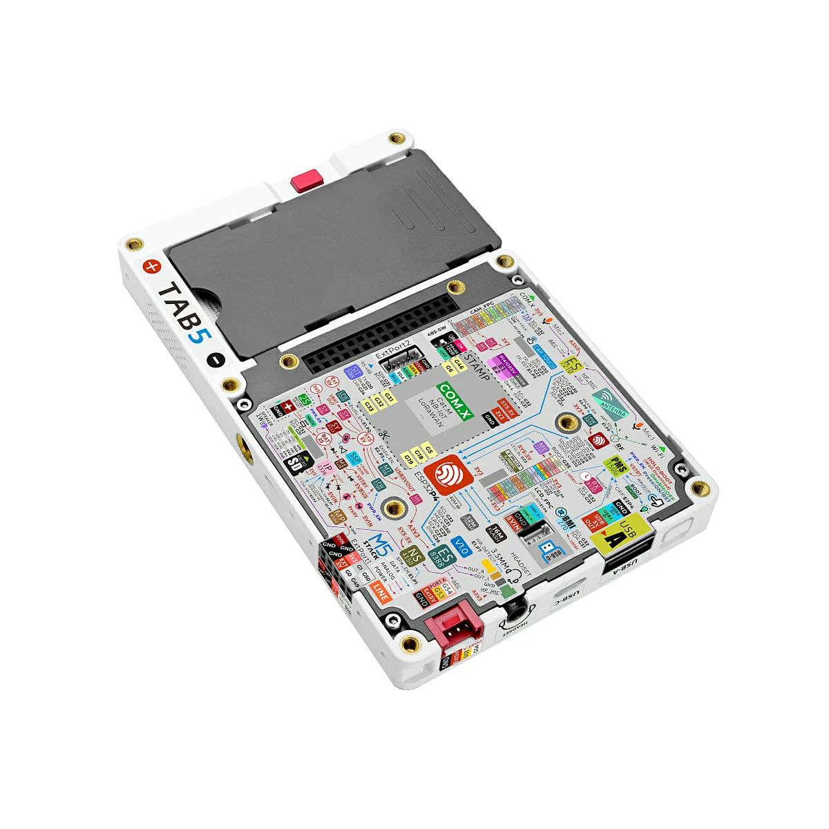
With the device powered off, press and hold the red locking button on the side of the main board. Align the metal spring contacts on the back of the battery module with the “BATTERY” slot on the main board, then slide it downward along the rail until the battery module fits flush with the main board. Release the red button to complete installation and start powering the device.
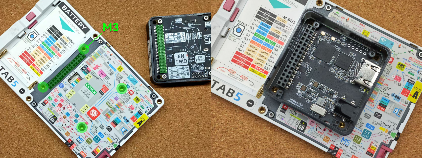
M5-Bus Expansion
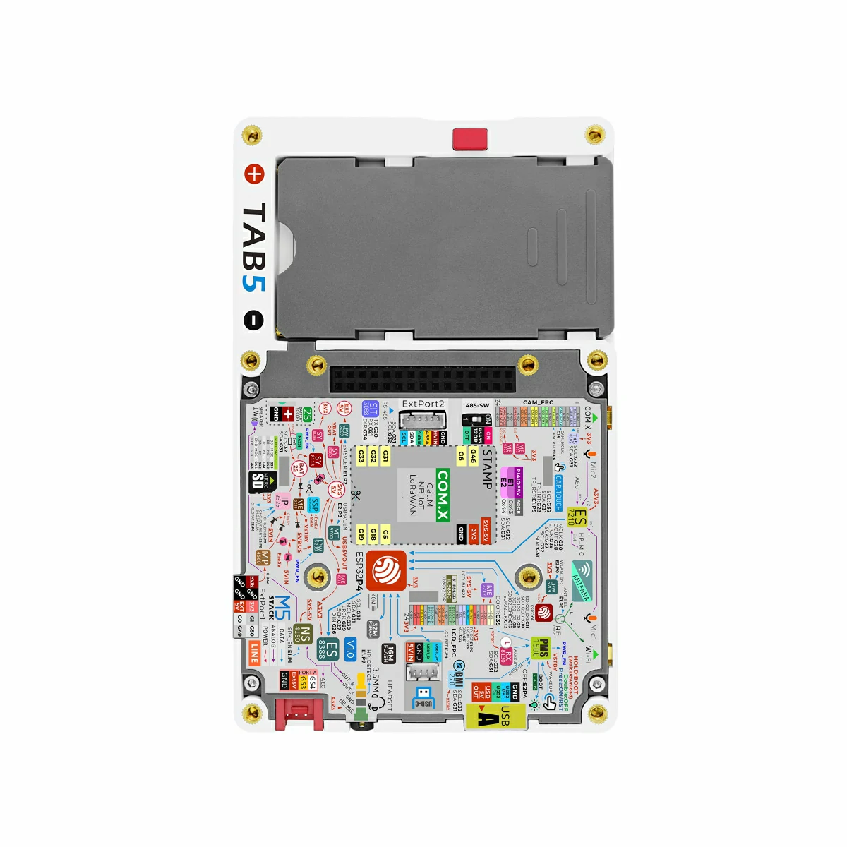
M5-Bus Expansion
As shown below, the back of the Tab5 integrates an M5-Bus connector, which can be used to expand Module series products.
RF_PTH_L_INT_H_EXT: Used to switch between the internal Wi-Fi antenna and the external SMA antenna. Low level selects the internal antenna, while high level selects the external antenna.
EXT_5V_BUS: Provides 5V power to the Tab5 rear M5-Bus, the side 2.54-10P expansion port, and the HY2.0-4P interface. The power output can be controlled via EXT5V_EN.
PI4IOE5V6408-2 (0x44)
E2.P0
E2.P3
E2.P4
E2.P5
E2.P6
E2.P7
ESP32-C6
WLAN_PWR_EN
USB-A
USB5V_EN
DEVICE PWR
PWROFF_PLUSE
IP2326 (CHARGE IC)
nCHG_QC_EN
CHG_STAT_LED
CHG_EN
WLAN_PWR_EN: Enables power supply for the internal ESP32-C6 (Wi-Fi SoC).
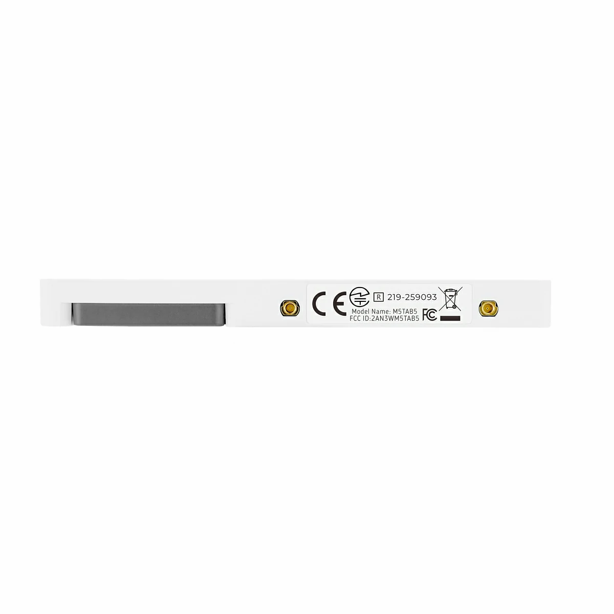
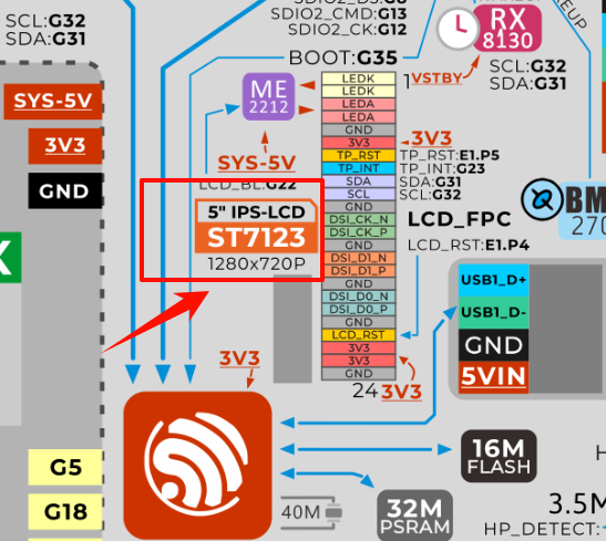
Starting from October 14, 2025, the Tab5’s original independent display driver ILI9881C and touch driver GT911 will be replaced by the integrated display‑touch driver ST7123. Some early firmware builds may not run properly. The latest versions of M5Unified and M5GFX have already been adapted for compatibility with this new screen driver, and older programs can be recompiled using the latest M5Unified and M5GFX to achieve proper compatibility. By checking the sticker on the back of the Tab5 product, you can confirm the driver model of the device.
Tab5 screen driver solution optimization: the original independent display driver ILI9881C and touch driver GT911 have been replaced with the integrated display‑touch driver ST7123.