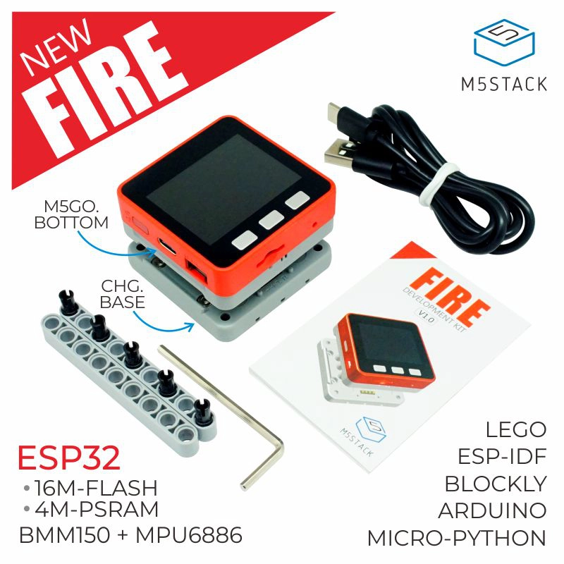
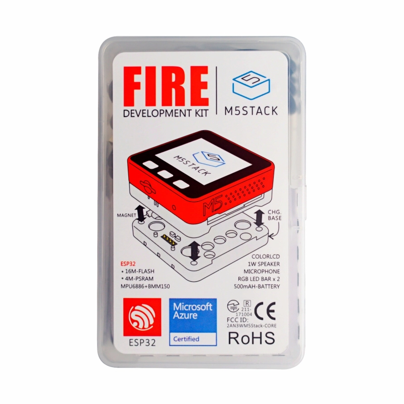
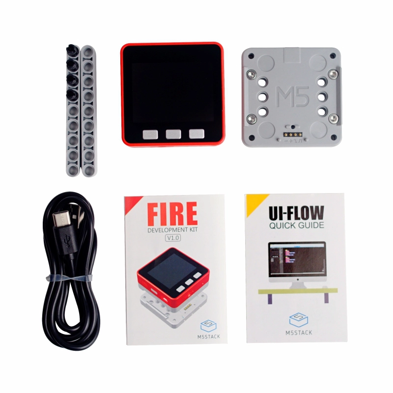
Fire is a high-performance development kit in the M5Stack series. As an upgraded version of the Gray kit, it features a nine-axis motion sensor (six-axis accelerometer + three-axis magnetometer) and enhanced hardware resources: 16MB Flash, 8MB PSRAM, an enhanced Base (M5GO base and M5GO charging base), and a larger capacity battery. For developers with demanding hardware performance requirements, Fire is an excellent choice.
The motion sensor can be used in various applications to detect acceleration, angle, trajectory extension, and other data. Based on these, related products such as motion data collectors and 3D remote gesture controllers can be developed.
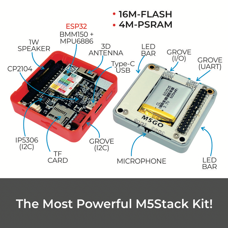
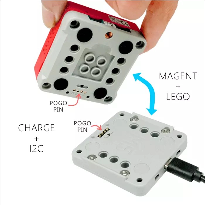
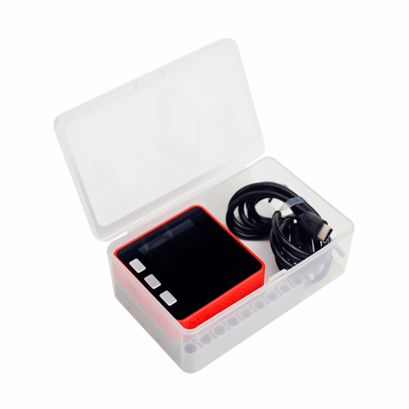
Fire consists of three detachable parts. The top part, like other M5 hosts, contains the circuit board, chips, LCD screen, 2.4G antenna, various electronic components, and interface components. The middle part is called the M5GO base, which provides a lithium battery, M5-Bus socket, LED strip, and three GROVE expansion ports. The bottom part is the charging base, which can be connected to the M5GO base via POGO pins for charging.
ESP32-D0WDQ6@Dual-core processor, Main frequency 240MHz
DMIPS
600
SRAM
520KB
Flash
16MB
PSRAM
8MB Quad
Wi-Fi
2.4 GHz Wi-Fi
Input Voltage
5V@500mA
Host Interface
USB Type-C x 1, GROVE (I2C+I/O+UART) x 1
IPS Screen
2 inch, 320x240 Colorful TFT LCD, ILI9342C, Max brightness 853nit
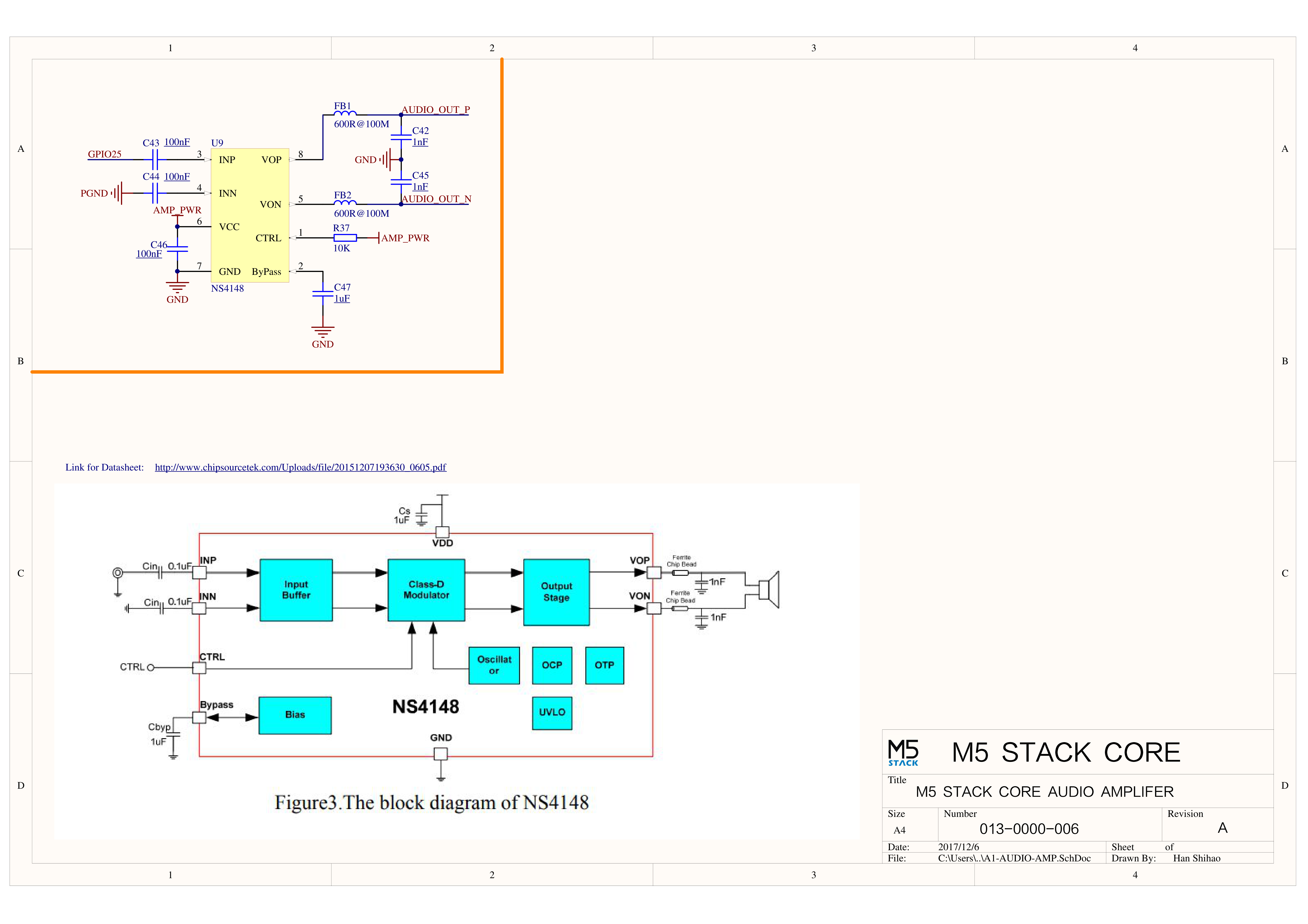
Speaker
1W-0928
Microphone
MEMS Analog BSE3729 Microphone
LED
SK6812 3535 RGB LED x 10
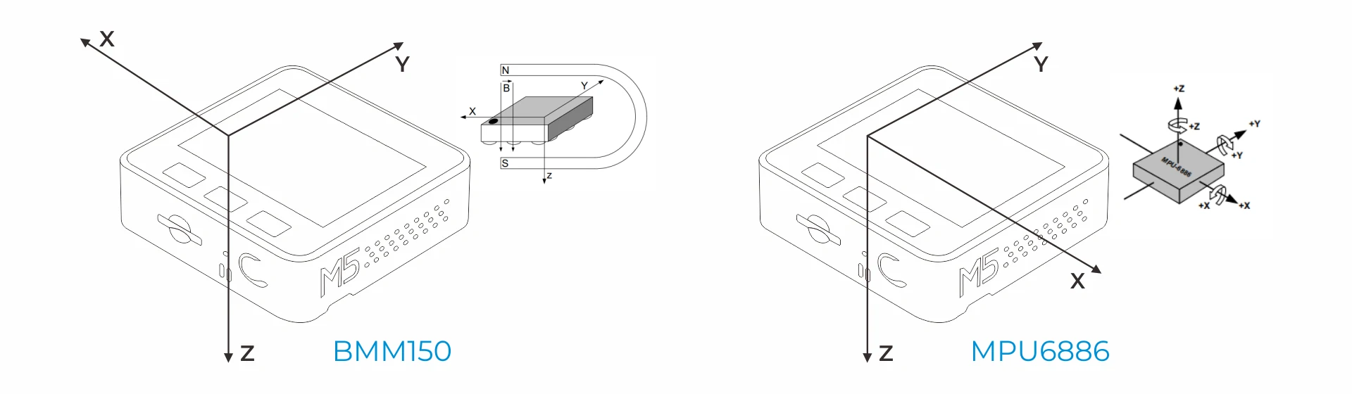
MEMS
BMM150 + SH200Q/MPU6886
Antenna
2.4G 3D antenna
Base Interface
PortA (I2C), PortB (GPIO), PortC (UART)
Battery
500mAh@3.7V, inside vb
Operating Temperature
0 ~ 60°C
Case Material
Plastic (PC)
Product Size
54.0 x 54.0 x 28.6mm
Product Weight
62.6g
Package Size
106.7 x 69.1 x 40.4mm
Gross Weight
123.8g
Learn
BMM150 Magnetic Field Interference
Products with magnets may interfere with the BMM150 magnetic field sensor, causing abnormal readings. When used with an M5 master control device containing a magnet, the magnet needs to be removed, and at the same time, the BMM150 sensor should be kept away from strong magnetic fields.
Power On/Off
Power On/Off Operations
Power On: Click the red power button on the left Power Off: Quickly double-click the red power button on the left USB Power Supply: By default, the device cannot be powered off when connected to USB.
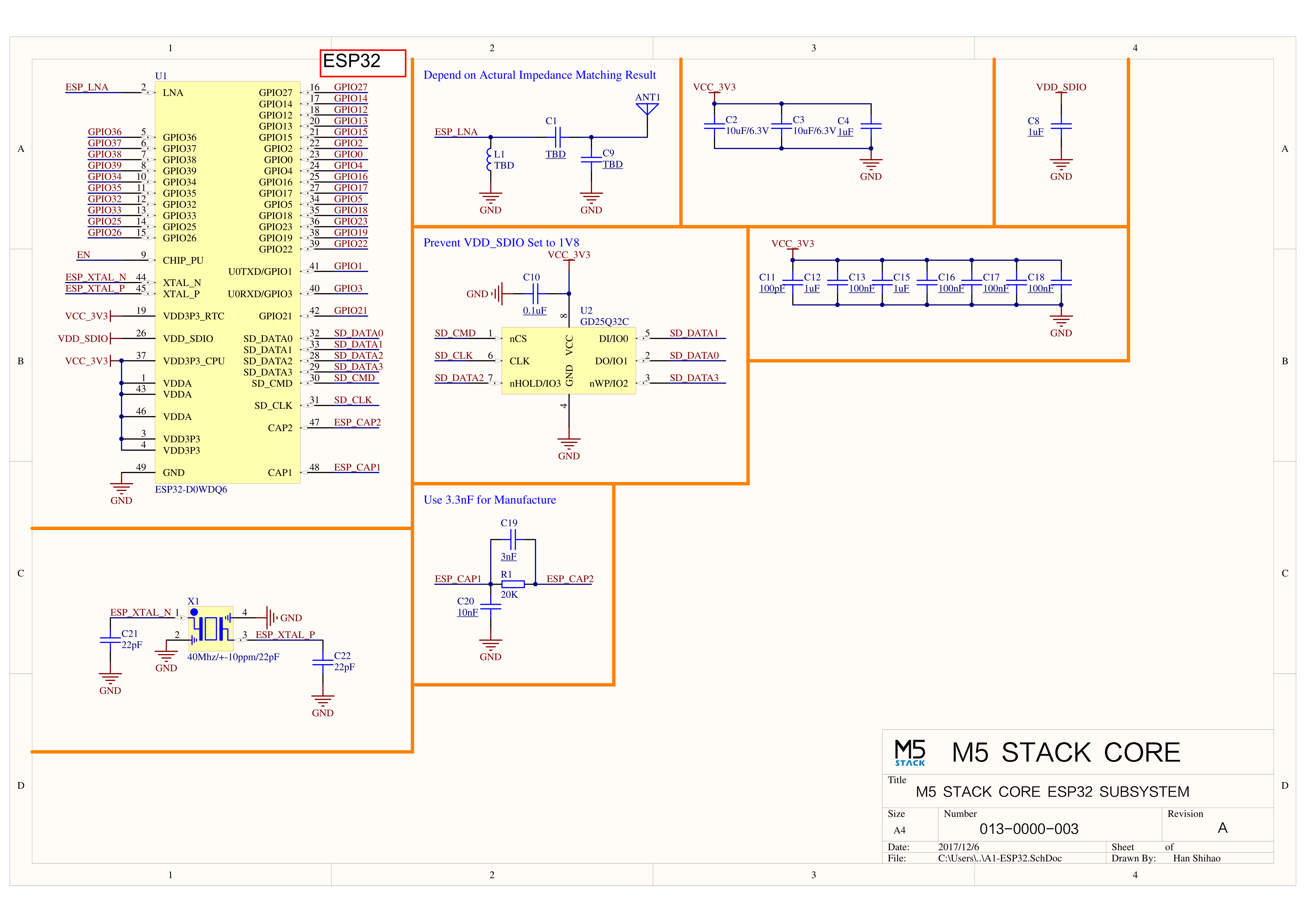
Note: GPIO 16 / 17 in FIRE are connected to PSRAM by default. Therefore, when connecting or stacking other functional modules, be careful to avoid conflicts with these two pins to prevent unstable operation.
LCD Resolution: 320x240
TF Card supports up to 16GB
ESP32-D0WDQ6
G23
G19
G18
G14
G27
G33
G32
G4
ILI9342C
MOSI/MISO
/
CLK
CS
DC
RST
BL
TF Card
MOSI
MISO
CLK
CS
Buttons & Speaker
ESP32-D0WDQ6
G39
G38
G37
G25
Button Pins
BUTTON A
BUTTON B
BUTTON C
Speaker
Speaker Pin
GROVE Interface A & IP5306
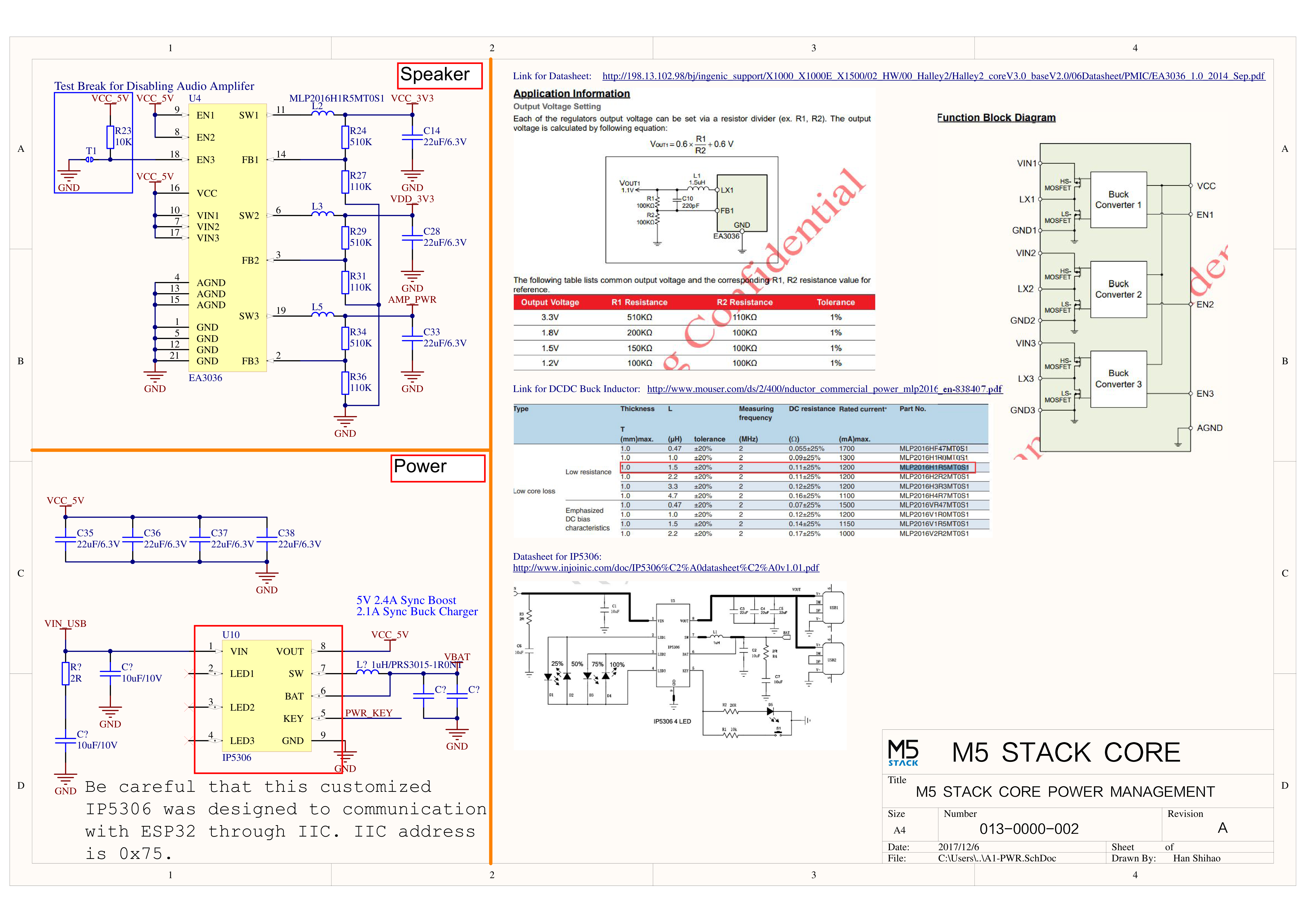
The power management chip (IP5306) is a custom I2C version with an I2C address of 0x75. Click here to view the IP5306 register manual.
ESP32-D0WDQ6
G22
G21
5V
GND
GROVE A
SCL
SDA
5V
GND
IP5306 (0x75)
SCL
SDA
5V
GND
IP5306 Charge/Discharge Voltage Parameters
Charge
Discharge
0.00 ~ 3.40V -> 0%
4.20 ~ 4.07V -> 100%
3.40 ~ 3.61V -> 25%
4.07 ~ 3.81V -> 75%
3.61 ~ 3.88V -> 50%
3.81 ~ 3.55V -> 50%
3.88 ~ 4.12V -> 75%
3.55 ~ 3.33V -> 25%
4.12 ~ / -> 100%
3.33 ~ 0.00V -> 0%
MPU6886 3-Axis Accelerometer + 3-Axis Gyroscope
MPU6886 I2C address 0x68
ESP32-D0WDQ6
G22
G21
5V
GND
MPU6886 (0x68)
SCL
SDA
5V
GND
BMM150 3-Axis Magnetometer
BMM150 I2C address 0x10
ESP32-D0WDQ6
G22
G21
5V
GND
BMM150 (0x10)
SCL
SDA
5V
GND
M5GO Base PinMap
LED Strip & Microphone & Speaker
ESP32-D0WDQ6
G15
G34
G25
Hardware
SIG Pin
MIC Pin
Speaker Pin
ESP32 ADC/DAC
ADC1
ADC2
DAC1
DAC2
8 Channels
10 Channels
2 Channels
2 Channels
G32-39
G0/2/4/12-15/25-27
G25
G26
HY2.0-4P
HY2.0-4P
Black
Red
Yellow
White
PORT.A
GND
5V
G21
G22
PORT.B
GND
5V
G26
G36
PORT.C
GND
5V
G16
G17
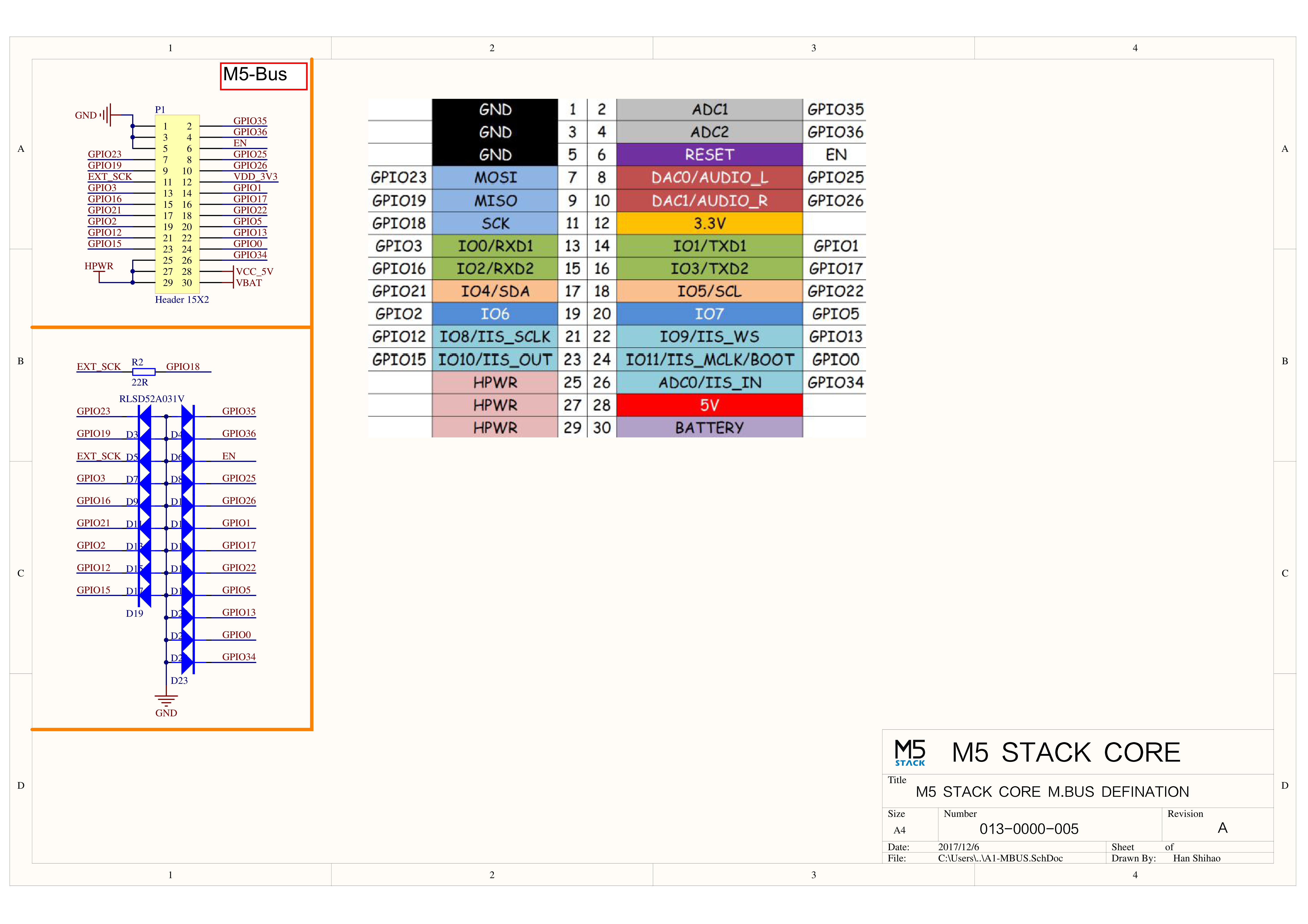
M5-Bus
FUNC
PIN
LEFT
RIGHT
PIN
FUNC
GND
1
2
G35
ADC
GND
3
4
G36
ADC
GND
5
6
RST
EN
MOSI
G23
7
8
G25
DAC/SPK
MISO
G19
9
10
G26
DAC
SCK
G18
11
12
3V3
RXD0
G3
13
14
G1
TXD0
RXD2
G16
15
16
G17
TXD2
Int SDA
G21
17
18
G22
Int SCL
GPIO
G2
19
20
G5
GPIO
I2S_SK
G12
21
22
G13
I2S_WS
I2S_OUT
G15
23
24
G0
I2S_MK
HPWR
25
26
G34
I2S_IN
HPWR
27
28
5V
HPWR
29
30
BAT
When using GPIO15 for RGB LED, it is recommended to initialize the pin with pinMode(15, OUTPUT_OPEN_DRAIN);
For more information on pin allocation and pin remapping, refer to the ESP32 datasheet
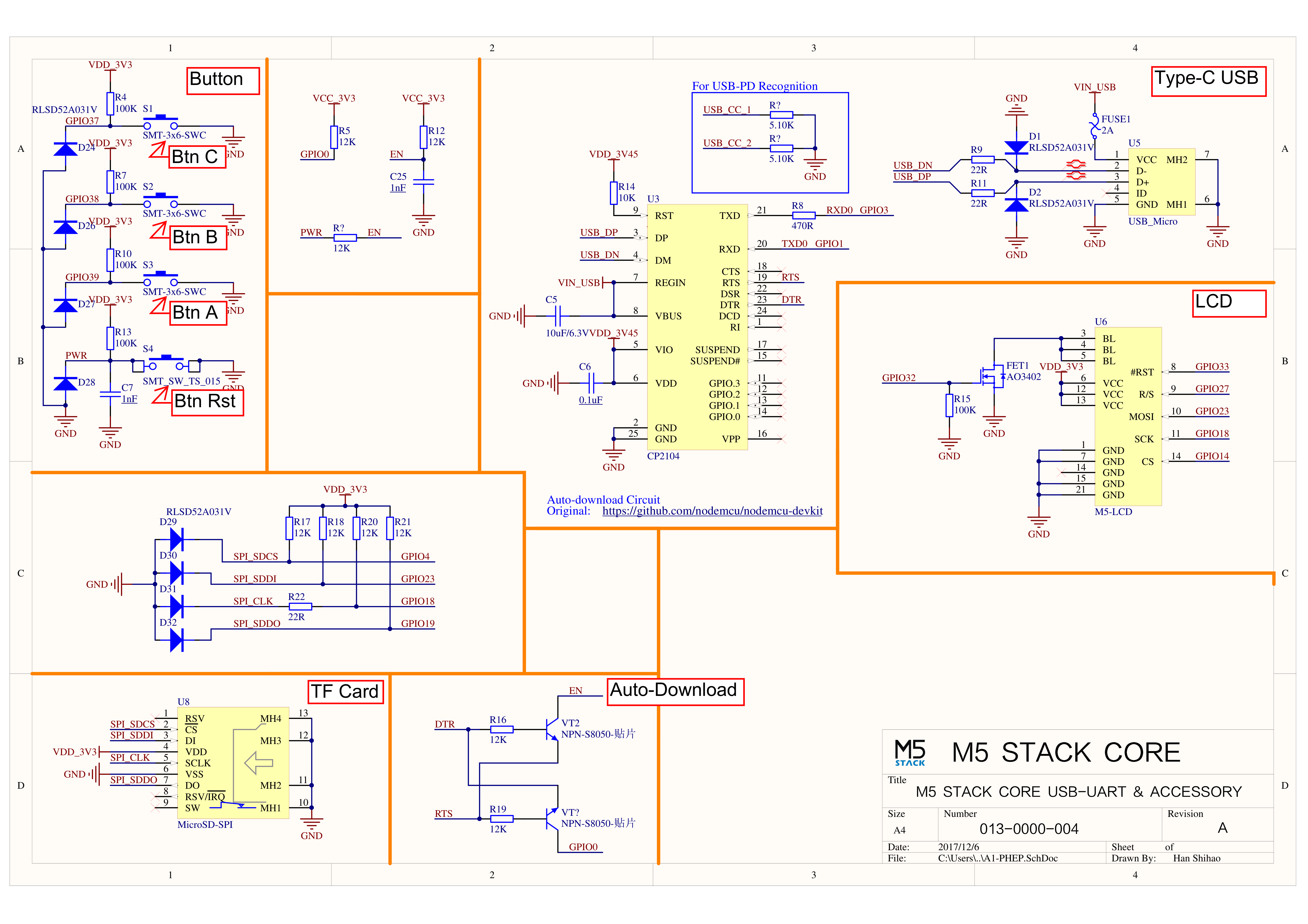
Click the links below to download the drivers for your operating system. There are currently two versions of driver chips: CP210X (for CP2104 version) and CP34X (for CH9102 version). After extracting the compressed package, select the installation package corresponding to your operating system's bit version. (If you are unsure which USB chip your device uses, you can install both drivers. CH9102_VCP_SER_MacOS v1.7 may report an error during installation, but it is actually installed successfully, so you can ignore it.) If you encounter issues with downloading programs (such as timeouts or "Failed to write to target RAM"), try reinstalling the device drivers.
To compare information on the controller series products, you can visit the Product Selection Table, check the target products, and get the comparison results. The selection table covers key information such as core parameters and functional features, and supports comparison of multiple products simultaneously.
Version Change
Release Date
Product Change
Note:
2018.6
Initial public release
/
2019.7
MPU9250 changed to SH200Q+BMM150, TN screen changed to IPS screen
before use . pls upgrade your M5Stack lib to the latest version (after 0.2.8) to solve screen reverse color problem.
2019.8
SH200Q changed to MPU6886
/
2019.11
Battery capacity changed from 600mAh to 500mAh
/
2020.4
PSRAM Size changed from 4MB to 8MB
/
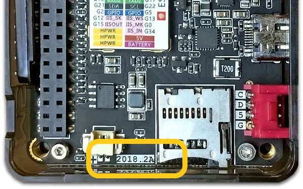
Note: 2018.2A PCB version of the device does not support C2C (Type-C to Type-C) connection and PD power supply.